
Basler ElectricDECS-200-1C Digital Excitation Control System
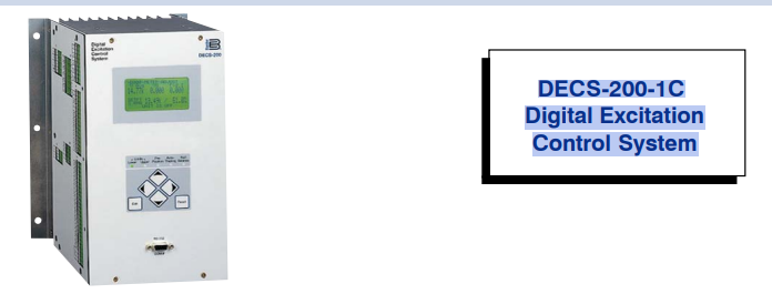
One DECS-200 Digital Excitation Control System can accommodate 32Vdc, 63Vdc, or 125Vdc applications up to 15Adc. This unique flexibility provides precision control of generators of virtually any size. The DECS-200 also incorporates a pulse width modulated power stage, which improves system performances in non-linear load applications.
FEATURES
• Microprocessor-based design
• True RMS sensing, single or three phase
• 32Vdc, 63Vdc, and 125Vdc outputs at 15Adc
• 0.25% Voltage Regulation Accuracy
• Setup from front panel HMI or by PC with Windows® setup software included
• 20 standard stability selections
• User customizable stability selection
• Paralleling compensation
• Underfrequency compensation or V/Hz Ratio Limiter
• Soft start buildup
• Field Current Regulation Mode (Manual Mode)
• Autotracking between operating modes and between DECS-200 units
(optional)
• Minimum Excitation Limiter (Internally generated or customizable)
• On and off-line Maximum Excitation Limiters
• Stator Current Limiter
• Var and Power Factor Controllers
• Exciter Diode Monitoring (EDM)
• Sequence of Events Recording
• Oscillography
FEATURES, continued
• Voltage Matching
• Eight (8) generator protection features
• Programmable output contacts
• Front panel backlit LCD display
• Front panel mounted RS-232 and side RS-485
communications ports
• Modbus™ protocol for RS-485 input allows
communications up to 4000 feet away
• <1% metering accuracy for 12 generator parameters
• Remote set point control via:
- Contact inputs
- Proportional control via ±10Vdc or 4-20mA
- Communications inputs RS-232 (ASCII) or RS-485
(Modbus™)
• Meets C37.90.1-1989 for Surge Withstand and Fast
Transient
• UL recognized, CSA certified, CE compliant, DNV
certified, GOST-R certified, Byelorussian certified
• U.S. Patent Number 5,294,879
DESCRIPTION
The microprocessor based DECS-200 is a total excitation control system in one enclosure. It contains all the
functionality necessary to limit, control, and protect a
generator from operating outside of the machine's
capability. A feature of DECS-200's sophisticated
design allows the nonactive control mode within the
unit to follow the active mode, permitting bumpless
transfer between modes. The optional external tracking
feature also allows for unit-to-unit communication,
permitting autofollowing and transfer between DECS200 units. It can also communicate to a PC via the front
panel RS-232 port for local programming and metering,
and it can communicate via Modbus™ protocol via the
side RS-485 port for communications up to 4000 feet
away from the DECS-200 unit. The DECS-200 has all
the features, functionality, flexibility and programmability expected from a state-of-the-art microprocessor
based product.
APPLICATIONS
The DECS-200 is an excitation control system used to control the output voltage, vars or power factor of a
synchronous generator by varying or controlling the amount of dc excitation applied to the generator's exciter
field. The DECS-200 is suitable for virtually any size machine
SPECIFICATIONS, continued
Generator Current Sensing Two ac current sensing ranges and two channel (phase) inputs:
• For metering and control: 1A and 5A.
• For cross current compensation: 1A and 5A.
Sensing Burden Voltage: Less than 1VA per phase.
Current: Less than 1VA.
Parallel Compensation: Less than 1VA.
Contact Switching Inputs 11 contact switching inputs are supplied with 24Vdc to accommodate dry
contacts. Contacts are as follows:
• Start • Var/PF Enable
• Stop • Pre-position
• Secondary DECS Enabled (optional) • Raise Switch
• Unit/Parallel Operation • Lower Switch
• AVR Mode • Alarm Rest
• FCR Mode
Remote Set Point Control Two separate analog inputs for remote set point control. Typically used to accept
(Accessory Input) a signal from a Power System Stabilizer. Select one from the configuration menu.
• ±10Vdc
• 4 to 20 milliamperes
COMMUNICATION There are three communication ports, two RS-232 and one RS-485: COM0: RS-232, 9 pin, sub-D connector located on front panel and used to communicate with local computers. 1200 to 19200 baud, 8N1 full duplex, ASCII commands COM1: RS-232, 9 pin, sub-D connector located on right side panel and used to connect primary and backup DECS-200 units. Port is only used for optional autotracking. COM2: RS-485, located on left side panel and used to communicate with local or remote computers or other devices. 1200 to 19200 baud, 8N1 half duplex, Modbus™ protocol
SPECIFICATIONS, continued
REGULATION ACCURACY
AVR Mode: Voltage regulation equals ±0.25% over the load range at rated power factor and constant
generator frequency. Steady state stability equals ±0.1% at a constant load and generator frequency.
Temperature drift equals ±0.5% for 0 to 50°C temperature change. Underfrequency (volts/hertz)
characteristic slope from 0 to 3.0 P.U. is adjustable in 0.1 P.U. increments.
FCR Mode: Field current regulation equals ±1.0% of the nominal value for 10% of the bridge input voltage
change or 20% of the field resistance change.
var Mode: ±2.0% of the nominal VA rating at the rated frequency.
PF Mode: ±0.02 PF in the set point PF for the real power between 10 and 100% at the rated frequency.
(e.g. -set point PF=0.80, PF regulation is from 0.78 to 0.82 PF.)
Internal autotracking(optional): ±0.5% of the nominal field voltage change when transferring.
PARALLEL COMPENSATION Can use either reactive droop or reactive differential (cross-current) compensation. Adjustable from 0 to 30% of the rated generator voltage droop with optional 1 ampere or less or 5 amperes
or less input. Line drop compensation uses this same parameter; however, it is adjustable from -30% to 0.
FIELD OVERVOLTAGE PROTECTION Adjustable in increments of 1.0Vdc from 1.0 to 325Vdc rated output
voltage with a 0.2 to a 0.2 to 30 second inverse time delay settable in increments of 0.1 second.
FIELD OVERCURRENT PROTECTION Adjustable in increments of 0.1Adc steps of rated field current from 0 to
16Adc excitation current setting with an inverse time delay (ANSI C50.13).
EXCITER DIODE MONITOR (EDM) The DECS-200's EDM can detect open and shorted diodes on brushless
generators. To do this, the DECS-200 requires the user to input the number of generator poles and the number of
exciter poles (both adjustable from 0 to 20 in increments of 2). The open and shorted diode ripple threshold is
adjustable from 0 to 100% of field current. The open diode protection time delay is adjustable from 10 to 60
seconds, and the shorted diode protection time delay is adjustable from 5 to 30 seconds.
GENERATOR UNDERVOLTAGE PROTECTION Adjustable in increments of 1Vac from 0 to 30kV sensing voltage
setting with a 0.5 to 60 second time delay (ANSI C50.13) settable in increments of 0.1 sec.
GENERATOR OVERVOLTAGE PROTECTION Adjustable in increments of 1Vac from 0 to 30kV sensing voltage
with a 0.1 to 60 second time delay (ANSI C50.13) settable in increments of 0.1 second.
GENERATOR LOSS OF FIELD PROTECTION Adjustable in increments of 1 kVar from 0 to 3,000Mvar, with a
0.1 to 9.9 second delay settable in increments of 0.1 second.
LOSS OF SENSING The loss of sensing setting for both balanced and unbalanced generator voltage is adjustable from 0 to 100% of nominal generator voltage. The protection delay is adjustable from 0 to 30 seconds in 0.1
increments.
SOFT START Functional in AVR and FCR with an adjustable rate of 1 to 7200 seconds in one second increments.
SUMMING POINT and TAKEOVER TYPE
OVEREXCITATION LIMITING Limiter response time is less than three cycles.
SUMMING POINT TYPE:
On-Line High Current Level (instantaneous) set point adjustable from 0 to 30.0Adc in 0.1Adc increments. Limiting occurs for a time period ranging from 0 to 10 sec., settable in 1 sec. increments.
Medium Current Level set point adjustable from 0 to 20Adc in 0.1Adc increments.
Limiting occurs for a time period ranging from 0 to 120 seconds, settable in 1 sec. increments.
Low Current Level set point adjustable from 0 to 15Adc in 0.1Adc increments. Limiting occurs
SPECIFICATIONS, continued
Off-Line High Current Level (instantaneous) set point adjustable from 0 to 30Adc in 0.1Adc increments.
Limiting occurs for a time period ranging from 0 to 10 seconds, settable in 1 second increments.
Low Current Level set point adjustable from 0 to 15Adc in 0.1Adc increments. Limiting occurs indefinitely.
TAKEOVER TYPE OEL: The Takeover OEL uses an I2
t characteristic.
On-Line High Level: High Current Level (instantaneous) set point is adjustable from 0 to 30.0Adc in 0.1
Adc increments.
Low Level: Low Current set point is adjustable from 0 to 15.0Adc in 0.1Adc increments. Limint
occurs indefinitely.
Time Dial - This setting determines the inverse time curve selected.
Off-Line High Level - High current level (instantaneous) set point is adjustable from 0 to 30.0Adc in
0.1Adc increments.
Low Level - Low current set point is adjustable from 0 to 15.0Adc in 0.1Adc increments. Limiting
occurs indefinitely.
Time Dial - This setting determines the inverse time curve selected.
UNDEREXCITATION LIMITING Adjustments based on generator ratings.
STATOR CURRENT LIMITING
High Level - High current level set point adjustable from 0 to 60,000Aac in 0.1Aac increments.
Limiting occurs for a time period ranging from 0 to 60 seconds, settable in 0.1 sec. increments.
Low Level - Low current level set point adjustable from 0 to 60,000Aac in 0.1Aac increments.
Limiting occurs indefinitely.
SEQUENCE OF EVENT RECORDING (SER) 127 event reports stored in volatile memory (retrievable via
BESTCOMS). SER triggered by: Input/Output status changes, system operating status changes, and alarm annunciations.
OSCILLOGRAPHY Stores 8 records. Up to 6 variables can be logged in a record. Sampling rate: 600 data points
per log, pre-trigger adjustable from 0 to 599 data points, 4ms to 10sec intervals between data points (2.4sec to
6000sec. total log duration)
MANUAL EXCITATION CONTROL Regulates field current from 0 to 15.0A in increments of 0.1Adc.
VOLTAGE MATCHING Matches utility bus RMS voltage with generator output RMS voltage within ±0.15% of
the generator voltage
REAL TIME CLOCK Time displayed in either 12 hour or 24 hour format and can be selected to allow for daylight
savings timer. The date is selectable for two formats: d-m-y or m/d/y. Requires control power to operate. If power is
lost, the clock will need to be reset.
SURGE WITHSTAND CAPABILITY (SWC) IEEE C37.90.1-1989
FAST TRANSIENT IEEE C37.90.1-1989
HIGH POT. IEEE 421.3
ENVIRONMENTAL
Operating temperature: -40°C to +60°C (-40°F to +140°F) Storage temperature: -40°C to +85°C (-40°F to +185°F)
Salt Fog Per MIL-STD-810E, Method 509.3 (100 hrs. of salt fog, 100 hours of drying time)
Shock 15 Gs in each of three mutually perpendicular planes
Vibration 5-26Hz: 1.2Gs; 27-52Hz: 0.914mm (.036 inch) double amplitude; 53-500Hz: 5.0Gs
Size 8.08" (205mm) wide x 6.76" (171mm) deep x 12.0" (304mm) high
Weight 14 lbs. (6.35kg)
AGENCY UL recognized per Std. 508; UL file number E97035; CSA certified per Std. CAN/CSA-C22.2,
Number 14, CSA file number LR23131; CE compliant, EMC and LVD; Certified per DNV
FEATURES/FUNCTIONS
Voltage Regulation
The DECS-200 regulates the generator RMS voltage to within
0.25% from no-load to full-load. It does this by utilizing digital
signal processing and precise regulation algorithms developed
by Basler Electric, utilizing the experience gained in many years
of manufacturing tens of thousands of digital voltage regulators.
Stability
The DECS-200 utilizes proportional (P), integral (I) and derivative
(D) stability control. DECS-200 has 20 preprogrammed stability
(PID) settings for exciter field applications. This means that a
standard stability setting is already available for most applications/machines. The DECS-200 has a stability range that allows
for customizing the stability settings to fine tune the stability to
provide optimum customized generator transient performance.
Setup software contains PID selection program to assist in
determining the correct PID settings. The DECS-200 provides for
customizing the stability and transient performance of the Min/
Max Excitation Limiter and var/PF controllers by providing
additional stability adjustments.
Underfrequency Limiter or V/Hz Ratio Limiter
DECS-200 is selectable for either Underfrequency Limiter or a
V/Hz Ratio Limiter function. The underfrequency limiter slope can
be tuned to have 0 to 3 times p.u. Volts/Hz, in 0.1Hz increments,
and the corner frequency roll-off point can be set across a range
of 45 to 65Hz, in 0.1Hz increments. This adjustability allows the
DECS-200 to precisely match the operating characteristics of the
prime mover and the loads being applied to the generator. The
Volts/Hz Ratio Limiter clamps the regulation set point to prevent
operation above a V/Hz level that is prescribed by the slope of the
DECS-200. This feature is also useful for other potentially
damaging system conditions such as a change in system voltage
and re-duced frequency situations that exceed the V/Hz ratio.
Soft Start Voltage Buildup
Generator voltage overshoot can be harmful to the generator's
insulation system if not controlled. DECS-200 has a soft start
feature with a user-adjustable setting to govern the rate at which
the generator voltage is allowed to build up. This reduces the
amount of generator voltage overshoot form nominal operating
voltage during start-up of the generator system.
Paralleling Compensation
DECS-200 has provisions to parallel two or more generators
using reactive droop or reactive differential compensation with
the addition of an external current transformer with secondary
currents of 1 or 5Aac. The current input is rated at less than 1VA.
This low burden means that existing metering CTs can be used
and dedicated CTs are not required.
Set Point Control
DECS-200 has means for external set point adjustment of the
controlling mode of operation. This eliminates the need for
additional equipment like motor operated potentiometers for
remote control or multiple point control for the excitation system.
The operating mode's set point may be directly controlled by
raise/lower contact inputs or auxiliary inputs of 4-20mA or
±10Vdc. The auxiliary input adjusts the operating mode across its
predetermined adjustment range. The auxiliary input can be
provided from other controlling devices such as a power
system stabilizer. These devices modify the operation of the
DECS-200 to meet specific operating characteristics and requirements for the machine under DECS-200 control. Two more
methods of set point control may be achieved via the RS-232
communication port by using the Windows® based PC software
or by the RS-485 port using Modbus™ protocol. Regardless of
which method of set point is used (contact inputs, auxiliary input
or communications with a PC or PLC), traverse rates of all modes
of operation are independently adjustable. This means an
operator can customize the rate of adjustment and "feel" to meet
his/her needs.
Pre-position Inputs
DECS-200 provides the added flexibility of allowing a predetermined operating point for each mode of operation. With a contact
input to the DECS-200, the operating mode is driven to an
operating or regulation level assigned to that operation mode by
the operator or user. The pre-position inputs operate in one of two
modes, Maintain or Release. The Maintain mode prevents
adjustment of the setpoint as long as the pre-position contact is
closed. The release mode allows adjustment of the setpoint even
though the pre-position is closed. This feature allows the DECS200 to be configured for specific system and application needs.
Field Current Regulation Operating Mode
DECS-200 provides a manual channel of operation called Field
Current Regulation, or FCR, Mode. In this mode, DECS-200
regulates the field current generated by the internal PWM power
stage. It does not rely on the sensing input to DECS-200 and is,
therefore, a good source of backup excitation control when loss
of sensing is detected. In this mode, control of the generator is
totally dependent upon the operator to maintain nominal generator voltage as the load varies on the generator.
Var/Power Factor Controller Operating Mode
DECS-200 has, as another standard feature, two modes of
operation when the generator is in parallel with the utility power
grid. The DECS-200 has both var and PF modes of operation.
When the generator is in parallel with the utility grid, the DECS200 can regulate the var output of the generator to a specific var
level magnitude or it can vary the var output of the generator to
maintain a specific power factor as the kW load varies on the
generator.
Maximum Excitation Limiters
Overexcitation limiting (OEL) operates in all modes except FCR
mode. OEL senses the field current output of the voltage regulator or static exciter and limits the field current to prevent field
overheating. In FCR mode, the DECS-200 only announces that all
conditions for OEL are fulfilled and does not provide limiting. The
DECS-200 provides two types of overexcitation: Summing Point
and Takeover.
Summing Point Type OEL
Three OEL current levels are defined for on-line operation. They
are high, medium, and low. The generator can operate continuously at the low OEL current level and for programmed times at
the high and medium OEL current levels. Two OEL current levels
are defined for off-line (main breaker open) operation. They are
high and low. The generator can operate continuously at the low
OEL current level and for a programmed time at the high OEL
current level.
FEATURES/FUNCTIONS, continued
Takeover Type OEL
The field current level at which limiting occurs is determined by an
inverse time characteristic. Two current levels and a time dial
setting are defined for the takeover-style OEL limiter. Separate
curves may be selected for on-line and off-line operation. If the
system enters an overexcitation condition, the field current is
limited and made to follow the selected curve. The selection of
on-line or off-line OEL levels/curves is determined by an OEL
option selection.
Minimum Excitation Limiter
The minimum excitation limiter limits the amount of excitation
supplied to the field of the generator from dropping below unsafe
operating levels. This prevents the machine from possibly slipping
poles and from damaging the machine. It limits the amount of
vars being absorbed by the machine, based on user-definable
settings. An internally generated Underexcitation Limiting (UEL)
curve can be utilized based on a var level at 0kW, or a
customizable 5 point UEL curve can be selected to match specific
generator characteristics.
Stator Current Limiter
The stator current limiter (SCL) senses the level of stator current
and limits it to prevent stator overheating. The SCL operates in all
modes except FCR. In FCR mode, the DECS-200 only announces
that a stator overcurrent condition exists; it does not provide
current limiting. Two SCL current levels are provided: high and
low. The generator can operate continuously at the low SCL level
but only for a programmed time at the high SCL level.
Internal Autotracking Between DECS-200 Operating
Modes
DECS-200 is an intelligent device that can provide autotracking
(autofollowing) of the controlling mode by the non-controlling
modes. This allows the operator to initiate a controlled, bumpless
transfer of the DECS-200 operating modes, causing minimum
amounts of line disturbance for the power system. This feature
can be used in conjunction with a set of protective relays to
initiate a transfer to a backup mode of operation, such as FCR
mode, upon the detection of a system failure or fault, i.e., loss of
sensing.
External Autotracking between Dual DECS-200 Units
(Optional)
A DECS-200 can also follow (autotrack) a second DECS-200 unit.
The second DECS-200 is put into a specific operating mode and
follows the excitation level of the first. In the unlikely event of a
failure of the first DECS-200, protective relays can initiate a
transfer of control from the first to the second DECS-200.
Protective Functions
There are several protection functions built into the DECS-200
unit. These functions may be used as backup to the primary
protection relays and can be assigned programmable output
contacts via the PC software. The protection features offer fully
adjustable tripping levels and time delays. The protective features
are as follows:
• Generator Overvoltage • Watchdog Timer
• Generator Undervoltage • Loss of Sensing
• Field Overvoltage • Loss of field
• Field Overcurrent • EDM Exciter Diode Monitor
Sequence of Events Recording (SER)
A sequence of event report (SER) is a very powerful tool when
reconstructing the exact timing of an event or disturbance. The
DECS-200 monitors its contact inputs and outputs for a change of
state, system operation changes, and alarm conditions. If any of
these events occurs, the DECS-200 will log that event with a date
and time stamp. Date and time stamping of the event allows the
user to recreate a chain of events in the sequence in which they
occurred. The DECS-200 can store 127 events in volatile
memory, and those events are retrievable using BESTCOMS.
Oscillography (See Figure 6)
The data recording feature can record up to eight (8) oscillographic records stored in volatile memory. The user can select up
to six (6) variables to be monitored when triggered by the DECS200 BESTCOMS, a Logic Trigger, or a Level Trigger. Variables
that can be selected are: generator voltage, current (single
phase), frequency, kW, Power Factor, exciter field voltage, and
current.
The user can utilize the DECS-200 BESTCOMS to trigger and
save a record of a voltage step response during commissioning.
Once commissioned, a logic trigger or level trigger can be used
to activate the data recorder to capture the occurrence for review
at a later time. DECS-200 alarms can also be used to start the
data recorder. When an alarm condition occurs, an oscillographic
record can be stored. A level trigger will initiate a record to be
saved when a variable exceeds a predetermined setting. An
example of this is when the exciter field current exceeds a
predetermined setting.
The oscillographic records are recorded in accordance with the
IEEE Standard Common Format for Transient Data Exchange
(COMTRADE). Basler Electric can provide BESTWAVE, a
COMTRADE viewer, which is a program that will allow the user to
view the oscillography records saved by the DECS-200.
Communications
DECS-200 comes complete with Windows® based PC software.
This software makes the programming and customization of the
DECS-200 easy and fast. The software comes with a PID
selection program that allows the user to select stability settings
quickly and easily in a user-friendly format. The PC software has a
special monitoring function that allows the user to view all
settings, a metering screen for viewing all machine parameters,
and a control screen for remote control of the excitation system.
The RS-485 port supports Modbus™ communications protocol.
This is an open protocol with all registers and operating instructions available in the instruction manual, to make it simple for the
user to develop custom communications-based interface.
Password Protection
All DECS-200 parameters are viewable via the front panel LCD
display, the PC software or via Modbus™ without the need of a
password. If the user wishes to change a setting, the proper
password must be entered to allow access to the parameter. Two
levels of password protection exist, one for global access of all
parameters and one for a limited amount of access to parameters
normally associated with operator control.
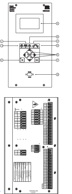
FRONT and SIDE PANEL VIEWS
The front panel HMI (Human Machine Interface) is composed of several elements, including a backlit LCD screen, six (6) pushbuttons and six (6) LEDs. The LCD is the primary interface because it conveys the majority of the information between the DECS-200 and the user/operator. Front panel pushbuttons allow the user to view menu screens and modify the various screen settings and operating conditions. The LEDs annunciate their respective states.
A) 64x128 pixel graphic LCD with backlighting. Primary source for receiving information from the DECS or when locally programming settings. Displays operations, set points, loop gains, metering, protection functions, system parameters and general settings. B) Pre-Position LED – Turns ON at the predefined setting (within the limits of the setpoints) of the current mode. C) Lower Limit LED – Turns ON at the minimum set point value of the current (active) mode. D) Upper Limit LED – Turns ON at the maximum set point value of the current mode. E) Scrolling Pushbuttons – Scrolls UP/DOWN/LEFT/RIGHT through the menu tree or when in the EDIT mode, the LEFT/RIGHT scrolling pushbuttons select the variable to change and the UP/DOWN scrolling pushbuttons change the variable. F) Reset Pushbutton – Cancels editing sessions and can be used as a quick-access to the metering screen. G) Serial Port COM0 – D-type 9 pin connector. This port is dedicated to RS-232 (ASCII commands) communication with a computer terminal or PC running a terminal emulation program such as BESTCOMS™. H) Edit Pushbutton – Enables settings changes. When the EDIT pushbutton is first pushed, an LED on the pushbutton turns ON to indicate the edit mode is active. When changes are complete (using the scrolling pushbuttons) and the EDIT pushbutton is pushed again, the LED turns OFF, indicating the changes are saved. If changes are not completed and saved within five minutes, the edit mode is exited without saving changes. I) Null Balance LED – Turns ON when the inactive modes (AVR, FCR, var, or PF) match the active mode. J) Internal tracking LED – All inactive modes (AVR, FCR, var, or PF) track the active mode to accomplish the bumpless transfer when changing active modes.
-
 Beckhoff C6640-0040 Control Cabinet Industrial PC 7-Slot
 -
 BECKHOFF CONTROL CABINET INDUSTRIAL PC - C6930-1062-0050
 -
 Beckhoff Automation EtherCAT Terminal EK1100 EK1122
 -
 Beckhoff CP6533-0001-0060 IPC
 -
 Beckhoff EK9500 | EtherNet/IP™ Bus Coupler
 -
 Beckhoff CP6202-1047-0050 - An industrial-grade embedded panel computer.
 -
 Beckhoff C6650-0040 Industrial PC
 -
 BECKHOFF CX5230-0185 / 000119805 PLC Module
 -
 BECKHOFF EL4732 | EtherCAT Terminal, 2-channel analog output, voltage, ±10 V, 16 bit, oversampling
 -
 Beckhoff CP6202-0001-0010 Economy Built-In Panel
 -
 Beckhoff AX5206-0000-0202 Digital Compact Servo Drives 2-channel
 -
 Beckhoff CP6606-0001-0020 7-inch Economy Panel PC
 -
 Beckhoff CPU basic module CX2020-0155 + power supply module CX2100-0004
 -
 Beckhoff CP2913-000 Multi-Touch Display
 -
 Beckhoff CP6500-1012-0060 14250369 Control Cabinet
 -
 Beckhoff CP7902-0001-0000 Economy Control Panel with DVI/USB Extended interface
 -
 Beckhoff C6920-0010 Control cabinet Industrial PC
 -
 BECKHOFF C3640-0050 Build-in Industrial PCs
 -
 Beckhoff KL6023-0000 KL6023 EnOcean Wireless-Adapter
 -
 Kollmorgen AKM54G-ANC2DB00 servo motor
 -
 Kollmorgen AKD-P00606-NBCN-0000 Servo Drive
 -
Kollmorgen S200 Series S20350-VTS SERVO DRIVE
-
 KOLLMORGEN AKD-P00606-NBCC-I000 SERVO DRIVE
 -
 Kollmorgen MV65WKS-CE310/22PB Servo Drive Control Module
 -
 Kollmorgen S20360-VTS-021 Servo Drive
 -
 KOLLMORGEN CR06550 High-precision digital servo amplifier
 -
 KOLLMORGEN DBL5N01050-03S-VV0-S40 3-Phase AC Synchronous Brushless Servo Motor
 -
 KOLLMORGEN S70301-NANANA-024 SERVO DRIVE
 -
 Kollmorgen S20360-VTS S200 Series Servo Drive
 -
 Kollmorgen RBE-03011-A00 Brushless Frameless Servo Motor
 -
 KOLLMORGEN AKD-T00306-NBAN-0000 INPUT SERVO DRIVE
 -
 KOLLMORGEN S700 Servo Controller S70302-NANANA
 -
 Kollmorgen AKD-P00607-NBEC-0000 400/480VAC 4.40KVA Servo Drive.
 -
 KOLLMORGEN S70102-NANANA SERVO DRIVE
 -
 KOLLMORGEN AKM21E-ANSNEH02 PM Servo Motor & PRD-AMPE25EB-00 Servo Drive Array
 -
 KollMorgen SC1R06260 Servo Drive 1.4/2.2 KVA 115230 Vac
 -
 Kollmorgen AKD-P00306-NBAN-0000 Servo Drive
 -
Kollmorgen TTB2-2042-3052-A DC Motor Industrial Drive 5.5A 185 oz/in
-
 KOLLMORGEN SERVOSTAR 610-AS SERVO AMPLIFIER_SERVOSTAR610AS_S61001
 -
 KOLLMORGEN PRD-0016400P-10 & PRD-0016600D-30 Axis Control System Modules
 -
KOLLMORGEN Seidel DBL5N01700-03S-000-S40 Servo Motor
-
 Hirschmann RS20-1600M2T1SDAEHH03.1.02 Rail Switch
 -
 Hirschmann BRS30-24TX Industrial Rail Switch
 -
 Hirschmann RSPM20-4T14T1EV9HHS999.9.99 Managed Ethernet Switch
 -
 Hirschmann BELDEN RS40-0009CCCCSDAPHH09.0.14 / RS400009CCCCSDAPHH09014
 -
Hirschmann RS40 Rail Switch RS40-0009CCCCSDAE
-
 Hirschmann BELDEN RS30-0802T1T1SDAP / RS300802T1T1SDAP Fully Managed Layer 2 Compact Rail Switch
 -
 Hirschmann BELDEN RS20-0800M2M2SDAUHH / RS200800M2M2SDAUHH
 -
 Hirschmann EAGLE30-04022O6TT999SCCY9HSE3F Industrial Firewall Router Switch
 -
 Hirschmann RS20-1600T1T1SDAEHH09.0.14 RS20 Rail Mount Ethernet Switch
 -
 Hirschmann EAGLE0200T1T1TDDY90000HHE05.3.03 Industrial Security Router
 -
Hirschmann - BELDEN MIPP-AD-1L9P
-
 HIRSCHMANN RSPM20-4Z64Z6TV9HHS9 942 106-999 RAIL SAFETY SWITCH
 -
 HIRSCHMANN FIBEROPTIC MODULE FIP P/N: OZDFIPG3T
 -
 HIRSCHMANN RS20-1600M2M2SDAUHH Ethernet rack-mounted switch
 -
 HIRSCHMANN BELDEN RS20-0400T1T1SDAEHH04.0.01 / RS200400T1T1SDAEHH04001
 -
HIRSCHMANN MM2-4FXM3 MICE Media Module
-
HIRSCHMANN RS20-0800M2M2SDAE Industrial Ethernet Rail Switch
-
 Hirschmann RS20-2400T1T1SDAP / RS20-2400T1T1SDAPHH05.0.02
 -
 GE MLJ1005B010H00C MLJ Digital Synchromism Check
 -
 ALSTOM MICROTECH DX21-M2 Digital Excitation Controller
 -
HIRSCHMANN BRS20-1200ZZZZ-STCY99HHSES
-
 HIRSCHMANN MM3-4FXM2 MICE Media Module
 -
Hirschmann RSB20-0800T1T1SAABHH 8Port ENet Rail Switch RSB20
-
 Hirschmann MACH102-8TP Ethernet Switch
 -
 SAACKE DDZ-M marine steam pressure atomizer
 -
 SAACKE SKV-A marine rotary cup atomizer
 -
 SAACKE Seavis HMI05e
 -
 Kollmorgen MMC-SD-2.0-230 Servo Drive 100-240VAC 2KW 10A Output 3PH 100-240VAC
 -
 Kollmorgen Servo drive CR10550
 -
 Kollmorgen AKD-P01207-NACN-0054 Servo Driver
 -
 Kollmorgen S406M-CA-036 Servostar
 -
.png) Kollmorgen AKD-B02407-NAAN-0000 Digital Servo Drive
Kollmorgen AKD-B02407-NAAN-0000 Digital Servo Drive -
 Kollmorgen SERVOSTAR S406AM-CA Digital Servo Drive
 -
 KOLLMORGEN SERVOSTAR 603-AS SERVO AMPLIFIER_SERVOSTAR603AS_S60301
 -
Kollmorgen S700 Servo Controller (S70602-NANANA-NA)
-
 Kollmorgen MPK411 controller
 -
 KOLLMORGEN MMC-SD-1.3-460-D Smart Drive
 -
 KOLLMORGEN AKM21C-CKB2AA-00 / AKM21CCKB2AA00 Servomotor
 -
 BECKHOFF AX5106-0000-0200 | Digital Compact Servo Drives 1-channel
 -
 BECKHOFF C3620-0000 INDUSTRIAL COMPUTER (MOTORSHELVES)
 -
 Beckhoff EK1960-0000 TwinSAFE Compact Controller
 -
 Beckhoff C6930-0050 Control Cabinet Industrial PC
 -
 Beckhoff CP7711-0001-0030 Industrial Computer Detection
 -
 Beckhoff CX1001-0111 Embedded PC CPU Module
 -
 Beckhoff C6017-0020 | Ultra-compact Industrial PC
 -
 Beckhoff EK1322 | 2-port EtherCAT P junction with feed-in
 -
 Beckhoff CP2219-0010 Panel
 -
 BECKHOFF C6015-0020 ULTRA COMPACT INDUSTRIAL PC
 -
 BECKHOFF CX2030-0120/Standard CPU Module Embedded PC Windows PLC controller
 -
 Beckhoff CP7721-1090-0020 Panel PC
 -
 Beckhoff PC CPU Module CX5130-0175
 -
 Beckhoff C6920-0050 Control Cabinet
 -
 Beckhoff EL6631 EtherCAT 2-Port Communication Interface, Profinet RT Controller
 -
 Beckhoff CP6202-0001-0060 touch screen panel PC
 -
 Beckhoff CP3916-1002-0000 Multi-Touch Control Panel
 -
 Beckhoff EP1809-0021 | EtherCAT Box, 16-channel digital input, 24 V DC, 3 ms, M8Preferred type
 -
 Beckhoff CX8190 PLC Embedded Industrial PC Ethernet Controller
 -
 Beckhoff CX2100-0914 Power Supply for External
 -
 Beckhoff Automation CP6906-0001-0000 HMI
 -
 Beckhoff EP7342-0002 Module
 -
 Beckhoff CX1020-0112 / CX1100-0910 / CX1020-N010 / CX1100-0003 Windows CPU
 -
 Beckhoff EP7211-0034 EtherCAT Box 1 Channel Motion Interface
 -
 Beckhoff C6240-0030 Control cabinet Industrial PC
 -
 beckhoff motherboard CB1052-0004 CB1052-0004
 -
 Beckhoff AX2006-AS Servo Drive / Variable Frequency Drive
 -
BECKHOFF CP6207-0001-0020 NSMP
-
 Beckhoff C6930-1142-0060 Industrial Computer
 -
 Beckhoff FC7501-0000 interface card
 -
 Beckhoff CX5140-0175 Embedded PC PLC CPU CX5140 Industrial Controller
 -
 Beckhoff CP7802-1100-0010: High-End IP65 Control Panel with DVI/USB Extended Interface
 -
BECKHOFF CP3716-1058-0010 CONTROL PANEL
-
 Beckhoff AX8108-0000 Single-Axis Module
 -
 Beckhoff CU8851-0000 | USB extension, USB Extended 2.0 receiver box
 -
Beckhoff C6017-0030 | Ultra-compact Industrial PC
-
 Beckhoff CX1001-0120/CX10010120.cx1000-n001.cx1000-n000 System Overview
 -
 Beckhoff CPU Module CX5140-0155/4GB CPU Module
 -
 Beckhoff CP6533-0001-005: Built-in Panel PC with High-Definition Multi-Touch Control
 -
 Beckhoff EL5042 | EtherCAT Terminal, 2-channel encoder interface, BiSS® C
 -
 Beckhoff C6920-1080-0040: Premium Control Cabinet Industrial PC
 -
 Beckhoff C6920-0060 | Control cabinet Industrial PC
 -
 Beckhoff Embedded-PC CX5010-1121
 -
 Beckhoff CB3050-0010 Mainboard Motherboard
 -
 Beckhoff PLC module CX1020-0000 Basic CPU module (service phase)
 -
 Beckhoff CP7812-1056-0010 15" Multitouch Display Control Panel
 -
 Beckhoff CX5120-0115 /2GB Controller Module
 -
 Beckhoff CP7201-1000-0000 Industrial Panel PC
 -
 Beckhoff Servo Motor AM8061-0JH1-0000


