
Woodward ESDR 4 Current Differential Protection Relay
ESDR 4
Current Differential Protection Relay
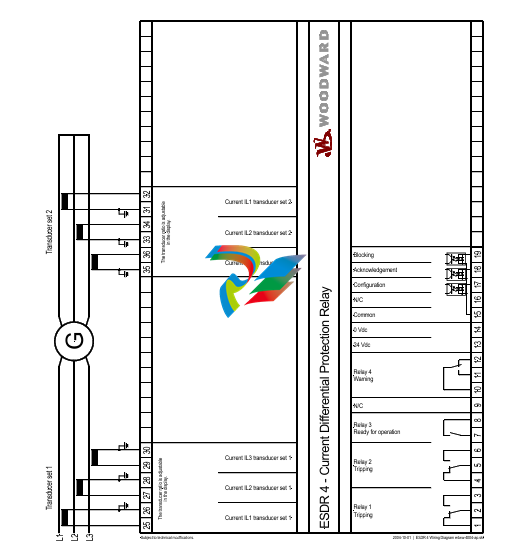
The ESDR 4 is a three-phase current differential protection relay for generators and motors (protected object).
The currents flowing in the individual lines are each measured using a current transformer on both sides of the
protected object. They form the protection area boundary or zone. All two or three-phase short circuits and line
to-earth faults within this protection area are detected by the ESDR 4 as fault currents which initiate tripping.The
unit does not trip if fault currents occur outside the protection zone. In this way, a selective protection is guaran
teed.

The unit monitors six (6) measured currents via isolated inputs. The unit calculates internally the restraint current
(Is) and the differential current (Id) separately for each phase. The actual values of the calculated parameters (Dif
ferential current Id und Restraint current IS) are shown on the display either as absolute values or as a percentage
of the generator rated current (selectable in locked input mode).
Theoretically the currents Ia and Ib are equal, both in fault-free operation and outside the protection zone (Figure
4-1-a).The difference is zero and the differential protection does not initiate. However, in practice current differ
entials do occur (= spurious currents), even in fault-free operation. They result, for example, from summation or
phase angle errors in the CTs, which are influenced by deviating burden values. These spurious currents remain
small inside the operating range, but increase with increasing load and are especially high when one or more CTs
become saturated (e.g. in the case of an external short circuit). In order to prevent a tripping of the relay due to
spurious currents, the trigger threshold is not held statically constant but increases in relation to the restraint cur
rent Is. Spurious currents need to be taken into account when adjusting the trip characteristic.
When a fault occurs inside the protection area (Figure 4-1-b), unequal currents flow in the CTs, which result in a
current differential. If this exceeds the differential protection threshold, the relay will trip.
Monitoring of the Differential Current
The monitoring of the differential current is carried out in two stages..
The first monitoring level serves as a warning and can be enabled or disabled. Should the adjustable warning
characteristic be exceeded, a text appears in the display and a relay contact is enabled. The pick-up time and the
dropout delay of the relay output are adjustable. The warning stage of the monitoring is auto-resetting.
The second stage of monitoring (main stage) serves to initiate tripping. In contrast to the first stage, it offers the
possibility to monitor the overstepping of an adjustable tripping characteristic (Id < In) and additionally, a fixed
tripping-threshold of 100%, relative to the generator rated current (Id > In). The trigger-delay for each limit value
may be independently adjusted, thus allowing a shorter triggering time at higher differential currents. When one
or both tripping characteristics are exceeded, a text display is initiated and two relay contacts are energized. The
tripping characteristics possess a 2% hysterisis relative to the generator rated current. .
The signal relay is only automatically reset if the function "automatic reset relay" in the Entry field on the screen
is configured to "on". Otherwise, the resetting is carried out by pressing the "Clear" button on the front of the
unit or via the discrete input terminal 18 "reset".
The two monitoring levels can also be used to change the characteristics of the control function (stage 1: small
value and a long time; stage 2: high value and a short time)
Tripping Characteristic
The following figure shows the tripping and warning characteristics (with sample values for X12. Y1.and Y2). It
represents the tripping and warning thresholds (Y) relative to the restraint current (X) The positions of the corner
points are determined by the coordinates P (X12/Y2) and P (X12/Y1). The selection of these positions is depend
ent on the generator being protected. The following gives the ranges of tripping and warning thresholds:
IS / IN
IS / IN
IS / IN
0 to X12
X12 to 5 × IN
> 5 × IN
The threshold Id is independent of the restraint current..
The threshold Id is dependent on the restraint current. A change of 100% in the
restraint current causes an increase of 10% in the tripping threshold.
The threshold Id stays constant at 85%.
Different characteristics can be chosen for the first and second monitoring levels, whereby the horizontal position
(X-coordinate) is valid for both stages. The vertical position (Y-coordinate) can be chosen separately for each
monitoring level. This results in a fixed difference in thresholds of the first and second monitioring levels for
each restraint current Is.
Control Inputs
Configuration
Terminal 17
Acknowledgement
Terminal 18
Blocking
Terminal19
Relays
Tripping (relay 1)
Terminals 1/2/3
Tripping (relay 2)
Terminals 4/5/6
Warning (relay 4)
Terminals 11/12/13
Ready for operation
(relay 3)
Terminals 7/8
When this input is energized, the unit locks into Configuration mode and stays in this
mode until the terminal is de-energized.
If this input remains energized for at least 1 s, the faults detected in monitoring
level 2 are reset. This means that the relays will be de-energized and the text display
will be deleted from the screen as long as the monitored currents are not exceeding
the configured threshold level.
When this input is energized, the differential protection is disabled.This means that
the differential current is not monitored, no relay can be enabled and no text is dis
played.
This relay becomes enabled when the unit detects threshold limit 2 (main stage) has
been exceeded. The configured differential current characteristics and delay time will
determine how relay 1 functions.
This relay becomes enabled when the unit detects threshold limit 2 (main stage) has
been exceeded. The configured differential current characteristics and delay time will
determine how relay 2 functions.
This relay becomes enabled when the unit detects threshold limit 1 has been ex
ceeded. The configured differential current characteristics and delay time will deter
mine how relay 4 functions.
This relay is enabled when the unit is operational and the differential current is being
monitored. The relay becomes disabled if the monitoring is deactivated through any
of the following reasons:
• the internal self-monitoring has detected a malfunction of the unit. A correct func
tioning of the unit cannot be guaranteed and corrective action may be necessary.
• the set values for parameter "CT-ratio" or parameter "Generator Current" are out
side the permissible limits (see page 19).
• the digital input "Blocking" is energized.
• the parameter "Monitoring" is configured to "Off".
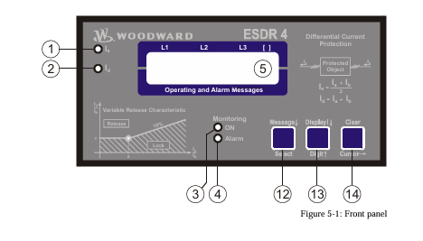
When in configuration mode (simultaneous pressing of "Digit↑" and "Cursor→"), the configuration screen can
be advanced by pressing the "Select" button. Should there be no entry, parameter change or other action for 60
seconds, the unit will automatically revert into Automatic mode.
During the configuration mode, the monitoring function is still active. This means inevitably, that while adjusting
parameters during operation, it is possible to cause a tripping of the relay.
adjust settings
[press "SELECT"]
Configuration mode "Select" button
Pressing the "Select" key activates the configuration mode, and the following pa
rameters can be enabled or changed within the given limits. Please you note that as
you advance through the configuration screens, by configuring some parameters as
"ON", additional screens must be configured relating to that parameter. If the pa
rameter is configured as "OFF", the additional screens will be disabled and not dis
played.
Software version
Software version
Displays the software version.
SPRACHE/LANGUAGE ----------------
Language selection english/german
The screens can be displayed in German or English.
curr. transform.
ratio 0000/x
CT-Ratio Selection 10 to 6.000/{x} A
The Ratio of the CTs being used is entered here. The CTs should be selected so that
in fault-free operation at generator rated current, at least 60 % of nominal current
flows in the CT-secondary. Failure to use properly a sized CT-Ratio leads to loss of
resolution and inaccuracies in the monitoring functions.
generator nomin.
current 0000A
Generator rated current 5 to 6.000 A
This value is used as reference value for the calculation and display of restraint cur
rent and differential current. The entered value of generator current must be at least
60% of the nominal current of the CT and must not exceed the entered value of CT
nominal current.
Example CT-Ratio 500/5 A
Range of Generator rated current 300 A to 500 A.
If the nominal value is less than 50% of the transformer ratio, the message "Wrong
Entry" will be displayed on the screen in Automatic mode and the unit will de
activate monitoring functions (the Monitoring LED goes out).
automatic reset
relay ON
Automatic reset of the relay ON/OFF
Applies only to monitoring level 2 (tripping).
Monitoring level 1 (warning) always Auto-resets.
ON................The relays de-energize automatically when the fault is no longer pre
sent. The screen input "Automatic reset of error text" determines
what happens to the Alarm-text in the display.
OFF..............The relays remain energized until they are reset.
monitoring
ON
Monitoring ON/OFF
ON................Monitoring of the differential current is active and the follow
ingscreens of this option are displayed.
OFF..............The monitoring is de-activated and the following screens are not dis
played.
release limit
Is/In X=000%
Trigger Value IS/IN (X12) 50 to 300 %
Definition of the threshold characteristic for the monitoring of levels 1 and 2.
This value determines the horizontal position (X12-coordinates of points
P [X12/Y1] and P [X2/Y2]) of the corner points of the Warning and Tripping char
acteristics.
release limit
Id/In Y=000%
Limit valueId
This value determines the vertical position (Y2-coordinate) of the corner point
P [X12/Y2] of the tripping characteristic (monitoring level2).
pick-up t. Id>IN
release 0.00s
Relay enable delay time for Id>IN (monitoring level 2) 0.04 to 3.00 s
If the differential current surpasses the generator rated current without interruption
over this time period, a fault condition for exceeding the threshold limit will be ini
tiated.
pick-up t. Id
release 0.00s
Relay enable delay time for Id
If the differential current surpasses the adjusted trigger threshold without interrup
tion over this tme period, a fault condition for exceeding the threshold limit will be
initiated.
release time
release 0.00s
Relay disable delay time (monitoring level 2) 0.10 to 3.00 s
Only visible when the screen "Automatic reset of the relay" is configured to
ON .
If the differential current value which initiated the fault condition should fall 2% or
more below the trigger threshold limit and remain uninterrupted for the period of
time configured here, the fault condition will be terminated and the relay output
and the fault text will be reset.
automatic reset
error text ON
Automatic reset of error text ON/OFF
Only visible when the screen "Automatic reset of the relay" is configured to
ON
ON................The displayed fault text will be automatically deleted, when the fault
conditions are no longer detected.
OFF..............The displayed fault text must be deleted manually, and can only be
done when fault conditions are no longer detected.
automatic reset
error text 00s
Delay for automatic reset of error text 1 to 60 s
Only visible when the screens "Automatic reset of the relay" and "Automatic
reset of error text" are configured to ON
The fault text will automatically delete, when the fault conditions are no longer de
tected for the time period set here.
warning
ON
Warning (monitoring level 1) ON/OFF
ON................The adjustable warning characteristic is being monitored and the fol
lowing screens of this option are displayed.
OFF..............The adjustable warning characteristic is not being monitored and the
following screens of this option are not displayed.
warning limit
Id/IN Y=00.0%
Trigger value Id/IN (monitoring level1. Y1) 3.0 to 40.0 %
Only visible when the screen "Warning" is configured to ON.
This value determines the vertical position of the corner point of the warning char
acteristic. The horizontal position (X12) is identical with that of the trip character
istic. Usually the warning limit is lower than the trip limit value.
pick-up time
warning 0.00s
Enable delay time of the "warning" relay (monitoring level1) 0.04 to 3.00 s
Only visible when the screen "Warning" is configured to ON.
If the differential current exceeds the warning threshold curve without interruption
over this time period, the control recognizes that the warning limit has been ex
ceeded.
release time
warning 0.00s
Relay disable delay time (monitoring level 1) 0.10 to 3.00 s
Only visible when the screen "Warning" is configured to ON
If the differential current value which initiated the warning should fall 2% or more
below the trigger threshold limit and remain uninterrupted for the period of time
configured here, the fault condition will be terminated and the relay output and
fault text will be reset.
display value
Id [-]
Display – measured value Id in [%] / [A]
[%]...............The percentage of the rated generator current that is measured is dis
played on the screen.
[A]:...............The measured absolute values are displayed on the screen.
display value
IS [-]
Display – measured value IS in [%] / [A]
[%]...............The percentage of the rated generator current that is measured is dis
played on the screen.
[A]:...............The absolute measured values are displayed on the screen.
-
 Hirschmann M1-8SFP Switche
 -
 Hirschmann Industrial Ethernet Ruggedized Switch MACH1000 Family
 -
 Basler Electric, Solid State Protective Relay, BE1-60
 -
BASLER ELECTRIC SR4A-2B15B3A Static Voltage Regulator
-
.png) BASLER ELECTRIC EXCITER DIODE MONITOR EDM-200
BASLER ELECTRIC EXCITER DIODE MONITOR EDM-200 -
.png) BASLER ELECTRIC DECS125-15-B2C5 DIGITAL EXCITATION CONTROL SYSTEM V 2.0.9
BASLER ELECTRIC DECS125-15-B2C5 DIGITAL EXCITATION CONTROL SYSTEM V 2.0.9 -
 BASLER ELECTRIC BE1-851 OVERCURRENT PROTECTION RELAY MECHANISM
 -
 Basler Electric BE1-51A / BE151A
 -
 Basler Electric BE1-40Q Loss of Excitation Relay
 -
 Basler Electric BE1-87G Variable Percentage Differential Relay
 -
 Basler Electric BE1-11 Protection System I5A3M2P2N0EA00
 -
 BASLER ELECTRIC DECS-200-1C Digital Excitation Control System
 -
 Basler Electric / Kohler BE1-11g Generator Protection Relay G5A3M2J2N0E000
 -
BASLER ELECTRIC DECS125-15 DIGITAL EXCITATION CONTROL SYSTEM
-
 BASLER ELECTRIC BE1-951 OverCurrent Protecton System
 -
Basler Electric DECS-200-1L Digital Excitation Control System
-
 Basler Electric DGC-2020HD-5NS1DNSBA Digital Genset Controller -
 -
 BASLER ELECTRIC BE1-81T1EE1WA0N1F / BE181T1EE1WA0N1F
 -
 BASLER ELECTRIC BE1-25M1EA6PN5R1F / BE125M1EA6PN5R1F
 -
 BASLER ELECTRIC DECS-250-LN1SN1N DIGITAL EXCITATION CONTROL SYSTEM
 -
Basler Electric DECS-250-CN2CN 1N Digital Excitation Control System Unit
-
 BASLER ELECTRIC DECS-300-C0N0 DIGITAL EXCITATION CONTROL SYSTEM
 -
 BASLER ELECTRIC BE1-87T-A1E-A1J-D0S1F / BE187TA1EA1JD0S1F
 -
BASLER ELECTRIC BE1-11-G6D1M0J2P0E000 Protection System
-
 BASLER ELECTRIC BE1-GPS100-E4N1H1N GENERATOR PROTECTION SYSTEM
 -
 Jaquet Relay card (Auxiliary module) FTV 3090 377Z-03985
 -
 Jaquet Trip Chain Control card FTBU 3034 377Z-05030
 -
 Jaquet with input card -E04 FTFU 3024 -E04 377Z-05855
 -
 Jaquet with input card -E03 FTFU 3024- E03 377Z-03983
 -
 Jaquet FTFU 3024- E02 377Z-03982 with input card -E02
 -
 Jaquet FTFU 3024-E01 377Z-03981 with input card -E01
 -
 Hirschmann RS20-2400T1T1SDAE Industrial Managed Ethernet Switch
 -
 Hirschmann BELDEN EAGLE30-04022O6TT999SCCV9HSE3F
 -
 Hirschmann MM3-2FXS2/2TX MICE Media Module
 -
 Hirschmann RS20-1600M2M2SDAPHC08.0.05 Industrial Managed Switch
 -
 Hirschmann OZD Profi 12M G12-1300 PRO Fieldbus Repeater
 -
 Hirschmann SPIDER 4TX/1FX-ST EEC Industrial Ethernet Switch
 -
 Hirschmann MM2-2FXM3/2TX1 MICE Media Module
 -
 Hirschmann RS20-2400M2M2SDAPHC09.0.14 Industrial Switch
 -
 Hirschmann RS20-0400M2M2SDAEHC07.1.05 OpenRail Switch
 -
 Hirschmann OZD Profi 12M G12-EEC Fieldbus Repeater
 -
 HIRSCHMANN MDA422-1/2-3.5c-23/46 sensor
 -
Hirschmann RS30-2402T1T1SDAUHC Managed Industrial Switch
-
 Hirschmann OZD GENIUS G12 Industrial Switche
 -
 Hirschmann OZD 485 G12-1300 PRO Fieldbus Repeater
 -
 Hirschmann MM2-2FXM2 MICE Media Module
 -
 Hirschmann RS20-1600S2T1SDAUHC Managed Industrial Switch
 -
 Hirschmann MS20-0800SAAEHH04.2.04 MICE Switch
 -
 Hirschmann SPIDER 4TX/1FX EEC Unmanaged Industrial Switch
 -
 HIRSCHMANN MS4128-L3P EEC Managed Industrial Ethernet Switch
 -
 HIRSCHMANN RS20-0400M2T1SDAPHC08.0.01 Managed Switch
 -
 ETEL EA-S0M-400-40/80A-0000-00 AccurET Modular Power Supply
 -
 ETEL EA-B0I-0-0-0000-00 Backplane Interface Board
 -
 ETEL EA-P2M-400-15/40A-0100-00 Position Controller
 -
ETEL EA-P2M-400-15/40A-0000-00 Position Controller
-
 ETEL EA-P2M-400-10/20A-0100-01 Position Controller
 -
 ETEL EA-P2M-400-10/20A-0000-01 Position Controller
 -
 ETEL EA-P2M-400-5/10A-0100-01 Position Controller
 -
 ETEL EA-P2M-048-2.5/5A-0000-01 Modular Position Controller
 -
 ETEL EA-S0M-300-40/80A-0000-00 Power Supply Module
 -
 ETEL EA-P2M-300-07/15A-0100-01 Position Controller
 -
 ETEL EA-P2M-300-07/15A-0000-01: Modular Position Controller
 -
 ETEL EA-P2M-300-4/7.5A-0100-01 Overview
 -
 Basler Electric MOC2. Motor Operated Potentiometer
 -
 Basler Electric BE1-11 RTD Module, Resistance Temperature Detector
 -
 Basler Electric RDP-110C, Remote Display Panel
 -
 Basler Electric VRM-2020. Voltage Regulation Module
 -
 Basler Electric IDP-1500. Interactive Display Panel
 -
 Basler Electric AEM-2020. Analog Expansion Module
 -
 Basler Electric IDP-2020. Interactive Display Panel
 -
 Basler Electric CEM-2020. Contact Expansion Module
 -
 Basler Electric CEM-125. Contact Expansion Module
 -
 Basler Electric BE2000E, Digital Voltage Regulator
 -
 Basler Electric SMC-150. Synchronous Motor Controller
 -
 Basler Electric AVC125-10. Voltage Regulator
 -
 Basler Electric BE1-25. Sync-Check Relay
 -
 Basler Electric DGC-2020ES, Digital Genset Controller
 -
 ETEL EA-P2M-400-5/10A-0000-01 Position Controller
 -
 Basler Electric BE1-64F, Ground Fault Relay
 -
 Basler Electric BE1-79M, Multi Shot Reclosing Relay
 -
 Basler Electric BE1-81O/U, Digital Frequency Relay
 -
 Basler Electric BE1-87B, High Impedance Bus Differential Relay
 -
 Basler Electric BE1-79A, Reclosing Relay
 -
 Basler Electric BE1-27. BE1-59. BE1-27/59. Voltage Relay
 -
 Basler Electric SMC-250. Synchronous Motor Controller
 -
 Basler Electric SGC-250N, Synchronous Generator Controller
 -
 Basler Electric SGC-250. Synchronous Generator Controller
 -
 Basler Electric BE1-50/51 Plug and Play and Retrofit Relays
 -
 Basler Electric DECS-2100. Digital Excitation Control System
 -
 Basler Electric DECS-250E, Digital Excitation Control System
 -
 Basler Electric BE1-700V, Voltage Only Digital Protective Relay
 -
 Basler Electric DECS-250. Digital Excitation Control System
 -
 Basler Electric DECS-450. Digital Excitation Control System
 -
 Basler Electric DECS-150. Digital Excitation Control System
 -
 Basler Electric ES-49. Temperature Relay
 -
 Basler Electric ES-81O/U, ES-81O,ES-81U Overfrequency Relay
 -
Basler Electric ES-74V, DC Voltage Sensing Relay
-
Basler Electric ES-27/59. Under/Overvoltage Relay
-
 Basler Electric ES-27. Undervoltage Relay
 -
 Basler Electric ES-25. Sync-Check Relay
 -
 Basler Electric ES-47, ES-47N Phase Sequence Relay
 -
Basler Electric ES-37.ES-37/51 Undercurrent Relay
-
 Basler Electric ES-32. Reverse Power Relay
 -
Basler Electric ES-59. Overvoltage Relay
-
 Basler Electric ES-55. Power Factor Relay
 -
 Basler Electric DGC-2020HD, Digital Genset Controller
 -
 Basler Electric BE1-FLEX, Protection, Automation, and Control System
 -
 Schneider GUTOR OC0935 Power Factor Sampling Board
 -
 Schneider GUTOR OC0922 Analog Signal Isolation Board
 -
 Schneider GUTOR OC0908 Battery Voltage Detection Board
 -
Schneider GUTOR OC0947 Temperature / IGBT Sampling Board
-
 Schneider GUTOR OP2601 Communication Expansion Board
 -
 Schneider Electric GUTOR OP2312 bypass control board
 -
 Schneider Electric GUTOR OP2130 Cooling Fan Monitoring & Control Board
 -
 Schneider Electric GUTOR OP2010 Battery Test Board / Battery Management Diagnostic Card
 -
Schneider Electric GUTOR OP2552 Three-phase Power Connection Board Assembly
-
 Schneider Electric GUTOR OP1922A Parallel Control Board / Load-Sharing Synchronization Module
 -
 Schneider Electric GUTOR OP6290B Inverter Feedback Acquisition Board / Signal Scaling Module
 -
Schneider GUTOR OP6280 Basic Signal Board
-
Schneider Electric GUTOR OP2456 / OP2456B Main control board
-
 Schneider Electric GUTOR OP2452 Power Plug-in Panel
 -
 Schneider Electric GUTOR OP2450 Parallel Communication Board
 -
Schneider Electric GUTOR OP2406 Interface Fuse Monitoring Board
-
 Schneider Electric GUTOR OC0919 High-Power Semiconductor Module
 -
 Schneider Electric GUTOR OP6281A System Logic Interface Board
 -
 Schneider Electric GUTOR OP6285A Power Signal Acquisition Board
 -
 Schneider Electric GUTOR OP2438 Fan Monitor & Drive Protection Board
 -
Schneider Electric GUTOR OP2446 Main Control CPU Board


