
HoneywellEXPERION PKSSeries C I/O User's Guide EPDOC-X126-en-A November 2019
ABOUT THIS GUIDE
The procedures in this guide are intended to give you the ability to perform basic tasks with the
Series C I/O such as configuring hardware devices, continuous control strategies. Respective
forms are displayed to illustrate a procedure/concept only.
1.1 Revision History
Revision Date Description
A November 2019 Initial release of the document.
l Intended audience
l Prerequisite Skills
l References
l Terms and acronyms
1.2 Intended audience
This guide is intended for the following users:
l Persons responsible for system planning, initial hardware installation, and control strategy
configuration
l Operators who help to maintain control system operations on a day-by-day basis
l Service persons responsible for routine maintenance of control hardware, and who diagnose
and repair faults.
1.3 Prerequisite Skills
It is assumed that you should have some knowledge of Experion control systems and experience
of working in a Microsoft Windows environment.
1.4 References
Listed here are the documents that contain general information for planning and implementing
control hardware and network communications in your Experion system:
Control Hardware Planning Guide - Provides general information to assist you in planning
and design of control hardware in an Experion system. Control hardware includes C200
Controllers, Series A Chassis I/O and FIMs, also, all I/O families, (except Series C I/O). It
includes some supervisory network considerations for general reference.
l C300 Controller Guide - This guide provides information that will assist you in planning and
designing activities, as well as the installation, operation, and troubleshooting of Series C300
Controllers in an Experion system.
l Series C Fieldbus Interface Module (FIM) User Guide - Provides planning and implementation
guide for the Series C Fieldbus Interface Module.
l Fault Tolerant Ethernet Overview and Implementation Guide - Provides basic installation
instructions and configuration requirements for a Fault Tolerant Ethernet (FTE) network and
its components.
l Fault Tolerant Ethernet Installation and Service Guide - Contains instructions for installing
and configuring a Fault Tolerant Ethernet (FTE) node. The guide includes troubleshooting
and service information for an FTE node.
l Fault Tolerant Ethernet Bridge Implementation Guide - Provides information for
implementing a Fault Tolerant Ethernet supervisory network through the FTE Bridge module.
It includes module installation, configuration, operation and service data.
l Process Manager I/O Troubleshooting and Maintenance Guide - Guide features notification
messages (soft fail codes and hard fail codes), service procedures and parts lists for PM I/O
control hardware.
1.5 Terms and acronyms
The following table summarizes the terms and type representation conventions used in this guide.
Term/conventions Meaning Example
Click Click left mouse button once. (Assumes cursor is
positioned on object or selection.)
Click the Browse
button.
Double-click Click left mouse button twice in quick succession.
(Assumes cursor is positioned on object or selection.)
Double click the
Station icon.
Drag Press and hold left mouse button while dragging cursor to
new screen location and then release the button.
(Assumes cursor is positioned on object or selection to be
moved.)
Drag the PID
function block
onto the Control
Drawing.
Right-click Click right mouse button once. (Assumes cursor is
positioned on object or selection.)
Right-click the
AND function
block.
<F1> Keys to be pressed are displayed in angle brackets. Press <F1> to view
the online Help.
<Ctrl>+<C> Keys to be pressed together are displayed with a plus sign. Press <Ctrl>+<C> to
close the window.
File->New Shows menu selection as menu name followed by menu
selection
Click File->New to
start new drawing.
>D:setup.exe< Data to be keyed in at prompt or in an entry field. Key in this path
location
>D:setup.exe<.
SERIES C I/O PURPOSE
Series C I/O Modules, along with I/O Termination Assemblies (IOTAs), perform module diagnostics
input and output scanning and processing on all field I/O data and events. To allow a more
efficient use of Controller resources, I/O processing is performed separately from control
processing functions so that:
l I/O sample rates are completely independent of I/O quantity, controller loading, processing,
and alarming
l allows more efficient use of advanced Control Processor capability, and
l provides for future I/O expansion.
l Comparing Process Manager I/O and Series C I/O
l What is Series C I/O?
l Series C Pulse Input Module (SCPIM)
l What is Universal Input/Output (UIO) Module?
l What is Low Level Analog Input (LLAI) Module
l Overview of the Universal Horizontal Input/Output (UHIO)
2.1 Comparing Process Manager I/O and Series C I/O
The following list compares previous features of the Process Manager I/O and the Series C I/O:
l Non-Volatile Memory:
o In the PM, memory was maintained over a power cycle within the I/O card itself.
o With the Series C I/O, the configuration memory information is restored from the
C300 controller at power-up of the I/O Module.
l IOL - The Series C I/O link runs at twice the speed of the PMIO I/O Link. Each C300 I/O Link
can be configured to provide Series-C or PMIO link speeds.
l Series C I/O fully supports HART I/O. This includes the use of Secondary HART Variables as
control parameters.
l Separation of Primary from Secondary modules:
o In the PM, the Primary and Secondary I/O Electronics modules could be separated,
placed in different cabinets, and/or powered by different power systems.
o Series C I/O does not have this capability.
l Series C permits Zone 2 mounting of the Controller and I/O
l In PMIO, the configuration memory is maintained only if a battery backup is installed.
2.2 What is Series C I/O?
The Experion Series C I/O modules are an expanding family of traditional and special functio
input/output signal interface devices. They supports local software configuration. These I/O
modules share the same form factor as the C300 Controller and reside on the same type of
common mounting system as other Series C components.
2.2.1 What is Series C I/O Mark II?
Series C Mark II is an enhancement to the existing Series C platform in terms of IO modules,
related IOTAs, IO link, power supply, power distribution, and cabinet infrastructure, making it a
more cost-effective solution than the earlier version. The design style continues to be the same.
2.2.2 Supported Series C Mark II I/O modules
ATTENTION
Series C Mark II cannot support any PM I/Os.
C300 IOLINK block parameter IOLINKTYPE is used to determine if the IOLINK supports
Series C Mark II I/O.
IOM model
names
IOM block
name
Description No. of channels
supported
CC-PAIH01 AI-HART High Level Analog Input with HART (4)
IOM
16
CC-PAOH01 AO-HART Analog Output with HART (4) IOM 16
DC-PDIL51 DI-24 Digital Input 24V IOM w/o OWD 32
DC-PDIS51 DI-SOE Digital Input SOE IOM 32
DC-PDOD51 DO-24B Digital Output 24V Bussed Out IOM w/o
RB
32
DC-PDIS51 DI-SOE Digital Input SOE IOM 32
CC-PAIM51 AI-LLAI Low Level Analog Input Mux 16
CC-PAIH51 AI-HART AI HART IOM , R2 16
CC-PAIN01 AI-NON-HART AI IOM NON-HART 16
CC-PAOH51 AO HART AO HART IOM, R2 16
CC-PAON01 AO-NON-HART AO NON-HART IOM 16
Series C Pulse Input Module (SCPIM)
The Experion Series C PIM is an interface between C300/CN100 Controller that enables highaccuracy pulse counting of pulse streams from rotating machinery such as turbines, flow meters,
and densitometers. High-accuracy and repeatable measurement capability make the PIM well
suited for metering and custody transfer applications.
The PIM has eight input channels. Out of the eight channels, some may be single consuming one
channel or dual consuming 2 adjacent channels. The last 2 channels (channel 7 and channel 8)
can also be configured as distinct Fast Cutoff using the two output channels on the module.
Each input channel has a 32-bit counter to perform pulse counting and frequency calculation. In
addition, when these channels are configured as single input channels, these eight channels also
have a second 32-bit timer for pulse period and pulse width measurement.
Features of SCPIM
The following are some of key the features of SCPIM.
l Supports IOM redundancy.
l Supports redundant module communications with the controller via IO link.
l Supports simulation with SIM-C300/SIM-CN100 – The input value can be substituted by a
program and/or UniSim using the SIMVALUE parameter.
l Supports high accuracy frequency, period, and pulse width measurement.
l Provides hardware support for Meter Suite applications.
l Provides connections to power field devices or pulse pre-amplifiers.
l Supports pulse multiplexing that enables good pulses from a dual pulse input pair to be copied
to the Prover output interface.
l Supports Dual Pulse Integrity in accordance with ISO6551:1996 Level A, which is required to
support interfacing of custody transfer meters with pulse outputs.
l Provides the flexibility of configuring the eight input channels as single input, dual input, or a
combination of both single and dual input channels . For example you can configure the
channels as;
o 2 single input channels, 3 dual input channels or
o 6 single input channels, 1 dual input channels.
For information on PIM specifications, refer to the Specifications document available on the
Honeywell Online Support site.
Comparison between Series A and Series C PIM
The following table lists some of the differences between the Series A and Series C pulse input
modules.
Series C PIM Series A PIM
Shares the same form factor as the Series
C I/O family.
Requires two form factors to use with C300
controller; series A for the Pulse Input and the series
C form factor for the controller and other I/O
modules.
Supports IOM redundancy. Does not support IOM redundancy.
Supports Dual Pulse Integrity to support
interfacing of custody transfer meters with
pulse outputs.
Does not support Dual Pulse Integrity.
Supports pulse multiplexing that enables
good pulses from a dual pulse input pair to
be copied to the Prover output interface.
Does not support pulse multiplexing.
Supports pulse length measurement in all
channels.
Does not support pulse length measurement in the
last two channels.
Supports configuration of all eight
channels through use of PICHANNEL
block.
Needs two blocks for configuring channels:
l Pulse Input Channel block for configuring the
first six channels.
l Pulse Input Channel with Fast Cutoff block for
configuring the last two channels.
The last two channels can be configured as
Pulse Input channel types or Pulse Input
with Fast Cutoff channel types.
The last two channels can be configured only as
Pulse Input with Fast Cutoff channel types.
2.4 What is Universal Input/Output (UIO) Module?
With R410, an Universal Input/Output (UIO) module is introduced that enables you to configure
the input/output channels within a single IOM. The UIO module supports 32 channels. Each
channel can independently be configured as one of the following types.
l Analog Input channel (0-20mA or 4-20mA)
l Analog Output channel (4-20mA)
l Digital Input channel (with or without broke-wire detection)
l Digital Output channel (with or without broke-wire detection)
The UIO channels and device blocks are compatible with existing Series C AI, AO, DI, and DO
channels and blocks. In addition, each analog channel in the UIO module can be configured to
support HART input/output functionality.
l Features of UIO
l UIO features
l Differences between UIO channels and existing Series C AI, AO, DI, and DO modules
Features of UIO
The following list illustrates the key features of the UIO module
l Supports optional IOM redundancy.
l Supports simulation with SIM-C300/SIM-CN100.
l Supports HART functionality for AI and AO channel types.
l Supports multiple channel type configurations.
l Operates in an extended temperature range (-40 degree Celsius to +70 degree Celsius).
l Supports the ability to monitor the current, minimum, and maximum temperatures.
l Supports remote control when it is located within 10 kilometers from the controller.
l Supports open wire detection.
l Supports DO channel ganging from R430 onwards.
l Supports pulse counting functionality from R430 onwards.
NOTE
To use an AI HART channel in conjunction with the analog mode, it must be used on
channels 13 through 20 only. If HART is used on any of the voltage inputs, it can cause an
unstable analog PV value. The HART digital value will be unaffected.
NOTE
For information about UIO specification, refer to the latest Specification and Technical
document available on the Honeywell Online Support site.
UIO features
Support for DO channel ganging
The UIO-DO channel is now enhanced to support ganging for enabling the delivery of more
current output to the field (maximum current output of up to 2.0 Amperes). This is accomplished
using the existing UIO hardware. DO channel ganging simply requires software configuration of
up to four adjacent DO channels of the UIO module and appropriate channel wiring accordingly.
ATTENTION
l Up to four DO channels can be ganged at a time.
l UIO-channel 32 cannot be ganged with channel 1.
Support for pulse counting functionality
The UIO module DI channel is capable of providing pulse counting functionality. However, only
four DI channels (channels 15, 16, 17 and 18) support pulse counting functionality.
The UIO-DI channel pulse counting supports counting up to 10 KHz of input pulse frequency.
The UIO DI channel configuration consists of simply setting the Digital Input Type parameter to
“Accum” from the Configuration tab of the DI channel.
Differences between UIO channels and existing Series C AI, AO,
DI, and DO modules
The following table lists some of the differences between the UIO and the existing Series C AI, AO,
DI, and DO modules.
UIO module Series C AI, AO, DI, and DO modules
Supports temperature range between -40
degree Celsius to +70 degree Celsius
Supports temperature range between 0 degree
Celsius to +50 degree Celsius
Supports multiple channel type configuration Supports unique channel type configuration
2.5 What is Low Level Analog Input (LLAI) Module
Starting with R430, a new Series C compliant Low Level Analog Input (LLAI) Module is introduced
and designed to operate with the low voltage devices such as Thermocouples and RTDs. The AILLAI module supports 16 channels and accepts temperature inputs in the range of millivolts (mV).
This AI-LLAI module is identical to the existing Series C AI-LLMUX module except that the number
of channels supported by the AI-LLAI module is reduced to 16 channels. Unlike the AI-LLMUX
module, the field inputs can be directly connected to the AI-LLAI IOTA since it has its own IOTA. In
addition, the AI-LLAI module supports a new RTD input type, that is, CU50Rtd. A new library is
introduced in the standard library as "AI-LLAI."
2.5.1 Features of AI-LLAI
The following are some of the key features of AI-LLAI.
l Supports up to 16 RTDs or Thermocouple inputs.
l Operates in an extended temperature range (-40 degree Celsius to +70 degree Celsius).
l Supports a new RTD input type, CU50Rtd.
l Supports configurable Open Thermocouple Detection (OTD).
l Supports 1 second PV scanning with OTD protection.
l Supports N type thermocouple.
NOTE
AI-LLAI module does not support the following features.
l Remote cold junction capability
l User defined table
Overview of the Universal Horizontal Input/Output
(UHIO)
The Universal Horizontal Input/Output (UHIO) enables the replacement of the TDC 2000 Basic
Controllers (CB) and Extended Controllers (EC) with the Experion Series C controllers and
Universal I/Os. To enable mounting in the existing cabinets, new IOTAs are designed for the C300
Controller, Control Firewall, and the Universal I/O module such that it can fit into the space of the
CB and EC modules. However, the existing TCBxx terminal panel, and the field wiring to the TCBs
are retained. Note that different IOTAs are required for the UIO and UIO-2 modules. Either IOTA
will screw onto the back panel.
The introduction of the UHIO hardware allows customers to migrate their Hiway-based control
system to the FTE-based Experion Series C control system.
The following figure is an example of CB/EC rack that is replaced with the Experion Series C
controllers and Universal I/Os.
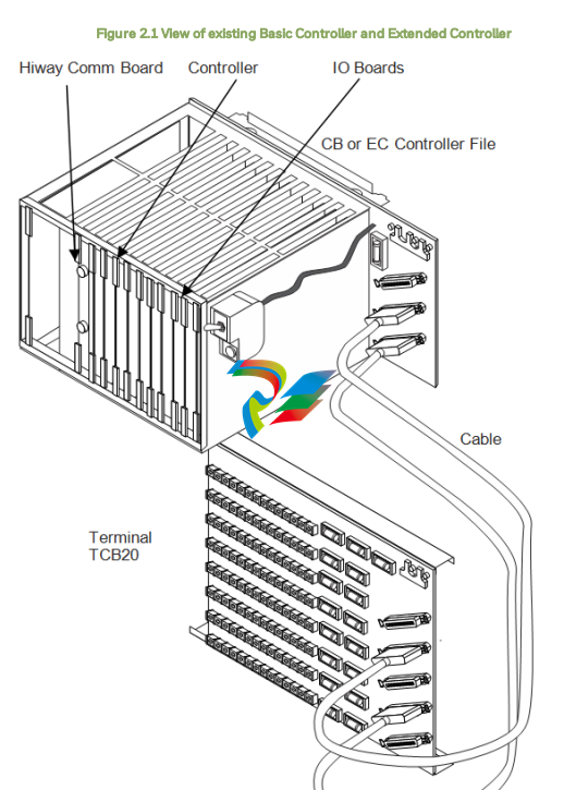
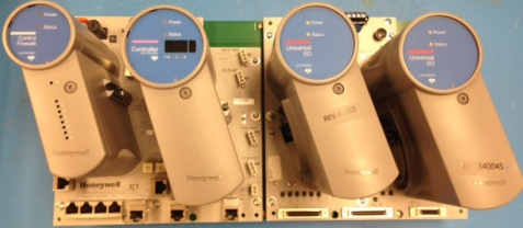
In these figures, the following components are shown.
l Control Firewall
l C300 Controller
l Universal I/Os
l Mapping the CB/EC racks with UHIO components
l Features of UHIO
l UHIO hardware
l Differences between the Series C IOTA and the UHIO IOTA
l About UHIO certification
2.6.1 Mapping the CB/EC racks with UHIO components
The following figure illustrates how to map the CB/EC with the UHIO components.
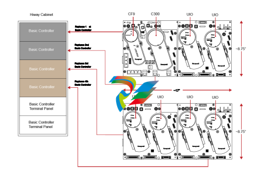
ATTENTION
Note that you can increase the number of input/outputs by adding the Universal
Input/Output (UIO) modules.
2.6.2 Features of UHIO
The key features of the UHIO are:
l Supports both redundant and non-redundant configuration for C300 Controller, UIO module,
and CF9.
l Supports interchangeability of Series C components.
l Minimizes the effort for rewiring.
The UHIO also supports the following features.
l Provides mechanical connection to the TDC 2000 cabinet Backplane.
l Supports cabinet ground connections through the IOTA mounting screws.
l Provides electrical-mechanical connection to the IOM.
l Provides electrical-mechanical connection to the redundant IOL cable pair.
l Supports 24V fused electrical connections to the IOM(s) - Series C 24V and COM power supply.
l Supports a signal common ground.
l Supports precision resistors for measuring analog inputs
ATTENTION Note that you can increase the number of input/outputs by adding the Universal Input/Output (UIO) modules. 2.6.2 Features of UHIO The key features of the UHIO are: l Supports both redundant and non-redundant configuration for C300 Controller, UIO module, and CF9. l Supports interchangeability of Series C components. l Minimizes the effort for rewiring. The UHIO also supports the following features. l Provides mechanical connection to the TDC 2000 cabinet Backplane. l Supports cabinet ground connections through the IOTA mounting screws. l Provides electrical-mechanical connection to the IOM. l Provides electrical-mechanical connection to the redundant IOL cable pair. l Supports 24V fused electrical connections to the IOM(s) - Series C 24V and COM power supply. l Supports a signal common ground. l Supports precision resistors for measuring analog inputs
l Supports connection for up to 24 IO channels on the existing TCBs.
l Supports connection for up to 8 additional IO channels at a location.
l Supports manual reset input(s) for restarting a stopped UIO module.
l Supports voltage or current inputs.
l Supports hot-insertion of C300, CF9, and UIO modules.
2.6.3 UHIO hardware
The UHIO uses the following Series C IO components.
l Plug-in modules such as C300, CF9, and UIO.
l FTE network communications between the controller and Experion Station.
l I/O Link between the controller and all I/O modules.
l Series C cabinet power supply.
l Experion Station and Control Builder as operator and engineering interfaces.
ATTENTION
You cannot differentiate the appearance of the UHIO components from other Series C
components in the Control Builder or the Station though the UHIO components are
horizontally-oriented.
2.6.4 Differences between the Series C IOTA and the UHIO IOTA
The following table lists the differences between the Series C IOTA and the UHIO IOTA.
Series C IOTA UHIO IOTA
C300, CF9, and the UIO IOTA is mounted on
the Series C cabinet.
New IOTA developed for C300/CF9 IOTA and UHIO
cannot be mounted on the Series C CCA’s. It can be
mounted in a TDC 2000 basic cabinet (not a Series C
cabinet) or in a PMIO cabinet using a special
mounting bracket.
Series C UIO IOTA does not interface UIO
module to Basic Controller Terminal Panels
(TCBxx). Instead, Series C UIO IOTA is
designed to directly interface with the field
sensors/actuators.
UHIO IOTA is designed to interface the UIO module
to the Basic Controller Terminal Panels (TCBxx).
Series C IOTA is vertically mounted on the
cabinet.
UHIO IOTA is horizontally mounted on the cabinet.
Table 2.2 Differences between the Series C IOTA and the UHIO IOTA
ATTENTION
Series C Hazardous Certifications are not applicable to the UHIO components.
For more information about the C300/CF9/UHIO IOTA, see Series C Universal Horizontal
Input/Output (UHIO) components.
About UHIO certification
General Purpose Certification
The UHIO’s CSA General Purpose certification is applicable within Data Hiway (TDC 2000) cabinets
with the Series C Power supply SPS5792-142935 (HPN 51454517-100). If any modifications have
occurred since first installation, the UHIO’s CSA General Purpose certification is voided and it is
the responsibility of the end user to ensure they are still conforming to all applicable agency rules
and regulations. The original TDC Basic Power Supplies do not support the UHIO CSA General
Purpose Certification.
CE Mark certification
The UHIO's CE Mark is only applicable for installations within Data Hiway (TDC 2000) cabinets with
the Series C Power supply SPS5792-142935 (HPN 51454517-100). It is assumed that the state of
as shipped and as first installed has been maintained for all applicable installations. For
installations that do not satisfy the previously mentioned conditions, the end user is responsible to
ensure that they conform to all applicable agency rules and regulations.
CC-HUIO12
The above constraints also apply to the CC-HUIO12 IOTA. Note that the CC-HUIO12 was tested
with TCB cable 51192054 only. Using the original TCB cable 30731611 with adaptor cable 51202979
may not pass CE Mark tests. For the conducted immunity test between 150kHZ and 250kHz, the AI
accuracy was 4.3% instead of its normal 0.1% at room temperature.
SERIES C I/O PLANNING AND DESIGN
This guide is intended to provide general information to assist you in planning and designing the
installation of your Experion Series C I/O.
l General Planning References
l Series C I/O and C300 topology
l Supported Series C I/O modules
l Supported Series C I/O options
l I/O Link performance specifications
l Universal Input/Output Module-2 (UIO-2)
3.1 General Planning References
Refer to the following documents for planning and design details for the Experion system in
general and the Fault Tolerant Ethernet supervisory network. For the sake of brevity, this Guide
does not repeat the applicable general guidelines, considerations, and cautions that are covered
in these other Guides.
l Control Hardware Planning Guide
l Server and Client Planning Guide
l Fault Tolerant Ethernet Overview and Implementation Guide
TIP
For complete Series C Control System Hardware Configuration planning information, refer
to the Control Hardware Planning Guide.
l Series C I/O appearance
l Series C I/O features
3.1.1 Series C I/O appearance
The layout of Series C components supports enhanced heat management and provides a 30%
reduction in overall size (space required to mount the hardware) versus the equivalent Process
Manger set.
3.1.2 Series C I/O features
The features of Series C I/O include:
l IO Module design - tilted 18 degrees off center:
o provides for better heat distribution
o allows for efficient field wiring
l Combination of I/O Module and Field terminations in the same area. The I/O Module is
mounted on the IOTA, which reduces cabinet space and eliminates items such as FTA
connection cables.
l Redundancy is done directly on the IOTA by simply adding a second IOM to the IOTA (with the
exception of the C300 controller).
For complete feature/functions for the following modules/IOTAs, refer to the Experion Series C
I/O Specifications document.
I/O
module/IOTA
Feature/function
Analog Input
w/HART
l Extensive self-diagnostics
l Optional redundancy
l HART capable, multi-variable instruments
l Fast (50ms) loop scan
l PV protection through a broken-wire detection diagnostic
l All channels configured for 4-20 mA inputs can detect broken
field wires. A soft failure alerts the maintenance staff for
corrective action.
l Non-incendive field power
l Non-incendive power for 4-20 mA loops is provided with no
external marshalling.
Analog Input
non-HART
l Extensive self-diagnostics
l Optional redundancy
l Fast (50ms) loop scan
l Non-incendive field power
Analog Output
w/HART
l Extensive self-diagnostics
l Optional redundancy
l HART capable, multivariable instruments
l Safe-state (FAILOPT) behaviors
l Each channel can be configured to HOLD, LAST, VALUE, or
SHED to a SAFE VALUE.
l Output read back checking of current delivered to the field
l PV protection through a broken-wire detection diagnostic
l Each channel can detect broken field wire. A soft failure alerts
the maintenance staff for corrective action.
l Non-incendive output
l No external marshalling required to support the 4-20ma loop,
and still provides for channel power protection.
Analog Output
non-HART
l Extensive self-diagnostics
l Optional redundancy
I/O
module/IOTA
Feature/function
l Safe-state (FAILOPT) behaviors
l Each channel can be configured to HOLD, LAST, VALUE, or
SHED to a SAFE VALUE.
l Output read back checking of current delivered to the field
l Non-incendive output
Digital Input
24VDC
l Extensive self-diagnostics
l IOM redundancy
l Input direct/reverse
l Internal or external field power selections
l Galvanic isolation
l PV protection through a broken-wire detection diagnostic
l Each channel can detect broken field wire. A soft failure alerts
the maintenance staff for corrective action.
l Non-incendive output
l No external marshalling required to support the 4-20ma loop,
and still provides for channel power protection.
Direct Input
High Voltage
l Extensive self-diagnostics
l Optional redundancy
l Input direct/reverse
l Galvanic isolation
Digital Input
High Voltage
PROX
l Extensive self-diagnostics
l Input direct/reverse
l Galvanic isolation
Direct Input -
Sequence of
Events
DI-SOE
l Extensive self-diagnostics
l Optional redundancy
l 1ms Sequence of Events for Discrete Inputs
l Low Latency / High Speed Scanning mode
l Broken wire detection
l Supplies non-incendive field power
l On board excitation power (no need for marshalling power)
l Direct / Reverse Input Indication
Galvanic isolation
Direct Output
bussed 24Vdc
l Extensive self-diagnostics
l Functional redundancy
l Output direct/reverse
l Safe-state (FAILOPT) behaviors
l Each channel can be configured to HOLD, LAST, VALUE, or
SHED to a SAFE VALUE.
l Fuse-less short circuit protection
allows a short circuit to exist without blowing any fuses. When a particular
channel is shorted, internal circuits detect this and remove power to the
I/O
module/IOTA
Feature/function
field connection. The channel remains de-energized until the short circuit
is repaired
l Latched, pulsed or pulse-width modulated output
l Galvanic isolation
l Output read back checking to screw terminal
Digital Output -
Relay IOTA
l Galvanic isolation
l Counter EMF snubbing circuit
l Isolated dry contact (Form A or B)
l Output read back checking on system side of driver
Low Level
Analog
(temperature)
Input - LLMUX
l TC and RTD operation
l Remote cold junction capability
l 1 Second PV scanning with OTD protection
l Configurable OTD protection (See below)
l Temperature points can be added in 16 point increments
Low Level
Analog
(temperature)
Input - LLAI
l Thermocouple (TC) and RTD operation
l 1 Second PV scanning with Open Thermocouple Detection (OTD)
protection
l Configurable OTD protection
Speed
Protection
Module - SP
l Supports 2/3 voting logic for speed and acceleration.
l Supports multiple configurable trip limits for speed and acceleration.
Servo Valve
Positioner
Module - SVPM
l Supports PID execution and position calibration.
l Computes valve position from LVDT/RVDT input signal and controls valve
by signaling the Servo coil.
l Provides current modulation to avoid stiction in controlled device (servo
valve).
Pulse Input
Module - PIM
l Highly accurate frequency/period calculations.
l Supports Dual Pulse Integrity in accordance with ISO6551:1996 Level A for
custody transfer applications.
l Extensive self-diagnostics.
l Functional redundancy.
l Provides channel-to-channel and terminal block to backplane voltage
isolation.
Universal
Input/Output
Module - UIOM
l Extensive self-diagnostics
l Optional redundancy
l Independently configurable I/O channels
l controls DI, AI, DO, AO
l HART capable, multivariable instruments
l PV protection through a broken-wire detection diagnostic
l Safe-state (FAILOPT) behaviors
l Supports multiple channel configurations
UIO-2
I/O
module/IOTA
Feature/function
In addition to all features supported by UIO, the UIO-2 supports the folowing
additional features:
l Provides one HART modem per I/O channel
l Supports pulse counting on up to four of any of the 32 channels
configured as DI
l Supports DO ganging within the following eight channel number groups: 1
- 4, 5 - 8, 9 - 12, 13 - 16, 17 - 20, 21 - 24, 25 - 28, and 29 – 32. However,
ganging across these groups is NOT possible
Beginning with ExperionR501, the following new features are available:
l Supports SOE on any channel
l Supports NAMUR inputs. This function, however, will require external
voltag
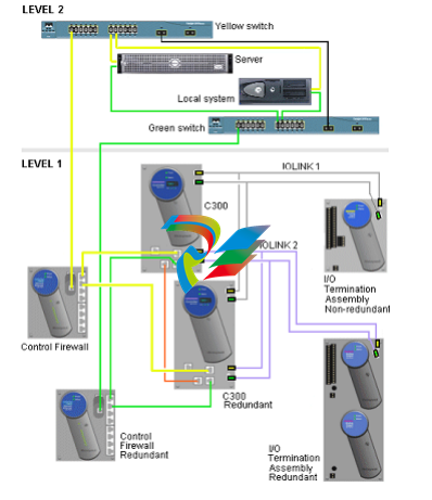
Series C I/O and C300/CN100 topology
ATTENTION
Topology for the Series C I/O and C300 - 20mS CEE Controller is similar to the Series C I/O
and C300 - 50ms Controller, with the exception that the C300 - 20mS CEE Controller does
not support the PMI/Os. CN100 supports all the Series C family of I/Os with the exception of
SPM and SVPM.
Series C I/O is attached to an IOLINK that is being mastered by a C300 controller. It is important to
note that:
l IOLINK - Serves as data repository for IOM function blocks in Control Builder to provide
communications interface with Series C I/O.
l Series C I/O cannot reside on an IOLINK mastered by an IOLIM or xPM.
Examining the topology rules
The following are the topology rules relating to the Series CI/O environment.
Refer to the following document for graphical representations of cabinet layouts depicting Series
C, PMIO, FIM, and LLMUX hardware configurations. Control Hardware Planning Guide
Item Impact Description
Redundancy None Redundancy capacity and performance is displayed while
redundancy is present.
Switchover Same as PM
I/O
Series C I/O hardware and/or software can switchover, recover,
and resume full view in a timeframe no greater than PM I/O.
Initialization All Series C I/O
per
C300/CN100
Can be initialized in 60 seconds (+/- 25%) after cabinet-level loss
power loss.
I/O module Can be initialized in 10 seconds (+/- 25%) after IOM level loss
power loss.
Multiple I/O
Links
2 Design allows the use of multiple Series C I/O Links in the same
cabinet.
tem Impact Description
I/O Link
performance
None I/O Link networks perform at the current distance and IOP count
specifications.
I/O Link
capacity
40 max Maximum of 40 redundant IOMs per link
(for either Series C I/O or PM I/O).
IOMs / C300 64 max Maximum of 64 redundant IOMs per C300 (for PM I/O).
80 max Maximum of 80 redundant IOMs per C300 (for Series C I/O).
Series C and
PM I/O -
combined
64 Design supports Series C and PM I/O FTAs in the same side of the
cabinet. Current configuration prevents IOTA and FTAs in the
same column.
I/OMs/CN100 40 Max Maximum of 40 redundant I/OMs per CN100
3.3 Supported Series C I/O modules
The list of I/O modules below can be used on a Series C IOLINK. The IOLINK contains a function
that enables programming and reprogramming the executable image (rather than substitution of
a removable hardware component). The preferred method of delivery of the image is over the
IOLINK.
Refer to Life Cycle changes for Series C IO modules and IOTAs section for life cycle update.
TIP
Series C IOLINK cannot contain any PM I/O IOPs.
C300 IOLINK block parameter IOLINKTYPE is used to determine if the IOLINK supports
either Series C I/O or PM I/O.
IOM
model
names
IOM block
name
Description # of
chnls
Similar to
PMIO type
IOP
model
names
CUPAIH01
CCPAIH01
AI-HART High Level Analog Input with HART
(supports differential inputs on only
channel 13 through channel 16)
Refer to Attention
16 HLAIHART
CCPAIH02
AI-HART2 High Level Analog Input with HART
((supports differential inputs on all 16
channel)
16 HLAIHART
CCPAIX02
AI-HART2 High Level Analog Input with
Differential/Single-ended non-HART
(supports differential inputs on all 16
channels)
16 HLAI
CCPAIX01
AI-HL1 High Level Analog Input with Differential
non-HART
(supports differential inputs on only
channel 13 through channel 16)
16 HLAI
NOTES:
1. There are two models of High Level Analog Input such as, CU-PAIX01 and CU-PAIN01. The
Module Hardware and the corresponding IOTAs are different and CU-PAIN01 is a new model.
From the perspective of configuration and implementation, both High Level Analog Input
models use the same IOM Block such as, AI-HL. It must be noted that the two models utilize
the same configuration; online migration is not possible as mixed redundant pair is not
possible. There are two models of Analog Output such as, CU-PAOX01 and CU-PAON01.
Hence, similarly configuration, implementation, and interoperability constraints apply and CUPAON01 is the new model.
2. Two new models of AI-HART (CC-PAIH02) and AI-HL (CC-PAIX02) modules are introduced to
replace the older models of the AI-HART (CC-PAIH01) and AI-HL (CC-PAIX01) modules. The
new models support both single-ended and differential inputs.
3. With R410, a new model of HART Analog Input CC-PAIH51 is introduced. The HART Analog
nput CC-PAIH51 and Cx-PAIH01 use the same IOM block, that is, AI-HART. The configuration
and implementation mentioned in note 1 applies to the HART Analog Input module.
4. With R410, a new model of HART Analog Output CC-PAOH51 is introduced. The HART Analog
Output CC-PAOH51 and Cx-PAOH01 use the same IOM block, that is., AO-HART. The
configuration and implementation mentioned in note 1 applies to the HART Analog Output
module.
5. With R410, a new model of Digital Input 24V DC CC-PDIL51 is introduced. The Digital Input
24V DC CC-PDIL51 and Cx-PDIL01 use the same IOM block, that is, DI-24. The configuration
and implementation mentioned in note 1 applies to the Digital Input 24V module.
6. With R410, a new model of Digital Output 24V DC CC-PDOD51 is introduced. The Digital
Output 24V DC CC-PDOD51 and Cx-PDOB01 use the same IOM block, that is, DO-24B. . The
configuration and implementation mentioned in note 1 applies to the Digital Output 24V
module.
7. Starting with R430, a new model of Low Level Analog Input Mux CC-PAIM51 is introduced.
8. The UIO (CC-PUIO01) has 32 configurable input or output channels. Each channel can be
configured as one of the following:
l Analog Input (0-20mA or 4-20mA active)
l Analog Output (4-20mA active)
l Digital Input (with or without line monitoring)
l Digital Output (with or without line monitoring)
9. The UIO (CC-PUIO31) module is introduced with R432 and has 32 configurable input or output
channels that are identical to the UIO (CC-PUIO01) module.
ATTENTION
Series C IO modules introduced in ExperionPKS R410.x release should not be used
with its prior ExperionPKS releases R400.x. Do not try to downgrade the firmware of
Series C IO Modules introduced in ExperionPKS R410.x release, as IOM will not
work and it is difficult to recover as well.
l Compatibility matrix between AI modules and differential AI modules
l Compatibility matrix between AO modules and differential AO modules
l Difference between AI-HART modules Cx-PAIH01 and Cx-PAIH51
l Difference between AO-HART modules Cx-PAOH01 and Cx-PAOH51
l Difference between bussed low voltage Digital Input modules Cx-PDIL01 and Cx-PDIL51
l Difference between low voltage Digital Output modules Cx-PDOB01 and Cx-PDOD51
l Difference between AI-LLMUX and CC-PAIL51 modules Cx-PAIM01 and Cx-PAIM51
l Identifying supported Series C I/O modules
l Considerations for replacing or pairing Series C Analog I/O modules in a redundant
configuration
3.3.1 Compatibility matrix between AI modules and differential AI
modules
You can choose the AI modules based on your functionality requirements. The following table lists
the functionalities and the respective AI modules.
-
 HIRSCHMANN MSM20-M2M2M2M2SY9HH9E Ethernet media modul
 -
 HIRSCHMANN SPIDER-PL-20-05T1999999TWVHHHH Industrial Ethernet Rail Switch
 -
 Hirschmann SPIDER-PL-20-07T1M2M299TWVHHHH Industrial ETHERNET Rail Switch
 -
.png) Hirschmann (Belden) RS20-1600M2M2SDAEHC09.1.00 DIN-rail managed industrial Fast Ethernet switch
Hirschmann (Belden) RS20-1600M2M2SDAEHC09.1.00 DIN-rail managed industrial Fast Ethernet switch -
 Hirschmann (Belden) RS30-1602O6O6TDAPHC09.1.00 DIN-rail managed industrial Ethernet switch
 -
 Hirschmann (Belden) RS30-2402O6T1SDAPHH09.0.13 DIN-rail industrial Ethernet switch
 -
Hirschmann (Belden) SPIDER-PL-20-04T1S29999TY9HHHH Ethernet DIN-rail switch
-
 HIRSCHMANN RS20-1600T1T1SDAUHX Switch
 -
 HIRSCHMANN BRS42-0012OOOO-SPCZ99HHSES industrial switch
 -
 Hirschmann RS20-0800S2S2TDHPHH09.0.14 Fast Ethernet DIN rail switch.
 -
 HIRSCHMANN MM20-Z6Z6M2M2SAHH Hybrid Fast Ethernet Media Module
 -
 HIRSCHMANN MM20-Z6Z6T1T1SAHH hot-swappable hybrid Fast Ethernet Media Module
 -
 HIRSCHMANN MM20-P9P9T1T1SAHH Hybrid Fast Ethernet Media Module
 -
 HIRSCHMANN MM20-M4T1T1T1SAHH Hybrid Fast Ethernet Media Module
 -
 HIRSCHMANN MM20-M4M4T1T1SAHH Hybrid Fast Ethernet Media Module
 -
 HIRSCHMANN MM20-M2M2M2M2SZHH Ethernet media module
 -
HIRSCHMANN MM20-M2M2M2M2SAHH Ethernet media module
-
 HIRSCHMANN MM20-T1T1T1T1EBH 4-port Fast Ethernet Copper Cable Media Module
 -
HIRSCHMANN MM20-T1T1T1T1SAHH 4-port Fast Ethernet Copper Cable Media Module
-
HIRSCHMANN MM20-T1T1T1T1SAHH 4-port Fast Ethernet Copper Cable Media Module
-
 HIRSCHMANN MM20-Z6Z6EBH Hot-swappable fast Ethernet media module
 -
 HIRSCHMANN MM20-Z6Z6SAHH Ethernet media module
 -
HIRSCHMANN MM20-Z6Z6Z6Z6EBH Industrial Media Module
-
 MSM40-T1T1T1TZ9HH9E99.9.99 HIRSCHMANN Switch
 -
 HIRSCHMANN MS20-0800SAAEHC / MS20-0800SAAEHC0 8-port modular Layer 2 management Ethernet switch
 -
 Hirschmann RSPM20-4T14T1SZ9HHS9 Switch RSPM20-4T14T1SZ9HHS9
 -
 HIRSCHMANN RS20-1600M2M2SDAEHH09.1. RS20/30/40 Managed Switch configurator
 -
HIRSCHMANN RS20-1600M2M2SDAEHX09.0.00 Ethernet switch
-
 HIRSCHMANN BELDEN SPIDER-PL-20-07T1M2M299TY9HHHH / SPIDERPL2007T1M2M299TY9HHHH
 -
HIRSCHMANN MM3-1FXS2/3TX1 Switching Board Module
-
 HIRSCHMANN RSPE30-24044O7T99-ECCP999HHSE2A08.1.00 Industrial-grade fanless management-type Ethernet switch
 -
 HIRSCHMANN RS30-1602OOZZSDAEHC09.1.00 DIN-rail-mounted managed Layer 2 Ethernet switch
 -
 HIRSCHMANN MACH104-20TX-F Managed 24-port Full Gigabit 19" Switch
 -
 HIRSCHMANN Switch RS20-0800M4M4SDAE
 -
Hirschmann RS30-1602O6O6SDAEHH09.1. Management-type Ethernet switch
-
 Hirschmann RS30-1602OOZZSDAEHC09.0.10 Open rack-style Ethernet switch
 -
 HIRSCHMANN RSPE30-24044O7T99-SCCV999HHSI2SXX.X.XX High-Availability Seamless Redundancy
 -
HIRSCHMANN RSPE30-24044O7T99-SCCZ999HHSE2A DIN-rail Ethernet switch
-
HIRSCHMANN MM2-4TX1-EEC switch
-
HIRSCHMANN MSM40-T1T1T1T1TZ9HH9E99.9.99 Module
-
 HIRSCHMANN RS20 Rail Switch RS20-0400S4T1SDAEHC07.1.01
 -
 HIRSCHMANN M4-FAST8-SFP Fast Ethernet media module
 -
 HIRSCHMANN RS20-0400M2T1SDAP Managed Fast-Ethernet-Switch
 -
 HIRSCHMANN BELDEN SPIDER II 8TX/1FX EEC Industrial Ethernet Rail Switch
 -
HIRSCHMANN MM3-2FXS2/2TX1
-
 HIRSCHMANN RS2-4TX/1FX EEC Industrial Ethernet Rail Switch
 -
 RS30-0802O6O6SDAEHC09.0.10 HIRSCHMANN Switch
 -
 HIRSCHMANN m4-8TP-RJ45 Ethernet Media Module
 -
 HIRSCHMANN MSP30-24040SCZ9URHHE3A switch
 -
 Hirschmann rack MS30-1602SAAPHC
 -
 HIRSCHMANN RS2-FX/FX Industrial Switch Module
 -
Rs1txfx - Hirschmann - Rs1-Tx/Fx Rail Switch
-
RS20-0800S2S2SDAEHC09.1.00 HIRSCHMANN Commutator
-
 Hirschmann EAGLE20 TX/TX Industrial Security Router
 -
 Hirschmann SPIDER-SL-20-04T1S29999SY9HHHH Industrial Switch
 -
 HIRSCHMANN MAR1040-4C4C4C4C9999SMMHRHHXX.X. Gigabit Ethernet Switch configurator
 -
 Hirschmann MAR1040 Industrial Switch
 -
 HIRSCHMANN BELDEN RS30-1602O6O6SDAE
 -
Hirschmann RS20-1600M2M2SDAUHC Ethernet DIN rail switch
-
 HIRSCHMANN OCTOPUS 24M industrial switch
 -
 HIRSCHMANN RS20-1600T1T1SDAE Management-type Ethernet switch
 -
 HIRSCHMANN RS20-1600T1T1SDAUHH industrial switch
 -
HIRSCHMANN RS20-0800M2M2SDAPHC09.0.04 switch
-
 Hirschmann MR 8-03 24V DC Industrial Modular Bridge/Router
 -
 HIRSCHMANN RS20-0400M2T1SDAPHC08.0.01 Managed Switch
 -
 MACH1130 Hirschmann Industrial Switch
 -
 HIRSCHMANN 943824-002 SPIDER 5TX Industrial Ethernet Switch
 -
 HIRSCHMANN RS30-0802O6O6SDAEHC09.1.00 Managed Industrial Switch
 -
 HIRSCHMANN RS20-0400M2M2TDAEHC04.0.01 Industrial Switch
 -
 HIRSCHMANN BRS20-0600Z6Z6-STCZ99HHSES Industrial Switch
 -
 HIRSCHMANN MACH104-20TX-FR-L3P Industrial Ethernet Switch
 -
 HIRSCHMANN RS40-0009CCCCEDBPHH06.0.01 Industrial Switch
 -
 HIRSCHMANN RS2-3TX/2FX EEC Industrial Ethernet Switch
 -
 Hirschmann MACH 1020/1030 Fast/Gigabit Rack Mount Switches
 -
HIRSCHMANN RS20-0800M2M2SDAPHC09.0.14 Industrial Switch
-
 HIRSCHMANN RS20-1600T1T1SDAEHC09.0.04 Industrial Switch
 -
 HIRSCHMANN RSB20-0800T1T1EAABHH Industrial Switch
 -
 HIRSCHMANN MACH4002-48+4G-L3E Industrial Backbone Switch
 -
 HIRSCHMANN RS20-0400S2T1SDAE Industrial Managed Switch
 -
HIRSCHMANN RS20-0800S2T1SDAUHC Industrial Switch
-
 HIRSCHMANN RS20-2400S4S4SDAEHC09.0.14 industrial switch
 -
 HIRSCHMANN OS20-001200T5T5T5- TBBZ999HHNE3S 08.1.00 industrial switch
 -
HIRSCHMANN OS20-001200T5T5T5- TBBZ999HHNE3S 08.1.00 industrial switch
-
 HIRSCHMANN RS40-0009CCCCSDAEHH09.0.14 switch
 -
 Hirschmann RS20-1600T1T1SDAUHC Management-type Ethernet Switch
 -
 Hirschmann M1-8SFP Switche
 -
Hirschmann Industrial Ethernet Ruggedized Switch MACH1000 Family
-
 Basler Electric, Solid State Protective Relay, BE1-60
 -
BASLER ELECTRIC SR4A-2B15B3A Static Voltage Regulator
-
.png) BASLER ELECTRIC EXCITER DIODE MONITOR EDM-200
BASLER ELECTRIC EXCITER DIODE MONITOR EDM-200 -
.png) BASLER ELECTRIC DECS125-15-B2C5 DIGITAL EXCITATION CONTROL SYSTEM V 2.0.9
BASLER ELECTRIC DECS125-15-B2C5 DIGITAL EXCITATION CONTROL SYSTEM V 2.0.9 -
 BASLER ELECTRIC BE1-851 OVERCURRENT PROTECTION RELAY MECHANISM
 -
 Basler Electric BE1-51A / BE151A
 -
 Basler Electric BE1-40Q Loss of Excitation Relay
 -
 Basler Electric BE1-87G Variable Percentage Differential Relay
 -
 Basler Electric BE1-11 Protection System I5A3M2P2N0EA00
 -
 BASLER ELECTRIC DECS-200-1C Digital Excitation Control System
 -
 Basler Electric / Kohler BE1-11g Generator Protection Relay G5A3M2J2N0E000
 -
BASLER ELECTRIC DECS125-15 DIGITAL EXCITATION CONTROL SYSTEM
-
 BASLER ELECTRIC BE1-951 OverCurrent Protecton System
 -
Basler Electric DECS-200-1L Digital Excitation Control System
-
 Basler Electric DGC-2020HD-5NS1DNSBA Digital Genset Controller -
 -
 BASLER ELECTRIC BE1-81T1EE1WA0N1F / BE181T1EE1WA0N1F
 -
 BASLER ELECTRIC BE1-25M1EA6PN5R1F / BE125M1EA6PN5R1F
 -
 BASLER ELECTRIC DECS-250-LN1SN1N DIGITAL EXCITATION CONTROL SYSTEM
 -
Basler Electric DECS-250-CN2CN 1N Digital Excitation Control System Unit
-
 BASLER ELECTRIC DECS-300-C0N0 DIGITAL EXCITATION CONTROL SYSTEM
 -
 BASLER ELECTRIC BE1-87T-A1E-A1J-D0S1F / BE187TA1EA1JD0S1F
 -
BASLER ELECTRIC BE1-11-G6D1M0J2P0E000 Protection System
-
 BASLER ELECTRIC BE1-GPS100-E4N1H1N GENERATOR PROTECTION SYSTEM
 -
 Jaquet Relay card (Auxiliary module) FTV 3090 377Z-03985
 -
 Jaquet Trip Chain Control card FTBU 3034 377Z-05030
 -
 Jaquet with input card -E04 FTFU 3024 -E04 377Z-05855
 -
 Jaquet with input card -E03 FTFU 3024- E03 377Z-03983
 -
 Jaquet FTFU 3024- E02 377Z-03982 with input card -E02
 -
 Jaquet FTFU 3024-E01 377Z-03981 with input card -E01
 -
 Hirschmann RS20-2400T1T1SDAE Industrial Managed Ethernet Switch
 -
 Hirschmann BELDEN EAGLE30-04022O6TT999SCCV9HSE3F
 -
 Hirschmann MM3-2FXS2/2TX MICE Media Module
 -
 Hirschmann RS20-1600M2M2SDAPHC08.0.05 Industrial Managed Switch
 -
 Hirschmann OZD Profi 12M G12-1300 PRO Fieldbus Repeater
 -
Hirschmann SPIDER 4TX/1FX-ST EEC Industrial Ethernet Switch
-
 Hirschmann MM2-2FXM3/2TX1 MICE Media Module
 -
 Hirschmann RS20-2400M2M2SDAPHC09.0.14 Industrial Switch
 -
 Hirschmann RS20-0400M2M2SDAEHC07.1.05 OpenRail Switch
 -
 Hirschmann OZD Profi 12M G12-EEC Fieldbus Repeater
 -
HIRSCHMANN MDA422-1/2-3.5c-23/46 sensor
-
Hirschmann RS30-2402T1T1SDAUHC Managed Industrial Switch


