
Electro-Pneumatic Positioner TZIDC, TZIDC-1x0, TZIDC-2x0
Selecting a parameter within a group
1. Press and hold MODE . The display indicates the reference number (top) and the designator (bottom) of the current parameter. 2. Additionally, press or until the reference number and the designator of the desired parameter are displayed. 3. Release all buttons. The display indicates the value of the selected parameter (top). At the bottom the designator is still shown. For parameters that can assume different states (e.g., ACTIVE or INACTIVE) the reference number is displayed at the top and the state at the bottom. The value/state of the parameter can be changed.
Changing a parameter
1. Press or until the desired value or state is shown.
Important
When keeping the respective direction button pressed, parameters with values are changed dynamically. The change rate is increased every second until the limit value of the parameter is reached.
Saving data and exiting the configuration level 1. Select the EXIT parameter for the respective parameter group and set it to one of the two possible states using or : NV_SAVE Activates your changes and saves them in the non-volatile memory. The positioner returns to the operating level. CANCEL Changes are discarded. The positioner returns to the operating leve
Important
The parameters are only saved in the non-volatile memory by leaving the configuration level via EXIT -> SAVE. Multiple parameters in different groups can also be changed sequentially. When leaving the last parameter group via EXIT -> SAVE, all previously made modifications are saved and applied
2. Press and hold ENTER until the displayed countdown from 3 to 0 is complete.
3. Release the ENTER button. The positioner returns to the operating level. The configuration level was accessed from this mode. Depending on the selection the data is saved in the non-volatile memory or discarded. During the save operation a plausibility check is performed. If an error occurs during the check or while data is being saved, an error message is displayed (see the chapter titled "Error messages").
Starting an action
1. Press and hold ENTER until the displayed countdown from 3 to 0 is complete.
2. Release the ENTER button. The selected action is started.
Important
If you release ENTER before the countdown is complete, the action will not be started.
To acknowledge a message
During the course of some actions (e.g., Autoadjust) messages are displayed that have to be acknowledged. Messages that must be acknowledged are identified by the value display (top line) being empty (see adjacent example).
Acknowledgement
1. Briefly press ENTER. The positioner continues with the action and/or finishes the procedure correctly
To cancel an action 1. Briefly press ENTER . The positioner aborts the action in progress (e.g., Autoadjust).
Operation on the operating level
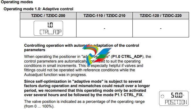
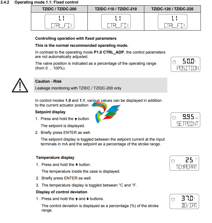
On the operating level, the positioner works in the selected operating mode. There are four operating modes:
• 1.0 CTRL_ADP (adaptive control)
• 1.1 CRTL_FIX (fixed control)
• 1.2 MANUAL (manual adjustment within the stroke range)
• 1.3 MAN_SENS (manual operation within the sensor range)
For details regarding switching between the modes, refer to the section titled "Functions on the operating level". When the 4 ... 20 mA signal is fed in, the positioner automatically starts up in the mode that was last active. Devices from the factory start up in operating mode 1.3. This also applies to devices that have been reset to the factory setting. In both manual modes, the valve can be adjusted manually by pressing or . The two automatic control modes are indicated by the control loop symbol in the display. For the manual modes the hand symbol is shown in the display.
Inhibiting operation
Positioner operation can be inhibited completely or partially via the digital input and the FUNCTION parameter in parameter group 10 (DIG_IN (digital input)). This allows the user to prevent or restrict operating actions of unauthorized personnel as desired. When operation is disabled in this way, the key symbol is indicated in the display. The following levels of configuration locks are possible: Inhibiting the local configuration Local operation on the operating level and remote operation and configuration via a PC are still possible. Inhibiting all local operating functions No local operating actions can be executed. Both the operating level and the configuration level are locked. Remote operation and setting of parameters via a PC is still possible. Inhibiting local operation and remote configuration It is not possible to operate or configure the positioner locally or configure it using a PC.
Important
This inhibit function can only be deactivated when a voltage of 12 ... 24 V is applied at the digital input of the positioner (see Function selection in parameter group 10).
Parameter group 7: Control parameters

KP UP – KP value (up)

Important
All control parameters are determined in an optimum way for most actuators during Autoadjust. Changes should only be made when Autoadjust cannot be executed or control stability cannot be achieved. The KP value is the gain of the controller. The control speed and stability are influenced by the KP value. With higher KP values, the controlling speed increases.




.png)


.png)


.png)


