
johnsoncontrolsNAE55 Catalog Page
Introduction
The NAE55 is a specific series of network engine
that performs a key role in the Metasys system
architecture. Network engines provide network
management and system-wide control and
coordination over one or more Metasys equipment
controller networks, that include the following
series:
• CG series General Purpose Application Equipment
Controllers
• CV series VAV Box Controllers
• FAC and FEC series Field Equipment Controllers
• VMA series VAV Box Controllers
• TEC series Terminal Equipment Controllers
• LN series Equipment Controllers
• Legacy Metasys controllers, such as Unitary
(UNT) controllers, Variable Air Volume Assembly
(VMA14xx) controllers, and DX-9100 controllers
• Third-party equipment controllers
Note: The following IP controllers at
firmware 10.0 support BACnet™/IP and
BACnet/SC at Release 12.0.
- M4-CGE09090-0/-0H
- M4-CGE04060-0
- M4-CVE03050-0P
- MS-FAC4911-0
- MS-VMA1930-0
You can connect these network engines together
to scale up on large projects. For additional
functionality and site unification, you can network
the engines with an Application and Data Server
(ADS), an Extended Application and Data Server
(ADX), or an Open Application Server (OAS).
Use network engines for building control
scheduling, alarm and event management, energy
management, data exchange, historical data
storage and management, and custom control logic.
The NAE55 includes an embedded user interface
called the Site Management Portal (SMP). Users
access the SMP for system navigation and operation
with a web browser. To prevent unauthorized
access, network engines use password protection,
permission access, and IT security best practices.
Network engines provide network supervisor
capabilities, IP network connectivity, and third-party
device integration capabilities. NAE55s at Release
11.0 or later are FIPS 140-2 Level 1 compliant. The
Federal Information Processing Standard (FIPS)
140-2 is a United States government cybersecurity
standard that approves cryptographic modules/
algorithms used for encryption.
For information about the latest family of network
engines that are available at Release 10.1 or
later, refer to the SNE/SNC Product Bulletin
(LIT-12013296). For information about other
network engine models, refer to the NAE55 Catalog
Page (LIT-1900195). For information about network
engines that have approval for use at facilities that
require regulatory compliance, refer to the Metasys
for Validated Environments, Extended Architecture
Product Bulletin (LIT-12011326).
Application documentation
Refer to the Network Engines Product Bulletin
(LIT-12012138) for important product application
information.
Features and benefits
The following features and benefits are applicable to
all network engines, with specific features that vary
by model and software release.
Supervision of controller networks including
Johnson Controls and third-party protocol
devices
Support for connectivity to open network standards
for field device flexibility. Supported protocols are
model and software release dependent and include
BACnet/IP, BACnet Secure Connect (BACnet/SC),
BACnet MS/TP, LonWorks, N2 Bus, Modbus RTU,
Modbus TCP, M-Bus (EN 13757-3) serial and IP, KNX
IP, SIMPLEX® Fire, Zettler Fire Panel, Tyco C•CURE,
OPC Unified Architecture (UA), and other third-party
protocols.
Communication using commonly accepted IT
standards at the automation and enterprise level
The Metasys System installs on the IT infrastructure
in your building or enterprise and uses standard IT
communication services over the company Intranet,
WAN, public Internet with VPN tunnel, or firewall
protection. Network engines also support the ability
to optionally authenticate non-local users through
Syslog Destination Delivery Agent (DDA) for network
logging of Metasys audits and events.
FIPS compliance
Common to all network engines that run Release
11.0 or later firmware, the FIPS 140-2 feature
provides FIPS compliance to a customer's Building
Automation System (BAS). For a site to be fully FIPS
compliant, you need to upgrade all network engines
to Release 11.0 or later, then install and license the
FIPS 140-2 feature on the Metasys Server.
BACnet/SC
BACnet/SC is a recent update to the BACnet
interoperability standard to improve cybersecurity
and network infrastructure integrity. BACnet/
SC identifies a secure, encrypted datalink layer
designed to meet the requirements, policies, and
constraints of IP networking infrastructures.
Secure web-based user interface
Access system data in the network engines from
any device that is connected to the network with
a supported web browser. All upgraded network
engines have self-signed certificates for encrypted
communication. Optionally, you can deploy
trusted certificates to the network engines that the
customer's IT department or a Certificate Authority
(CA) provide and manage.
Site Director function
If you set up one network engine as a Site Director,
you can access all site data from that single device.
The device that is designated as the Site Director
coordinates the display of data from a maximum of
three engines for easy navigation through the entire
site. This capability is available to all network engine
models.
Embedded user interface and online system
configuration software
Use the password-protected software to enable,
configure, commission, archive data, monitor,
command, and perform system diagnosis from any
device through a web browser, without the need for
separate workstation software.
Linux® operating system
The NAE55 network engines at Release 10.0 and
later run on Linux, which is a robust, widelyaccepted, and readily-supported operating system.
Background file transfer
With this new feature, you can transfer firmware
upgrades, archive databases, HTTPS security
certificates, and security databases from the
System Configuration Tool (SCT) to the NAE55
while the engine remains operational, minimizing
system disruptions. Background file transfer is
only available for NAE55s at Release 10.1 or later,
and for the new family of SNE and SNC network
engines that were introduced at Release 10.1. For
information about the newest engines, refer to the
SNE/SNC Product Bulletin (LIT-12013296)
Ordering information
Contact the nearest Johnson Controls representative to order a network engine. The following tables list the
product code numbers and accessories for all available network engines based on model. If you receive an
NAE55 engine from the factory that is imaged with an older release, you can field-upgrade the engine to
Release 12.0 if the upgrade is supported. To order repair parts, add -702 or -703 in place of the last number
(for example, MS-NAE5521-703).
Table 1: NAE5510-2U ordering information (Release 8.1 only)
Product code number Release Description
MS-NAE55xx-x. Base
features of each NAE55
N/A NAE55 Network Automation Engines: Requires a 24 VAC power supply.
Each model includes two RS-232-C serial ports, two USB serial ports,
two RS-485 ports, one Ethernet port, and one MS-BAT1010-0 Data
Protection Battery. Supports a BACnet IP network.
MS-NAE5510-2U
Note: You cannot purchase a MSNAE5510-2U as it is
discontinued. However, you can still
upgrade an MSNAE5510-2U to the
Metasys UL 864
Release 8.1.
8.1 Supports two N2 Bus or two BACnet MS/TP, RS-485 trunks or one N2
Bus trunk and one BACnet MS/TP trunk. Supports a maximum of 100
devices on each N2 Bus or BACnet MS/TP trunk.
Note: This model is UL 864 10th Edition UUKL/ORD-C100-13
UUKLC Standard for Smoke Control Equipment for Release 8.1
only. Refer to the Metasys® System UL 864 10th Edition UUKL/
ORD-C100-13 UUKLC Smoke Control System Technical Bulletin
(LIT-12012487) for detailed specifications, requirements, and procedures for installing and operating UUKL 864 Listed Metasys
system devices. For example, in order to be UL/cUL compliant,
this model must be pre-installed and pre-wired in a standard or
custom panel built at the Johnson Controls Reynosa factory.
MS-NAE5510-3U 8.1 Supports two N2 Bus or two BACnet MS/TP (RS-485) trunks or one N2
Bus trunk and one BACnet MS/TP trunk. Supports a maximum of 100
devices on each N2 Bus or BACnet MS/TP trunk.
Note: This model is UL 864 10th Edition UUKL/ORD-C100-13
UUKLC Standard for Smoke Control Equipment for Release 8.1
only. Refer to the Metasys® System UL 864 10th Edition UUKL/
ORD-C100-13 UUKLC Smoke Control System Technical Bulletin
(LIT-12012487) for detailed specifications, requirements, and procedures for installing and operating UUKL 864 Listed Metasys
system devices. For example, in order to be UL/cUL compliant,
this model must be pre-installed and pre-wired in a standard or
custom panel built at the Johnson Controls Reynosa factory.
Table 2: NAE55-3 ordering information (Release 8.1 or 12.0)
Product code number Release Description
MS-NAE55xx-x, base
features of each NAE55
N/A NAE55 Network Automation Engines: Requires a 24 VAC power supply.
Each model includes two RS-232-C serial ports, two USB serial ports,
two RS-485 ports, one Ethernet port, and one MS-BAT1010-0 Data
Protection Battery. Supports a BACnet IP network.
MS-NAE5510-3 12.0 Supports two third-party trunks, Modbus RTU or TCP, M-Bus, or KNX,
and two N2 or two BACnet MS/TP (RS-485) trunks or one N2 trunk and
one BACnet MS/TP trunk. Supports up to 100 devices on each N2 or
BACnet MS/TP trunk. Supports a BACnet/IP or BACnet/SC network.
This model is a BACnet BTL-Listed controller at protocol revision 15
(PR15). Supports BACnet/SC at Release 12.0.
MS-NAE5510-3U 8.1 Supports two N2 Bus or two BACnet MS/TP (RS-485) trunks or one N2
Bus trunk and one BACnet MS/TP trunk.
Note: This model is UL 864 10th Edition UUKL/ORD-C100-13
UUKLC Standard for Smoke Control Equipment for Release 8.1
only. Refer to the Metasys® System UL 864 10th Edition UUKL/
ORD-C100-13 UUKLC Smoke Control System Technical Bulletin
(LIT-12012487) for detailed specifications, requirements, and procedures for the installation and operation of UUKL 864 Listed
Metasys system devices. For example, in order to be UL/cUL compliant, this model must be pre-installed and pre-wired in a standard or custom panel built at the Johnson Controls Reynosa factory.
MS-NAE5520-3 12.0 Supports a LonWorks trunk, two third-party trunks, Modbus RTU or
TCP, M-Bus, or KNX, or two N2 trunks/BACnet MS/TP (RS-485) trunks,
or one N2 trunk and one BACnet MS/TP trunk. Supports up to 255
devices on the LonWorks trunk. Supports up to 100 devices on each N2
or BACnet MS/TP trunk. Supports a BACnet/IP or BACnet/SC network.
This model is a BACnet BTL-Listed controller at protocol revision 15
(PR15).
Ordering information - accessories
Table 3: Network engines accessories ordering information
Product code number Description
MS-BAT1010-0 Replacement data protection battery for NAE55. Rechargeable gel cell battery:
12 V, 1.2 Ah, with a typical life of 3 to 5 years at 21°C or 70°F
TL-MAP1810-xx A pocket-sized web server that provides a wireless mobile user interface
to Metasys field controllers, thermostats, and smart rooftop units. Refer to
the Mobile Access Portal Gateway Catalog Page (LIT-1900869) to identify the
appropriate product for your region.
Note: The MAP Gateway serves as a replacement for the BTCVT, which is
no longer available but continues to be supported.
MS-EXPORT-0 License enabling Metasys Export Utility software for new installation. Software
may be obtained by electronic download from the Licensing Portal.
AS-XFR100-1 Power transformer, Class 2, 24 VAC, 92 VA maximum output, with enclosure
AS-XFR010-1 Power transformer, Class 2, 24 VAC, 92 VA maximum output, no enclosure
Table 4: Modbus accessories ordering information
Product code number Description
IU-9100-8401 (Europe) RS232-to-RS485 converter, 230 VAC
Order this accessory in AOMS from the European Distribution Center.
IU-9100-8404 (Europe) or
BM485-CIP (North America)
RS232-to-RS485 converter, 24 VAC
For the European market, order this accessory in AOMS from the European
Distribution Center. For the North American market, order this accessory from
duTec at http://www.interfaceconverter.com or 1-800-248-1632, specify vendor
#290904
Table 5: M-Bus accessories ordering information
Product code number Description
SIS-MBUSSCSL-1E M-Bus level converter for up to 6 unit loads, 24V AC/DC, RS-232 connection
SIS-MBUSSCLL-0E M-Bus level converter for up to 100 unit loads, 24V AC/DC, RS-232 connection
SIS-MBUSNCLL-1E M-Bus level converter for up to 100 unit loads; 24 VAC/VDC (IP connection)
SIS-MBUSRPLL-0E M-Bus repeater for up to 100 unit loads, 24V AC/DC
SIS-MBUSRPLH-0E M-Bus repeater for up to 100 unit loads; 230 VAC
INT-DX-KAB01 Optional connection cable SUB-D to RJ-12 for use with SIS-MBUSSCLL-0E
Note: You can order these accessories in AOMS from the European Distribution Center.
Table 6: KNX accessories ordering information
Product code number Description
GRIPIN01-S-KNX KNX IP interface module to connect KNX line through Ethernet to a network
engine
GRRIN01-KNX KNX IP router to connect KNX line through Ethernet to a network engine,
including line or area coupler functionality
Note: Order these accessories in AOMS from the European Distribution Center.
Note: When you use the GRIPIN01-S-KNX for NAE integration, use a non-secure mode. Set Metasys driver N=ROUTING MODE and in ETS set "Secure mode" to deactivated.
Technical specifications
Table 7: NAE5510-2U (UL 864, Smoke Control) technical specifications
Power requirement Dedicated nominal 24 VAC, Class 2 power supply for North America at 50/60
Hz, 20 VAC minimum to 30 VAC maximum
Power consumption 50 VA maximum
Ambient operating
conditions
0°C or 32°F to 50°C or 122°F; 10% to 90% RH, 30°C or 86°F maximum dew point
Ambient storage conditions -40°C or 104°F to 70°C or 158°F; 5% to 95% RH, 30°C or 86°F maximum dew
point
Data protection battery Supports data protection on power failure. Rechargeable gel cell battery: 12 V,
1.2 Ah, with a typical life of 3 to 5 years at 21°C or 70°F; Product Code Number:
MS-BAT1010-0
Clock battery Maintains real-time clock through a power failure. Onboard cell; typical life 10
years at 21°C or 70°F
Processor 1.6 GHz Intel Atom® processor
Table 7: NAE5510-2U (UL 864, Smoke Control) technical specifications
Memory 4 GB flash nonvolatile memory for operating system, configuration data, and
operations data storage and backup.
1 GB SDRAM for operations data dynamic memory for all models
Operating system Metasys system Release 8.1 uses Microsoft Windows Standard 2009
Network and serial
interfaces
• One Ethernet port; 10/100/1000 Mbps; 8-pin RJ-45 connector
• Two optically isolated RS-485 ports; 9.6k, 19.2k, 38.4k, or 76.8k baud;
pluggable and keyed 4-position terminal blocks
• Two RS-232-C serial ports, with standard 9-pin sub-D connectors, that
support all standard baud rates
• Two USB serial ports; standard USB connectors. However, these ports are
not supported on Smoke Control NAEs
Housing Plastic housing with internal metal shield
Plastic material: ABS + polycarbonate
Mounting On a flat surface with screws on four mounting feet or on a dual 35 mm DIN
rail
Dimensions
(Height x Width x Depth)
226 mm x 332 mm x 96.5 mm or 8.9 in. x 13.1 in. x 3.8 in. including mounting
feet
Minimum space for mounting: 303 mm x 408 mm x 148 mm or 12.0 in. x 16.1
in. x 5.8 in.
Shipping weight 2.9 kg or 6.4 lb
Compliance United States: UL Listed, File E107041, CCN PAZX, UL 916, Energy
Management Equipment; FCC Compliant to CFR47, Part 15, Subpart B, Class A
UL Listed, File S4977, UL 864 UUKL/UUKLC 10th Edition Listed, Smoke Control
Units and Accessories for Fire Alarm Systems Equipment
Canada: UL Listed, File E107041, CCN PAZX7, CAN/CSA C22.2 No. 205, Signal
Equipment, Industry Canada Compliant, ICES-003
UL Listed, File S4977, UL 864 UUKL/ORD-C100-13 10th Edition Listed, Smoke
Control Units and Accessories for Fire Alarm Systems
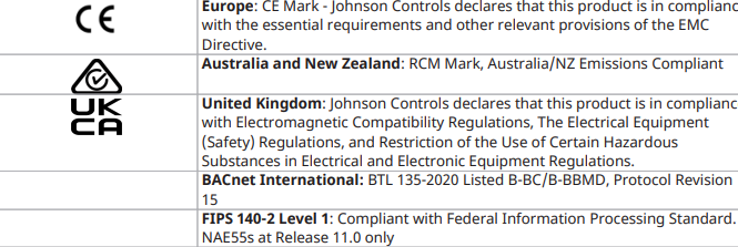
Europe: CE Mark - Johnson Controls, Inc. declares that this product is in
compliance with the essential requirements and other relevant provisions of
the EMC Directive.
Australia and New Zealand: RCM Mark, Australia/NZ Emissions Compliant
United Kingdom: Johnson Controls declares that this product is in compliance
with Electromagnetic Compatibility Regulations, The Electrical Equipment
(Safety) Regulations, and Restriction of the Use of Certain Hazardous
Substances in Electrical and Electronic Equipment Regulations.
BACnet International: BTL 135-2020 Listed B-BC/B-BBMD, Protocol Revision
15
Table 8: NAE55xx-3 (UL 916, Energy Management) and NAE5510-3U (UL 864, Smoke Control) technical
specifications
Power requirement Dedicated nominal 24 VAC, Class 2 power supply (North America), SELV power
supply (Europe), at 50/60 Hz (20 VAC minimum to 30 VAC maximum)
Power consumption 50 VA maximum
Table 8: NAE55xx-3 (UL 916, Energy Management) and NAE5510-3U (UL 864, Smoke Control) technical
specifications
Ambient operating
conditions
0°C or 32°F to 50°C or 122°F; 10% to 90% RH, 30°C or 86°F maximum dew point
Ambient storage conditions -40°C or -104°F to 70°C or 158°F; 5% to 95% RH, 30°C or 86°F maximum dew
point
Data protection battery Supports data protection on power failure. Rechargeable gel cell battery: 12 V,
1.2 Ah, with a typical life of 3 to 5 years at 21°C (70°F); Product Code Number:
MS-BAT1010-0
Clock battery Maintains real-time clock through a power failure. Onboard cell; typical life 10
years at 21°C or 70°F
Processor 1.46 GHz Intel® Atom® Bay Trail E3815 processor for MS-NAE55xx-3 models
Memory 16 GB flash nonvolatile memory for operating system, configuration data, and
operations data storage and backup for MS-NAE55xx-3 models.
2 GB DDR3 SDRAM for operations data dynamic memory for all models
Operating system NAE5510-3U (UL 864 UUKL 10th ed /S527 UUKL7 4th ed): OEM Version of
Microsoft® Windows® Embedded Standard 7 with SP1 (WES7)
NAE55xx-3: (UL 916): Wind River® Linux LTS 17 (LTS=long-term support)
Network and serial
interfaces
• One Ethernet port; 10/100/1000 Mbps; 8-pin RJ-45 connector
• Two optically isolated RS-485 ports; 9.6k, 19.2k, 38.4k, or 76.8k baud;
pluggable and keyed 4 position terminal blocks, RS-485 terminal blocks
available on NAE55 models only
• Two RS-232-C serial ports, with standard 9-pin sub-D connectors, that
support all standard baud rates
• Two USB 2.0 serial ports; standard USB connectors support an optional,
user-supplied external modem, no longer supported at Release 10.0 or later
• One LonWorks port; FTT10 78 Kbps; pluggable, keyed 3-position terminal
block. LonWorks port available on NAE552x-x models only
Housing Plastic housing with internal metal shield
Plastic material: ABS + polycarbonate; Protection: IP20 (IEC 60529)
Mounting On a flat surface with screws on four mounting feet or on a dual 35 mm DIN
rail
Dimensions
(Height x Width x Depth)
226 mm x 332 mm x 96.5 mm or 8.9 in. x 13.1 in. x 3.8 in. including mounting
feet
Minimum space for mounting: 303 mm x 408 mm x 148 mm or 12.0 in. x 16.1
in. x 5.8 in.
Shipping weight 2.9 kg or 6.4 lb
Compliance United States: UL Listed, File E107041, CCN PAZX, UL 916, Energy
Management Equipment, FCC Compliant to CFR47, Part 15, Subpart B, Class A
UL Listed, File S4977, UL 864 UUKL/UUKLC 10th Edition Listed, Smoke Control
Units and Accessories for Fire Alarm Systems Equipment (MS-NAE5510-3U
model only with Release 8.1 software)
Canada: UL Listed, File E107041, CCN PAZX7, CAN/CSA C22.2 No. 205, Signal
Equipment, Industry Canada Compliant, ICES-003
UL Listed, File S4977, UL 864 UUKL/ORD-C100-13 10th Edition Listed, Smoke
Control Units and Accessories for Fire Alarm Systems. MS-NAE5510-3U model
only with Release 8.1 software
Table 8: NAE55xx-3 (UL 916, Energy Management) and NAE5510-3U (UL 864, Smoke Control) technical
specifications
North American emissions
compliance
United States
This equipment has been tested and found to
comply with the limits for a Class A digital device
pursuant to Part 15 of the FCC Rules. These limits
are designed to provide reasonable protection
against harmful interference when this equipment
is operated in a commercial environment. This
equipment generates, uses, and can radiate radio
frequency energy and, if not installed and used in
accordance with the instruction manual, may cause
harmful interference to radio communications.
Operation of this equipment in a residential area
may cause harmful interference, in which case the
users will be required to correct the interference at
their own expense.
Warning (Part 15.21)
Changes or modifications not expressly approved by
the party responsible for compliance could void the
user’s authority to operate the equipment.
Canada
This Class (A) digital apparatus meets all the
requirements of the Canadian Interference-Causing
Equipment Regulations.
Cet appareil numérique de la Classe (A) respecte
toutes les exigences du Règlement sur le matériel
brouilleur du Canada.
Industry Canada Statement(s)
This device complies with Industry Canada licenceexempt RSS standard(s). Operation is subject to the
following two conditions:
1. This device may not cause interference, and
2. This device must accept any interference,
including interference that may cause
undesired operation of the device.
Le présent appareil est conforme aux CNR
d'Industrie Canada applicables aux appareils radio
exempts de licence. L'exploitation est autorisée aux
deux conditions suivantes :
1. L'appareil ne doit pas produire de brouillage, et
2. L'utilisateur de l'appareil doit accepter tout
brouillage radioélectrique subi, même si le
brouillage est susceptible d'en compromettre le
fonctionnement.
-
 HIRSCHMANN MSM20-M2M2M2M2SY9HH9E Ethernet media modul
 -
 HIRSCHMANN SPIDER-PL-20-05T1999999TWVHHHH Industrial Ethernet Rail Switch
 -
 Hirschmann SPIDER-PL-20-07T1M2M299TWVHHHH Industrial ETHERNET Rail Switch
 -
.png) Hirschmann (Belden) RS20-1600M2M2SDAEHC09.1.00 DIN-rail managed industrial Fast Ethernet switch
Hirschmann (Belden) RS20-1600M2M2SDAEHC09.1.00 DIN-rail managed industrial Fast Ethernet switch -
 Hirschmann (Belden) RS30-1602O6O6TDAPHC09.1.00 DIN-rail managed industrial Ethernet switch
 -
 Hirschmann (Belden) RS30-2402O6T1SDAPHH09.0.13 DIN-rail industrial Ethernet switch
 -
Hirschmann (Belden) SPIDER-PL-20-04T1S29999TY9HHHH Ethernet DIN-rail switch
-
 HIRSCHMANN RS20-1600T1T1SDAUHX Switch
 -
 HIRSCHMANN BRS42-0012OOOO-SPCZ99HHSES industrial switch
 -
 Hirschmann RS20-0800S2S2TDHPHH09.0.14 Fast Ethernet DIN rail switch.
 -
 HIRSCHMANN MM20-Z6Z6M2M2SAHH Hybrid Fast Ethernet Media Module
 -
 HIRSCHMANN MM20-Z6Z6T1T1SAHH hot-swappable hybrid Fast Ethernet Media Module
 -
 HIRSCHMANN MM20-P9P9T1T1SAHH Hybrid Fast Ethernet Media Module
 -
 HIRSCHMANN MM20-M4T1T1T1SAHH Hybrid Fast Ethernet Media Module
 -
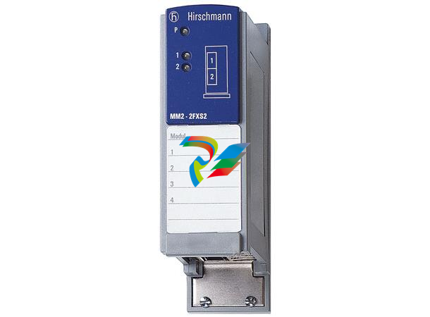 HIRSCHMANN MM20-M4M4T1T1SAHH Hybrid Fast Ethernet Media Module
 -
 HIRSCHMANN MM20-M2M2M2M2SZHH Ethernet media module
 -
HIRSCHMANN MM20-M2M2M2M2SAHH Ethernet media module
-
 HIRSCHMANN MM20-T1T1T1T1EBH 4-port Fast Ethernet Copper Cable Media Module
 -
HIRSCHMANN MM20-T1T1T1T1SAHH 4-port Fast Ethernet Copper Cable Media Module
-
HIRSCHMANN MM20-T1T1T1T1SAHH 4-port Fast Ethernet Copper Cable Media Module
-
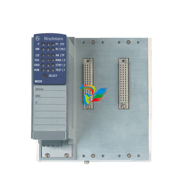 HIRSCHMANN MM20-Z6Z6EBH Hot-swappable fast Ethernet media module
 -
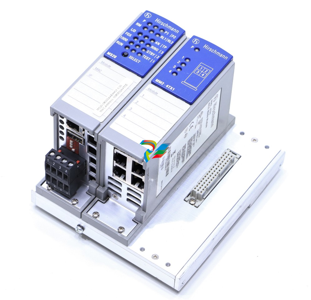 HIRSCHMANN MM20-Z6Z6SAHH Ethernet media module
 -
HIRSCHMANN MM20-Z6Z6Z6Z6EBH Industrial Media Module
-
 MSM40-T1T1T1TZ9HH9E99.9.99 HIRSCHMANN Switch
 -
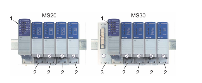 HIRSCHMANN MS20-0800SAAEHC / MS20-0800SAAEHC0 8-port modular Layer 2 management Ethernet switch
 -
 Hirschmann RSPM20-4T14T1SZ9HHS9 Switch RSPM20-4T14T1SZ9HHS9
 -
 HIRSCHMANN RS20-1600M2M2SDAEHH09.1. RS20/30/40 Managed Switch configurator
 -
HIRSCHMANN RS20-1600M2M2SDAEHX09.0.00 Ethernet switch
-
 HIRSCHMANN BELDEN SPIDER-PL-20-07T1M2M299TY9HHHH / SPIDERPL2007T1M2M299TY9HHHH
 -
HIRSCHMANN MM3-1FXS2/3TX1 Switching Board Module
-
 HIRSCHMANN RSPE30-24044O7T99-ECCP999HHSE2A08.1.00 Industrial-grade fanless management-type Ethernet switch
 -
 HIRSCHMANN RS30-1602OOZZSDAEHC09.1.00 DIN-rail-mounted managed Layer 2 Ethernet switch
 -
 HIRSCHMANN MACH104-20TX-F Managed 24-port Full Gigabit 19" Switch
 -
 HIRSCHMANN Switch RS20-0800M4M4SDAE
 -
Hirschmann RS30-1602O6O6SDAEHH09.1. Management-type Ethernet switch
-
 Hirschmann RS30-1602OOZZSDAEHC09.0.10 Open rack-style Ethernet switch
 -
 HIRSCHMANN RSPE30-24044O7T99-SCCV999HHSI2SXX.X.XX High-Availability Seamless Redundancy
 -
HIRSCHMANN RSPE30-24044O7T99-SCCZ999HHSE2A DIN-rail Ethernet switch
-
HIRSCHMANN MM2-4TX1-EEC switch
-
HIRSCHMANN MSM40-T1T1T1T1TZ9HH9E99.9.99 Module
-
 HIRSCHMANN RS20 Rail Switch RS20-0400S4T1SDAEHC07.1.01
 -
 HIRSCHMANN M4-FAST8-SFP Fast Ethernet media module
 -
 HIRSCHMANN RS20-0400M2T1SDAP Managed Fast-Ethernet-Switch
 -
 HIRSCHMANN BELDEN SPIDER II 8TX/1FX EEC Industrial Ethernet Rail Switch
 -
HIRSCHMANN MM3-2FXS2/2TX1
-
 HIRSCHMANN RS2-4TX/1FX EEC Industrial Ethernet Rail Switch
 -
 RS30-0802O6O6SDAEHC09.0.10 HIRSCHMANN Switch
 -
 HIRSCHMANN m4-8TP-RJ45 Ethernet Media Module
 -
 HIRSCHMANN MSP30-24040SCZ9URHHE3A switch
 -
 Hirschmann rack MS30-1602SAAPHC
 -
 HIRSCHMANN RS2-FX/FX Industrial Switch Module
 -
Rs1txfx - Hirschmann - Rs1-Tx/Fx Rail Switch
-
RS20-0800S2S2SDAEHC09.1.00 HIRSCHMANN Commutator
-
 Hirschmann EAGLE20 TX/TX Industrial Security Router
 -
 Hirschmann SPIDER-SL-20-04T1S29999SY9HHHH Industrial Switch
 -
 HIRSCHMANN MAR1040-4C4C4C4C9999SMMHRHHXX.X. Gigabit Ethernet Switch configurator
 -
 Hirschmann MAR1040 Industrial Switch
 -
 HIRSCHMANN BELDEN RS30-1602O6O6SDAE
 -
Hirschmann RS20-1600M2M2SDAUHC Ethernet DIN rail switch
-
 HIRSCHMANN OCTOPUS 24M industrial switch
 -
 HIRSCHMANN RS20-1600T1T1SDAE Management-type Ethernet switch
 -
 HIRSCHMANN RS20-1600T1T1SDAUHH industrial switch
 -
HIRSCHMANN RS20-0800M2M2SDAPHC09.0.04 switch
-
 Hirschmann MR 8-03 24V DC Industrial Modular Bridge/Router
 -
 HIRSCHMANN RS20-0400M2T1SDAPHC08.0.01 Managed Switch
 -
 MACH1130 Hirschmann Industrial Switch
 -
 HIRSCHMANN 943824-002 SPIDER 5TX Industrial Ethernet Switch
 -
 HIRSCHMANN RS30-0802O6O6SDAEHC09.1.00 Managed Industrial Switch
 -
 HIRSCHMANN RS20-0400M2M2TDAEHC04.0.01 Industrial Switch
 -
 HIRSCHMANN BRS20-0600Z6Z6-STCZ99HHSES Industrial Switch
 -
 HIRSCHMANN MACH104-20TX-FR-L3P Industrial Ethernet Switch
 -
 HIRSCHMANN RS40-0009CCCCEDBPHH06.0.01 Industrial Switch
 -
 HIRSCHMANN RS2-3TX/2FX EEC Industrial Ethernet Switch
 -
 Hirschmann MACH 1020/1030 Fast/Gigabit Rack Mount Switches
 -
HIRSCHMANN RS20-0800M2M2SDAPHC09.0.14 Industrial Switch
-
 HIRSCHMANN RS20-1600T1T1SDAEHC09.0.04 Industrial Switch
 -
 HIRSCHMANN RSB20-0800T1T1EAABHH Industrial Switch
 -
 HIRSCHMANN MACH4002-48+4G-L3E Industrial Backbone Switch
 -
 HIRSCHMANN RS20-0400S2T1SDAE Industrial Managed Switch
 -
HIRSCHMANN RS20-0800S2T1SDAUHC Industrial Switch
-
 HIRSCHMANN RS20-2400S4S4SDAEHC09.0.14 industrial switch
 -
 HIRSCHMANN OS20-001200T5T5T5- TBBZ999HHNE3S 08.1.00 industrial switch
 -
HIRSCHMANN OS20-001200T5T5T5- TBBZ999HHNE3S 08.1.00 industrial switch
-
 HIRSCHMANN RS40-0009CCCCSDAEHH09.0.14 switch
 -
 Hirschmann RS20-1600T1T1SDAUHC Management-type Ethernet Switch
 -
 Hirschmann M1-8SFP Switche
 -
Hirschmann Industrial Ethernet Ruggedized Switch MACH1000 Family
-
 Basler Electric, Solid State Protective Relay, BE1-60
 -
BASLER ELECTRIC SR4A-2B15B3A Static Voltage Regulator
-
.png) BASLER ELECTRIC EXCITER DIODE MONITOR EDM-200
BASLER ELECTRIC EXCITER DIODE MONITOR EDM-200 -
.png) BASLER ELECTRIC DECS125-15-B2C5 DIGITAL EXCITATION CONTROL SYSTEM V 2.0.9
BASLER ELECTRIC DECS125-15-B2C5 DIGITAL EXCITATION CONTROL SYSTEM V 2.0.9 -
 BASLER ELECTRIC BE1-851 OVERCURRENT PROTECTION RELAY MECHANISM
 -
 Basler Electric BE1-51A / BE151A
 -
 Basler Electric BE1-40Q Loss of Excitation Relay
 -
 Basler Electric BE1-87G Variable Percentage Differential Relay
 -
 Basler Electric BE1-11 Protection System I5A3M2P2N0EA00
 -
 BASLER ELECTRIC DECS-200-1C Digital Excitation Control System
 -
 Basler Electric / Kohler BE1-11g Generator Protection Relay G5A3M2J2N0E000
 -
BASLER ELECTRIC DECS125-15 DIGITAL EXCITATION CONTROL SYSTEM
-
 BASLER ELECTRIC BE1-951 OverCurrent Protecton System
 -
Basler Electric DECS-200-1L Digital Excitation Control System
-
 Basler Electric DGC-2020HD-5NS1DNSBA Digital Genset Controller -
 -
 BASLER ELECTRIC BE1-81T1EE1WA0N1F / BE181T1EE1WA0N1F
 -
 BASLER ELECTRIC BE1-25M1EA6PN5R1F / BE125M1EA6PN5R1F
 -
 BASLER ELECTRIC DECS-250-LN1SN1N DIGITAL EXCITATION CONTROL SYSTEM
 -
Basler Electric DECS-250-CN2CN 1N Digital Excitation Control System Unit
-
 BASLER ELECTRIC DECS-300-C0N0 DIGITAL EXCITATION CONTROL SYSTEM
 -
 BASLER ELECTRIC BE1-87T-A1E-A1J-D0S1F / BE187TA1EA1JD0S1F
 -
BASLER ELECTRIC BE1-11-G6D1M0J2P0E000 Protection System
-
 BASLER ELECTRIC BE1-GPS100-E4N1H1N GENERATOR PROTECTION SYSTEM
 -
 Jaquet Relay card (Auxiliary module) FTV 3090 377Z-03985
 -
 Jaquet Trip Chain Control card FTBU 3034 377Z-05030
 -
 Jaquet with input card -E04 FTFU 3024 -E04 377Z-05855
 -
 Jaquet with input card -E03 FTFU 3024- E03 377Z-03983
 -
 Jaquet FTFU 3024- E02 377Z-03982 with input card -E02
 -
 Jaquet FTFU 3024-E01 377Z-03981 with input card -E01
 -
 Hirschmann RS20-2400T1T1SDAE Industrial Managed Ethernet Switch
 -
 Hirschmann BELDEN EAGLE30-04022O6TT999SCCV9HSE3F
 -
 Hirschmann MM3-2FXS2/2TX MICE Media Module
 -
 Hirschmann RS20-1600M2M2SDAPHC08.0.05 Industrial Managed Switch
 -
 Hirschmann OZD Profi 12M G12-1300 PRO Fieldbus Repeater
 -
Hirschmann SPIDER 4TX/1FX-ST EEC Industrial Ethernet Switch
-
 Hirschmann MM2-2FXM3/2TX1 MICE Media Module
 -
 Hirschmann RS20-2400M2M2SDAPHC09.0.14 Industrial Switch
 -
 Hirschmann RS20-0400M2M2SDAEHC07.1.05 OpenRail Switch
 -
 Hirschmann OZD Profi 12M G12-EEC Fieldbus Repeater
 -
HIRSCHMANN MDA422-1/2-3.5c-23/46 sensor
-
Hirschmann RS30-2402T1T1SDAUHC Managed Industrial Switch


