
Woodward 723PLUS Digital Control
attenuation of the RF signals from the control can be guaranteed, no additional
special measures are needed. The signals in the 156–165 MHz range must be
attenuated by 6 dB before they reach the receiver antenna or receiver
(interference point), and the control must be >3 m away from the antenna or
receiver. This is a specific installation dependency, and some examples may
include:
A grounded, metal, IP rated cabinet with all cabling staying inside it for more
than 2 m length, with any shield terminations at the cabinet exit/entry point
and all unshielded cable routed directly against the metal cabinet.
A below-deck metal engine room where none of the cabling, including power,
leaves the engine room.
If using a specific installation location or method as a means to meet the Marine
Notch requirements, instead of a secondary metal shield for cabling, consult the
ship builder. Acceptability of the installation for obtaining 6 dB of RF attenuation
in the 156–165 MHz range must be provided by the ship builder. Woodward will
not know the ship installation application or requirements to provide guidance.
Internal Jumpers
The 723PLUS control has ten, two-position internal jumpers (JPR1 through
JPR20) located on the top of the printed circuit board. If it is necessary to change
any jumper to match your control requirements, and this suits the nature of the
software, be sure to read page v, Electrostatic Discharge Awareness.
Remove power and all inputs. Wait 45 seconds, then remove cover. With your
fingers or a small pair of tweezers, carefully remove the appropriate jumper and
replace it securely over the proper two connectors (see Figure 2-1).
Notes for Figure 2-2
Shielded wires are twisted pairs, with shield grounded at one end only. When
mounting control to bulkhead, use the grounding stud and hardware supplied with
the chassis to ensure proper grounding.
Shields must not be grounded at any external point unless otherwise noted.
All shields must be carried continuously through all terminal blocks and must not be
tied to other shields except at the common ground point. Tie all shields together at
ground stud located near connector J1.
Remove jumper for voltage input.
Remove jumper if using external discrete input power.
Discrete inputs are isolated from other circuits and intended to be powered by
TB1-39 (+24) leaving the jumper in place. Input current is nominally 10 mA input into
2210 Ω.
7. Unless otherwise specified:
A. Relays shown de-energized
B. Relays energize for function
C. Relay contact ratings for minimum 100 000 operations:
Resistive— 2.0 A at 28 Vdc
0.1 A at 115 Vac 50 to 400 Hz
Inductive— 0.75 A at 28 Vdc 0.2 Henry
0.1 A at 28 Vdc lamp
Analog output signals to other systems must be isolated from ground either by
design or employment of isolation amplifiers.
Analog input signals to other systems must be isolated from ground either by design
or employment of isolation amplifiers.
10. Factory set for MPU input.
11. Factory set for 20–160 mA output.
12. Factory set for 4–20 mA output.
13. Internal power supply provides dc isolation between the power source and all other
inputs and outputs.
14. Communication port J1 can be used with the Woodward ST2000 Hand Held
Programmer or PC Interface using Watch Window/Servlink software.
15. Communication port J2 or J3 can be configured as an RS-232. RS-422. or RS-485
serial interface. Port configuration can be done in the application software only. For
the pin assignment of J2 and J3. see later in this chapter.
16. This analog output may connect to a metering/controlling device. The shield should
be continuous between all connected devices with a single shield termination point to
ground.
17. Use twisted pair shielded wires only.
18. Remove jumper if used with the gas engine I/O node.
Termination is accomplished using a three-resistor voltage divider between a
positive voltage and ground. The impedance of the resistor network should be
equal to the characteristic impedance of the cable. This is usually about 100 to
120 ohms. The purpose is to maintain a voltage level between the two differential
lines so that the receiver will be in a stable condition. The differential voltage can
range between 0.2 and 6 volts; but the maximum voltage between either receiver
input and circuit ground must be less than 10 volts. There is one termination
resistor network for each port located on the 723PLUS board. Connection to this
resistor network is made through the 9-pin connectors on pins 6 and 9. See
Figures 2-5 through 2-8 for termination and cable connection examples.
Due to the variety of installations, plus system and component tolerances, the
723PLUS control must be tuned to each system for optimum performance.
This chapter contains information on how to enter control set points through the
control's menu system using the Hand Held Programmer. If you have access to
the Watch Window software tool and Servlink software, you can set up and tune
the 723PLUS control from a PC (personal computer) using the instructions in
Chapter 5 of this manual.
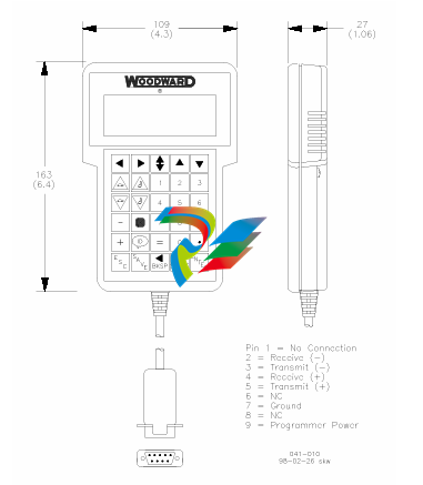
Hand Held Programmer and Menus
The Hand Held Programmer is a hand-held computer terminal that gets its power
from the 723PLUS control. The terminal connects to the RS-422 communication
-
 Hirschmann M1-8SFP Switche
 -
 Hirschmann Industrial Ethernet Ruggedized Switch MACH1000 Family
 -
 Basler Electric, Solid State Protective Relay, BE1-60
 -
BASLER ELECTRIC SR4A-2B15B3A Static Voltage Regulator
-
.png) BASLER ELECTRIC EXCITER DIODE MONITOR EDM-200
BASLER ELECTRIC EXCITER DIODE MONITOR EDM-200 -
.png) BASLER ELECTRIC DECS125-15-B2C5 DIGITAL EXCITATION CONTROL SYSTEM V 2.0.9
BASLER ELECTRIC DECS125-15-B2C5 DIGITAL EXCITATION CONTROL SYSTEM V 2.0.9 -
 BASLER ELECTRIC BE1-851 OVERCURRENT PROTECTION RELAY MECHANISM
 -
 Basler Electric BE1-51A / BE151A
 -
 Basler Electric BE1-40Q Loss of Excitation Relay
 -
 Basler Electric BE1-87G Variable Percentage Differential Relay
 -
 Basler Electric BE1-11 Protection System I5A3M2P2N0EA00
 -
 BASLER ELECTRIC DECS-200-1C Digital Excitation Control System
 -
 Basler Electric / Kohler BE1-11g Generator Protection Relay G5A3M2J2N0E000
 -
BASLER ELECTRIC DECS125-15 DIGITAL EXCITATION CONTROL SYSTEM
-
 BASLER ELECTRIC BE1-951 OverCurrent Protecton System
 -
Basler Electric DECS-200-1L Digital Excitation Control System
-
 Basler Electric DGC-2020HD-5NS1DNSBA Digital Genset Controller -
 -
 BASLER ELECTRIC BE1-81T1EE1WA0N1F / BE181T1EE1WA0N1F
 -
 BASLER ELECTRIC BE1-25M1EA6PN5R1F / BE125M1EA6PN5R1F
 -
 BASLER ELECTRIC DECS-250-LN1SN1N DIGITAL EXCITATION CONTROL SYSTEM
 -
Basler Electric DECS-250-CN2CN 1N Digital Excitation Control System Unit
-
 BASLER ELECTRIC DECS-300-C0N0 DIGITAL EXCITATION CONTROL SYSTEM
 -
 BASLER ELECTRIC BE1-87T-A1E-A1J-D0S1F / BE187TA1EA1JD0S1F
 -
BASLER ELECTRIC BE1-11-G6D1M0J2P0E000 Protection System
-
 BASLER ELECTRIC BE1-GPS100-E4N1H1N GENERATOR PROTECTION SYSTEM
 -
 Jaquet Relay card (Auxiliary module) FTV 3090 377Z-03985
 -
 Jaquet Trip Chain Control card FTBU 3034 377Z-05030
 -
 Jaquet with input card -E04 FTFU 3024 -E04 377Z-05855
 -
 Jaquet with input card -E03 FTFU 3024- E03 377Z-03983
 -
 Jaquet FTFU 3024- E02 377Z-03982 with input card -E02
 -
 Jaquet FTFU 3024-E01 377Z-03981 with input card -E01
 -
 Hirschmann RS20-2400T1T1SDAE Industrial Managed Ethernet Switch
 -
 Hirschmann BELDEN EAGLE30-04022O6TT999SCCV9HSE3F
 -
 Hirschmann MM3-2FXS2/2TX MICE Media Module
 -
 Hirschmann RS20-1600M2M2SDAPHC08.0.05 Industrial Managed Switch
 -
 Hirschmann OZD Profi 12M G12-1300 PRO Fieldbus Repeater
 -
 Hirschmann SPIDER 4TX/1FX-ST EEC Industrial Ethernet Switch
 -
 Hirschmann MM2-2FXM3/2TX1 MICE Media Module
 -
 Hirschmann RS20-2400M2M2SDAPHC09.0.14 Industrial Switch
 -
 Hirschmann RS20-0400M2M2SDAEHC07.1.05 OpenRail Switch
 -
 Hirschmann OZD Profi 12M G12-EEC Fieldbus Repeater
 -
 HIRSCHMANN MDA422-1/2-3.5c-23/46 sensor
 -
Hirschmann RS30-2402T1T1SDAUHC Managed Industrial Switch
-
 Hirschmann OZD GENIUS G12 Industrial Switche
 -
 Hirschmann OZD 485 G12-1300 PRO Fieldbus Repeater
 -
 Hirschmann MM2-2FXM2 MICE Media Module
 -
 Hirschmann RS20-1600S2T1SDAUHC Managed Industrial Switch
 -
 Hirschmann MS20-0800SAAEHH04.2.04 MICE Switch
 -
 Hirschmann SPIDER 4TX/1FX EEC Unmanaged Industrial Switch
 -
 HIRSCHMANN MS4128-L3P EEC Managed Industrial Ethernet Switch
 -
 HIRSCHMANN RS20-0400M2T1SDAPHC08.0.01 Managed Switch
 -
 ETEL EA-S0M-400-40/80A-0000-00 AccurET Modular Power Supply
 -
 ETEL EA-B0I-0-0-0000-00 Backplane Interface Board
 -
 ETEL EA-P2M-400-15/40A-0100-00 Position Controller
 -
ETEL EA-P2M-400-15/40A-0000-00 Position Controller
-
 ETEL EA-P2M-400-10/20A-0100-01 Position Controller
 -
 ETEL EA-P2M-400-10/20A-0000-01 Position Controller
 -
 ETEL EA-P2M-400-5/10A-0100-01 Position Controller
 -
 ETEL EA-P2M-048-2.5/5A-0000-01 Modular Position Controller
 -
 ETEL EA-S0M-300-40/80A-0000-00 Power Supply Module
 -
 ETEL EA-P2M-300-07/15A-0100-01 Position Controller
 -
 ETEL EA-P2M-300-07/15A-0000-01: Modular Position Controller
 -
 ETEL EA-P2M-300-4/7.5A-0100-01 Overview
 -
 Basler Electric MOC2. Motor Operated Potentiometer
 -
 Basler Electric BE1-11 RTD Module, Resistance Temperature Detector
 -
 Basler Electric RDP-110C, Remote Display Panel
 -
 Basler Electric VRM-2020. Voltage Regulation Module
 -
 Basler Electric IDP-1500. Interactive Display Panel
 -
 Basler Electric AEM-2020. Analog Expansion Module
 -
 Basler Electric IDP-2020. Interactive Display Panel
 -
 Basler Electric CEM-2020. Contact Expansion Module
 -
 Basler Electric CEM-125. Contact Expansion Module
 -
 Basler Electric BE2000E, Digital Voltage Regulator
 -
 Basler Electric SMC-150. Synchronous Motor Controller
 -
 Basler Electric AVC125-10. Voltage Regulator
 -
 Basler Electric BE1-25. Sync-Check Relay
 -
 Basler Electric DGC-2020ES, Digital Genset Controller
 -
 ETEL EA-P2M-400-5/10A-0000-01 Position Controller
 -
 Basler Electric BE1-64F, Ground Fault Relay
 -
 Basler Electric BE1-79M, Multi Shot Reclosing Relay
 -
 Basler Electric BE1-81O/U, Digital Frequency Relay
 -
 Basler Electric BE1-87B, High Impedance Bus Differential Relay
 -
 Basler Electric BE1-79A, Reclosing Relay
 -
 Basler Electric BE1-27. BE1-59. BE1-27/59. Voltage Relay
 -
 Basler Electric SMC-250. Synchronous Motor Controller
 -
 Basler Electric SGC-250N, Synchronous Generator Controller
 -
 Basler Electric SGC-250. Synchronous Generator Controller
 -
 Basler Electric BE1-50/51 Plug and Play and Retrofit Relays
 -
 Basler Electric DECS-2100. Digital Excitation Control System
 -
 Basler Electric DECS-250E, Digital Excitation Control System
 -
 Basler Electric BE1-700V, Voltage Only Digital Protective Relay
 -
 Basler Electric DECS-250. Digital Excitation Control System
 -
 Basler Electric DECS-450. Digital Excitation Control System
 -
 Basler Electric DECS-150. Digital Excitation Control System
 -
 Basler Electric ES-49. Temperature Relay
 -
 Basler Electric ES-81O/U, ES-81O,ES-81U Overfrequency Relay
 -
Basler Electric ES-74V, DC Voltage Sensing Relay
-
Basler Electric ES-27/59. Under/Overvoltage Relay
-
 Basler Electric ES-27. Undervoltage Relay
 -
 Basler Electric ES-25. Sync-Check Relay
 -
 Basler Electric ES-47, ES-47N Phase Sequence Relay
 -
Basler Electric ES-37.ES-37/51 Undercurrent Relay
-
 Basler Electric ES-32. Reverse Power Relay
 -
Basler Electric ES-59. Overvoltage Relay
-
 Basler Electric ES-55. Power Factor Relay
 -
 Basler Electric DGC-2020HD, Digital Genset Controller
 -
 Basler Electric BE1-FLEX, Protection, Automation, and Control System
 -
 Schneider GUTOR OC0935 Power Factor Sampling Board
 -
 Schneider GUTOR OC0922 Analog Signal Isolation Board
 -
 Schneider GUTOR OC0908 Battery Voltage Detection Board
 -
Schneider GUTOR OC0947 Temperature / IGBT Sampling Board
-
 Schneider GUTOR OP2601 Communication Expansion Board
 -
 Schneider Electric GUTOR OP2312 bypass control board
 -
 Schneider Electric GUTOR OP2130 Cooling Fan Monitoring & Control Board
 -
 Schneider Electric GUTOR OP2010 Battery Test Board / Battery Management Diagnostic Card
 -
Schneider Electric GUTOR OP2552 Three-phase Power Connection Board Assembly
-
 Schneider Electric GUTOR OP1922A Parallel Control Board / Load-Sharing Synchronization Module
 -
 Schneider Electric GUTOR OP6290B Inverter Feedback Acquisition Board / Signal Scaling Module
 -
Schneider GUTOR OP6280 Basic Signal Board
-
Schneider Electric GUTOR OP2456 / OP2456B Main control board
-
 Schneider Electric GUTOR OP2452 Power Plug-in Panel
 -
 Schneider Electric GUTOR OP2450 Parallel Communication Board
 -
Schneider Electric GUTOR OP2406 Interface Fuse Monitoring Board
-
 Schneider Electric GUTOR OC0919 High-Power Semiconductor Module
 -
 Schneider Electric GUTOR OP6281A System Logic Interface Board
 -
 Schneider Electric GUTOR OP6285A Power Signal Acquisition Board
 -
 Schneider Electric GUTOR OP2438 Fan Monitor & Drive Protection Board
 -
Schneider Electric GUTOR OP2446 Main Control CPU Board


