
Woodward 8290-189-EPG-installation-manual 8290-044
8290-189-EPG-installation-manual 8290-044
Installation and Operation Manual
This manual covers Electrically Power Governor (EPG) models 512/524 and
1712/1724. Refer to the appropriate manual or contact Woodward for information
about other versions of the EPG.

Application
The EPG is used to control the speed of diesel, gas, and gasoline engines. It can
also control the speed of gas turbines. Installation of EPG actuators is simple
because they require neither mechanical drive nor hydraulic supply.
The EPG handles prime movers with mechanical loads and generator loads
equally well. Generator sets which will be paralleled, however, require additional
appropriate switch gear, current and potential transformers, and the Woodward
Generator Load Sensor.
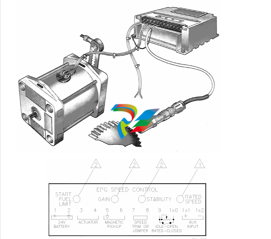
An EPG is a three-component system, requiring a magnetic pickup, speed
control, and actuator.
A battery charger must be used to keep the battery charged. Maximum steady
state current consumption is 4 A for the 12-volt models (512/1712), and 3 A for
the 24-volt models (524/1724).
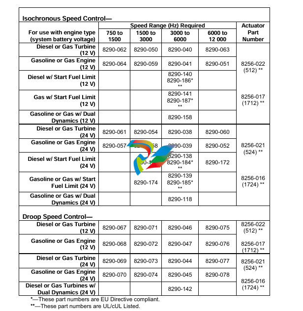
Part Number Selection
Use EPG Model 512/1712 for operation in 12-volt systems. Use Model 524/1724
for operation in 24-volt systems.
Additionally, speed controls are available for four ranges of magnetic pickup
frequencies, for diesel engines and gas turbines, or for gasoline and gas
engines. Actuators have a double-ended output shaft for either clockwise or
counterclockwise rotation to increase fuel.
Speed controls and actuators must be compatible. Use the Part Number
Selection Table below (Table 1-1) to choose compatible EPG speed controls and
actuators.
The optional Start Fuel Limit feature allows setting a maximum actuator position
during start-up. The maximum position remains in effect until the engine reaches
the selected idle or rated speed. The limit may be adjusted out of the way by
turning the adjustment potentiometer fully clockwise.
The Dual Dynamics feature allows tailoring a special set of responses for
unloaded and loaded operating conditions. This type of control is often needed
for gas engines and other systems with non-linear fuel systems. A switch is used
to change between slow and fast dynamics.
Accessories
This manual includes some information about accessories frequently used with
EPGs.
To Parallel Generators
Add the Generator Load Sensor to the EPG in paralleled generator applications.
Woodward makes many accessories for paralleled generator applications.
To Decrease Acceleration and Deceleration
The Ramp Generator or an optional, external capacitor can be used to increase
the time to go from idle to rated speeds and vice versa. The Ramp Generator
provides a linear ramp with times adjustable to 25 seconds in a typical case. It is
useful in smoke-limiting applications. Use the 8271-909 with 24 V batteries and
the 8271-910 for 12 V batteries. The capacitor provides an exponential ramp with
times up to four seconds. Exponential means it changes (speed in this case)
rapidly at first but slows as it approaches its final value. See the typical wiring
diagram for capacitor requirements.
References
These publications can be obtained from your Woodward authorized Distributor
or AISF (Authorized Independent Service Facility). All are also available on the
Woodward website (www.woodward.com).
Catalog
52122
Product
Specification
04106
Manual
25070
82510
Title
Woodward Industrial Control Product Line Catalog
Title
Model 512/1712 & 524/1724 Electrically Powered Governors
Title
Electric Governor Installation Guide
Magnetic Pickups for Electric Governors
direction of rotation for increased fuel by choosing a suitable linkage.
If you are using a Woodward supplied installation kit, follow its instructions and
skip over Linkage Compatibility. Begin again with Installing the Magnetic Pickup.
Linkage Compatibility
Also match linkage linearity to the fuel control. Use a linear linkage as shown in
Figure 2-2 unless the prime mover has a carburetor or other non-linear fuel
control. See Figures 2-3 and 2-4 for a carburetor compensating linkage. Contact
Woodward if a linkage different from those shown is required. Incorrect linearity
matching can cause stable operation at some fuel settings but oscillation at other
fuel settings.
A return spring is included in the actuator. Do not use an additional return spring.
(Low force return springs that may be located in an engine’s valve cover usually
don’t affect EPG performance.)
Make sure that the actuator is capable of moving the fuel control to the maximum
and minimum limits. Let the fuel control limit actuator travel. Set the linkage so
that the actuator is just above minimum when the fuel control is at its minimum
stop and (except for Detroit Diesel engines) so that the actuator is just below
maximum when the fuel control is at its maximum stop. We recommend that
Woodward installation kits be used for Detroit Diesel engines.
Use good rod end connectors. The link connecting the actuator lever to the fuel
control lever must not be so long that it flexes when the prime mover is running.
Installing the Magnetic Pickup
Mount the magnetic pickup through a housing or rigid bracket. Make sure that
the sensed gear is of magnetic material. The gap between the pickup and the
outside diameter of the gear should be set to approximately 1.0 mm (0.04”) at the
closest point (radial runout). Using the pickup with small gears may require
spacing as close as 0.25 mm (0.010”).
If you cannot measure the gap directly, it can be set in this manner: with the
prime mover shut down, turn the pickup in (clockwise) until it touches the outside
diameter of a tooth. Then back out the pickup (counterclockwise) approximately
three-quarters of a turn. Run the gear slowly through 360 degree rotation to
check the clearance of the pickup. When the gap is set, tighten the jam nut
securely against the housing or bracket.
The standard pickup models require mating connectors, MS 3102R-18-3P. The
connectors are not furnished with the pickup, but may be ordered from
Woodward if desired. See manual 82510. Magnetic Pickups and Proximity
Switches for Electronic Controls, for more information
Wiring Instructions
Use a wiring diagram for the specific part number of your EPG system to make
all wiring connections. The wiring diagram is available from Woodward. Typical
wiring is shown in Figure 2-5.
Make all connections using insulated terminals. The wiring from actuator to
speed control and from the battery to the speed control must be as short as
possible. Maximum wiring lengths are:
Maximum Wiring Length Chart
EPG Model
14 AWG
(2 mm²)
Maximum Wire Length
12 AWG
(3 mm²)
512/1712
10 ft (3 m)
524/1724
20 ft (6 m)
35 ft (11 m)
75 ft (23 m)
The fuse and switch or circuit breaker must be in the non-grounded battery lead.
Use a fuse or circuit breaker as specified in the Switch and Fuse Requirements
Chart. Do not use a fuse of higher current rating. Starter relays make good EPG
power switches.
Installation Checks
Checks for all Applications
The following steps check only the speed control and actuator, which must work
correctly before paralleling the generator. Since most faults appear when the
prime mover is first run, this step-by-step approach eliminates most problems
before they occur. The main part of Chapter 5 (Troubleshooting) is doing these
checks.
If a Load Sensor is used, temporarily remove the wires at speed control terminals
11 and 12 and temporarily jumper terminals 11 to 12. The generator must not be
paralleled during these tests. If a Ramp Generator is used, temporarily remove
the wire at speed control terminal 10. If a capacitor is connected to terminal 10 to
provide a ramp between unloaded and loaded, it must be removed during this
test or calibration. Leave the idle-rated switch wiring connected. Do the checks in
the order indicated. Terminal numbers in this section refer to the speed control.
Check that all electrical connections are correctly made and terminal screws
are tight; the magnetic pickup is properly installed and the jam nut is tight;
the actuator and linkage are securely fastened. If start-fuel limit is present,
turn the adjustment fully clockwise during these tests. If dual dynamics are
present, set the switch closed for slow dynamics.
2. Do not start the prime mover now. Turn on governor power. If the fuse or
breaker opens as soon as power is applied, the battery polarity (terminals
14 and 15) is probably reversed. The actuator shaft can jump when power is
turned on, but must quickly come back to the minimum fuel position. Check
the battery voltage at terminal 1 (+) and 2 (–). It must be from 10 to 16 Vdc
for 512/1712 controls, and from 20 to 32 Vdc for 524/1724 controls.
Disconnect any wiring or jumper on terminal 7. Measure 7.2 ±1.0 V from
terminal 2 (–) to 7 (+) [terminals 2 (–) to 9 (+) for dual-dynamics control].
Reinstall the wiring to terminal 7 if voltage is correct. Do not use the control
if voltage is incorrect.
If idle speed is desired, connect a 50 kΩ potentiometer or fixed resistor to
terminals 9 and 10 as shown in the typical wiring diagram. To calculate the
value of a fixed resistor:
R = 17 kΩ
( Rated Speed
Idle Speed – 1 )
Put the idle-rated switch in the rated position or jumper terminals 9 and 10.
Measure the voltage from terminal 7 (+) to 2 (–). Put the idle-rated switch in
the idle position or remove the jumper. The voltage must increase. If it does
not increase, check the speed trim pot, if used, and the idle-rated switch
wiring.
If a signal generator with an isolated output is available, the failsafe and
actuator travel can be checked, Rated and idle speed can be preset. If a
signal generator is not available, skip to step 7.
Turn off governor power. Remove the magnetic pickup wires from terminals
5 and 6. Connect the signal generator to terminals 5 and 6. Set the output
between 2 and 10 Vrms. The wave form can be sine, square, or triangular.
Calculate the MPU frequency for idle and rated speeds (see part number
selection in Chapter 1).
Check Failsafe and Actuator Travel:
Set the signal-generator frequency to about half of idle speed. Set the idle
rated switch to rated. Turn the signal generator and governor power on. The
linkage must be at the maximum-fuel position. Except for Detroit Diesel
engines, verify that linkage travel is limited by the prime-mover fuel control,
not by the actuator stop. Turn the signal generator off and remove the
connections at terminals 5 and 6. The linkage should move to the minimum
fuel position. Verify that linkage travel is limited by the prime mover’s fuel
control, not by the actuator stop.
Preset Rated Speed:
Set the signal generator for MPU frequency at rated speed and connect it to
terminals 5 and 6. Put the idle-rated switch in the rated position. Set the
speed trim pot, if connected, to mid-position. Observe the linkage position.
If the linkage Is at the maximum fuel position:
Slowly turn the rated speed pot counterclockwise until the linkage just
begins to move to the minimum fuel position. Start Fuel (if present) must be
adjusted to the maximum clockwise position or the actuator will not move to
maximum.
If the linkage Is at the minimum fuel position:
Slowly turn the rated speed pot clockwise until the linkage just begins to
move to the maximum fuel position.
Continue to adjust the rated speed pot very slowly in the appropriate
direction, trying to stop the linkage between the minimum and maximum fuel
stops. Because it is not possible to stop the motion, cease adjusting when
the linkage moves slowly. The rated speed reference is now set very close
to desired speed. A slight adjustment when the engine is running will
achieve the exact speed.
Preset Idle Speed:
Preset idle speed only after presetting rated speed. Set the signal generator
for the MPU frequency at idle speed. Put the idle-rated switch in the idle
pos
-
 MSM40-T1T1T1TZ9HH9E99.9.99 HIRSCHMANN Switch
 -
MSM40-T1T1T1TZ9HH9E99.9.99 HIRSCHMANN Switch
-
 HIRSCHMANN MS20-0800SAAEHC / MS20-0800SAAEHC0 8-port modular Layer 2 management Ethernet switch
 -
 Hirschmann RSPM20-4T14T1SZ9HHS9 Switch RSPM20-4T14T1SZ9HHS9
 -
 HIRSCHMANN RS20-1600M2M2SDAEHH09.1. RS20/30/40 Managed Switch configurator
 -
.png) HIRSCHMANN RS20-1600M2M2SDAEHX09.0.00 Ethernet switch
HIRSCHMANN RS20-1600M2M2SDAEHX09.0.00 Ethernet switch -
 HIRSCHMANN BELDEN SPIDER-PL-20-07T1M2M299TY9HHHH / SPIDERPL2007T1M2M299TY9HHHH
 -
 HIRSCHMANN MM3-1FXS2/3TX1 Switching Board Module
 -
 HIRSCHMANN RSPE30-24044O7T99-ECCP999HHSE2A08.1.00 Industrial-grade fanless management-type Ethernet switch
 -
 HIRSCHMANN RS30-1602OOZZSDAEHC09.1.00 DIN-rail-mounted managed Layer 2 Ethernet switch
 -
 HIRSCHMANN MACH104-20TX-F Managed 24-port Full Gigabit 19" Switch
 -
 HIRSCHMANN Switch RS20-0800M4M4SDAE
 -
Hirschmann RS30-1602O6O6SDAEHH09.1. Management-type Ethernet switch
-
 Hirschmann RS30-1602OOZZSDAEHC09.0.10 Open rack-style Ethernet switch
 -
 HIRSCHMANN RSPE30-24044O7T99-SCCV999HHSI2SXX.X.XX High-Availability Seamless Redundancy
 -
HIRSCHMANN RSPE30-24044O7T99-SCCZ999HHSE2A DIN-rail Ethernet switch
-
 HIRSCHMANN MM2-4TX1-EEC switch
 -
HIRSCHMANN MSM40-T1T1T1T1TZ9HH9E99.9.99 Module
-
 HIRSCHMANN RS20 Rail Switch RS20-0400S4T1SDAEHC07.1.01
 -
 HIRSCHMANN M4-FAST8-SFP Fast Ethernet media module
 -
 HIRSCHMANN RS20-0400M2T1SDAP Managed Fast-Ethernet-Switch
 -
 HIRSCHMANN BELDEN SPIDER II 8TX/1FX EEC Industrial Ethernet Rail Switch
 -
HIRSCHMANN MM3-2FXS2/2TX1
-
 HIRSCHMANN RS2-4TX/1FX EEC Industrial Ethernet Rail Switch
 -
 RS30-0802O6O6SDAEHC09.0.10 HIRSCHMANN Switch
 -
 HIRSCHMANN m4-8TP-RJ45 Ethernet Media Module
 -
 HIRSCHMANN MSP30-24040SCZ9URHHE3A switch
 -
 Hirschmann rack MS30-1602SAAPHC
 -
 HIRSCHMANN RS2-FX/FX Industrial Switch Module
 -
Rs1txfx - Hirschmann - Rs1-Tx/Fx Rail Switch
-
RS20-0800S2S2SDAEHC09.1.00 HIRSCHMANN Commutator
-
 Hirschmann EAGLE20 TX/TX Industrial Security Router
 -
 Hirschmann SPIDER-SL-20-04T1S29999SY9HHHH Industrial Switch
 -
 HIRSCHMANN MAR1040-4C4C4C4C9999SMMHRHHXX.X. Gigabit Ethernet Switch configurator
 -
 Hirschmann MAR1040 Industrial Switch
 -
 HIRSCHMANN BELDEN RS30-1602O6O6SDAE
 -
Hirschmann RS20-1600M2M2SDAUHC Ethernet DIN rail switch
-
 HIRSCHMANN OCTOPUS 24M industrial switch
 -
 HIRSCHMANN RS20-1600T1T1SDAE Management-type Ethernet switch
 -
 HIRSCHMANN RS20-1600T1T1SDAUHH industrial switch
 -
 HIRSCHMANN RS20-0800M2M2SDAPHC09.0.04 switch
 -
 Hirschmann MR 8-03 24V DC Industrial Modular Bridge/Router
 -
 HIRSCHMANN RS20-0400M2T1SDAPHC08.0.01 Managed Switch
 -
 MACH1130 Hirschmann Industrial Switch
 -
 HIRSCHMANN 943824-002 SPIDER 5TX Industrial Ethernet Switch
 -
 HIRSCHMANN RS30-0802O6O6SDAEHC09.1.00 Managed Industrial Switch
 -
 HIRSCHMANN RS20-0400M2M2TDAEHC04.0.01 Industrial Switch
 -
 HIRSCHMANN BRS20-0600Z6Z6-STCZ99HHSES Industrial Switch
 -
 HIRSCHMANN MACH104-20TX-FR-L3P Industrial Ethernet Switch
 -
 HIRSCHMANN RS40-0009CCCCEDBPHH06.0.01 Industrial Switch
 -
 HIRSCHMANN RS2-3TX/2FX EEC Industrial Ethernet Switch
 -
 Hirschmann MACH 1020/1030 Fast/Gigabit Rack Mount Switches
 -
 HIRSCHMANN RS20-0800M2M2SDAPHC09.0.14 Industrial Switch
 -
 HIRSCHMANN RS20-1600T1T1SDAEHC09.0.04 Industrial Switch
 -
 HIRSCHMANN RSB20-0800T1T1EAABHH Industrial Switch
 -
 HIRSCHMANN MACH4002-48+4G-L3E Industrial Backbone Switch
 -
 HIRSCHMANN RS20-0400S2T1SDAE Industrial Managed Switch
 -
 HIRSCHMANN RS20-0800S2T1SDAUHC Industrial Switch
 -
 HIRSCHMANN RS20-2400S4S4SDAEHC09.0.14 industrial switch
 -
 HIRSCHMANN OS20-001200T5T5T5- TBBZ999HHNE3S 08.1.00 industrial switch
 -
HIRSCHMANN OS20-001200T5T5T5- TBBZ999HHNE3S 08.1.00 industrial switch
-
 HIRSCHMANN RS40-0009CCCCSDAEHH09.0.14 switch
 -
 Hirschmann RS20-1600T1T1SDAUHC Management-type Ethernet Switch
 -
 Hirschmann M1-8SFP Switche
 -
Hirschmann Industrial Ethernet Ruggedized Switch MACH1000 Family
-
 Basler Electric, Solid State Protective Relay, BE1-60
 -
BASLER ELECTRIC SR4A-2B15B3A Static Voltage Regulator
-
.png) BASLER ELECTRIC EXCITER DIODE MONITOR EDM-200
BASLER ELECTRIC EXCITER DIODE MONITOR EDM-200 -
.png) BASLER ELECTRIC DECS125-15-B2C5 DIGITAL EXCITATION CONTROL SYSTEM V 2.0.9
BASLER ELECTRIC DECS125-15-B2C5 DIGITAL EXCITATION CONTROL SYSTEM V 2.0.9 -
 BASLER ELECTRIC BE1-851 OVERCURRENT PROTECTION RELAY MECHANISM
 -
 Basler Electric BE1-51A / BE151A
 -
 Basler Electric BE1-40Q Loss of Excitation Relay
 -
 Basler Electric BE1-87G Variable Percentage Differential Relay
 -
 Basler Electric BE1-11 Protection System I5A3M2P2N0EA00
 -
 BASLER ELECTRIC DECS-200-1C Digital Excitation Control System
 -
 Basler Electric / Kohler BE1-11g Generator Protection Relay G5A3M2J2N0E000
 -
BASLER ELECTRIC DECS125-15 DIGITAL EXCITATION CONTROL SYSTEM
-
 BASLER ELECTRIC BE1-951 OverCurrent Protecton System
 -
Basler Electric DECS-200-1L Digital Excitation Control System
-
 Basler Electric DGC-2020HD-5NS1DNSBA Digital Genset Controller -
 -
 BASLER ELECTRIC BE1-81T1EE1WA0N1F / BE181T1EE1WA0N1F
 -
 BASLER ELECTRIC BE1-25M1EA6PN5R1F / BE125M1EA6PN5R1F
 -
 BASLER ELECTRIC DECS-250-LN1SN1N DIGITAL EXCITATION CONTROL SYSTEM
 -
Basler Electric DECS-250-CN2CN 1N Digital Excitation Control System Unit
-
 BASLER ELECTRIC DECS-300-C0N0 DIGITAL EXCITATION CONTROL SYSTEM
 -
 BASLER ELECTRIC BE1-87T-A1E-A1J-D0S1F / BE187TA1EA1JD0S1F
 -
BASLER ELECTRIC BE1-11-G6D1M0J2P0E000 Protection System
-
 BASLER ELECTRIC BE1-GPS100-E4N1H1N GENERATOR PROTECTION SYSTEM
 -
 Jaquet Relay card (Auxiliary module) FTV 3090 377Z-03985
 -
 Jaquet Trip Chain Control card FTBU 3034 377Z-05030
 -
 Jaquet with input card -E04 FTFU 3024 -E04 377Z-05855
 -
 Jaquet with input card -E03 FTFU 3024- E03 377Z-03983
 -
 Jaquet FTFU 3024- E02 377Z-03982 with input card -E02
 -
 Jaquet FTFU 3024-E01 377Z-03981 with input card -E01
 -
 Hirschmann RS20-2400T1T1SDAE Industrial Managed Ethernet Switch
 -
 Hirschmann BELDEN EAGLE30-04022O6TT999SCCV9HSE3F
 -
 Hirschmann MM3-2FXS2/2TX MICE Media Module
 -
 Hirschmann RS20-1600M2M2SDAPHC08.0.05 Industrial Managed Switch
 -
 Hirschmann OZD Profi 12M G12-1300 PRO Fieldbus Repeater
 -
Hirschmann SPIDER 4TX/1FX-ST EEC Industrial Ethernet Switch
-
 Hirschmann MM2-2FXM3/2TX1 MICE Media Module
 -
 Hirschmann RS20-2400M2M2SDAPHC09.0.14 Industrial Switch
 -
 Hirschmann RS20-0400M2M2SDAEHC07.1.05 OpenRail Switch
 -
 Hirschmann OZD Profi 12M G12-EEC Fieldbus Repeater
 -
HIRSCHMANN MDA422-1/2-3.5c-23/46 sensor
-
Hirschmann RS30-2402T1T1SDAUHC Managed Industrial Switch
-
 Hirschmann OZD GENIUS G12 Industrial Switche
 -
 Hirschmann OZD 485 G12-1300 PRO Fieldbus Repeater
 -
Hirschmann MM2-2FXM2 MICE Media Module
-
 Hirschmann RS20-1600S2T1SDAUHC Managed Industrial Switch
 -
 Hirschmann MS20-0800SAAEHH04.2.04 MICE Switch
 -
 Hirschmann SPIDER 4TX/1FX EEC Unmanaged Industrial Switch
 -
 HIRSCHMANN MS4128-L3P EEC Managed Industrial Ethernet Switch
 -
 HIRSCHMANN RS20-0400M2T1SDAPHC08.0.01 Managed Switch
 -
 ETEL EA-S0M-400-40/80A-0000-00 AccurET Modular Power Supply
 -
 ETEL EA-B0I-0-0-0000-00 Backplane Interface Board
 -
 ETEL EA-P2M-400-15/40A-0100-00 Position Controller
 -
ETEL EA-P2M-400-15/40A-0000-00 Position Controller
-
 ETEL EA-P2M-400-10/20A-0100-01 Position Controller
 -
 ETEL EA-P2M-400-10/20A-0000-01 Position Controller
 -
 ETEL EA-P2M-400-5/10A-0100-01 Position Controller
 -
 ETEL EA-P2M-048-2.5/5A-0000-01 Modular Position Controller
 -
 ETEL EA-S0M-300-40/80A-0000-00 Power Supply Module
 -
 ETEL EA-P2M-300-07/15A-0100-01 Position Controller
 -
 ETEL EA-P2M-300-07/15A-0000-01: Modular Position Controller
 -
 ETEL EA-P2M-300-4/7.5A-0100-01 Overview
 -
 Basler Electric MOC2. Motor Operated Potentiometer
 -
 Basler Electric BE1-11 RTD Module, Resistance Temperature Detector


