
parkerVM600Mk2 MPC4Mk2 + IOC4Mk2 machinery protection modules
100 m at 100 Mbps, depending on Ethernet cabling.
For distances greater than the specified maximum, the Ethernet
interface operates at reduced data transfer rates.
• Protocols : TCP/IP (proprietary protocols) for communication with a computer
running software such as VibroSight
Internal (VME) • Bus interface : A24/D16 slave mode Note: In a VM600Mk2 rack (ABE4x), the VME bus can be used to share information between modules in the rack. For example, MPC4Mk2 + IOC4Mk2 modules can provide information such as measurement, alarm and status data to CPUMk2 + IOCMk2 rack controller modules which can then share the information via one of its industry standard fieldbuses. While in the opposite direction, CPUMk2 + IOCMk2 rack controller modules can issue alarm bypass (AB), alarm reset (AR) and trip multiply (TM) commands to MPC4Mk2 + IOC4Mk2 modules in the rack (when modules are Unlocked (maintenance operating mode)). VM600Mk2 module compatibility : The MPC4Mk2 + IOC4Mk2 modules are compatible with RLC16Mk2 modules as part of a VM600Mk2 system. The MPC4Mk2 + IOC4Mk2 modules include benefits and features such as improved measurement capability, VM600Mk2 system safety-line functionality and module diagnostics (BIST) that are not supported by the MPC4/IOC4T card pair. Note: In a VM600Mk2 system, the MPC4Mk2 module automatically configures MPC4Mk2 module relays as normally energized (NE) or normally de-energized (NDE), as per the configuration created using VibroSight Protect, whereas the RLC16 relay card uses jumpers on the card to manually configure the relays as NE or NDE. System communications External : System communication interface (Ethernet) for communication with VibroSight® software running on an external computer Internal – VM600Mk2 VME : VME bus interface for communication with controlling/processing modules via rack backplane. For example, with CPUMk2 + IOCMk2 rack controller modules. Internal – VM600Mk2 rack buses : Open collector (OC) bus and/or Raw bus to share and monitor RLC16Mk2 module relays, and distribute the system-wide safety-line control signal. Raw bus to monitor/share the RLC16Mk2 module’s status. Note: Generally, in a VM600Mk2 rack (ABE4x), the Raw bus is used to share dynamic input signals between processing modules, the Tacho bus is used to share tachometer (speed) input signals between processing modules, and the Open collector (OC) bus is used by processing modules to drive relay modules, all in the same rack. For example, the Raw bus and the Tacho bus are commonly used to share sensor signals (vibration and speed respectively) between different machinery protection modules and/or condition monitoring modules. Specifically for a VM600Mk2 system in a VM600Mk2 rack (ABE4x), the Open collector (OC) bus and/or Raw bus can be used to connect up to 32 outputs from a set of MPC4Mk2 + IOC4Mk2 modules to RLC16Mk2 relay modules in the same rack, if additional relays are required. External communication links/connections • Connection to a computer/network : The system communication interface (LAN connector on MPC4Mk2 module) can be used for connections/communications between the MPC4Mk2 module and a computer/network, using standard Ethernet cabling. See Connectors on page 17. • VibroSight® software : Used for the configuration of a VM600Mk2 system (one or more MPC4Mk2 + IOC4Mk2 modules and any associated RLC16Mk2 modules)
Configuration
MPC4Mk2/IOC4Mk2 modules : Software configurable via/over Ethernet, using a computer running
the VibroSight® software.
Note: Jumpers on the IOC4Mk2 module are manually configured to
select the VM600Mk2 rack’s Open collector (OC) bus and/or Raw
bus lines that control and monitor the module’s relays, and
distribute the system-wide VM600Mk2 system safety-line control
signal. The jumper information is generated by the VibroSight®
software.
Relay characteristics
Number : 4 × user-configurable relays (RL1 to RL4).
1 × common circuit-fault relay (FAULT).
Type : Single-pole double-throw (SPDT) / 1 Form C,
epoxy-sealed or equivalent
Contact arrangement : 1 × COM, 1 × NC and 1 × NO contact per relay
(RL1 to RL4 and FAULT).
Additional fused COM contact for common circuit-fault relay
(FAULT).
See Connectors on page 17.
Maximum switching power : 440 VAC / 125 VDC
Maximum switching voltage : 2500 VA / 300 W.
Note: If the switching voltage is >30 VDC, then special precautions
must be taken. Contact Meggitt SA for more information.
Maximum switching current : 10 A
Safety approved contact rating : 10 A at 250 VAC / 10 A at 30 VDC
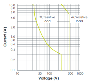
Maximum switching capacity curves :
Operate / release time : 7 / 3 ms typ.
Dielectric strength
• Between open contacts : 1000 VAC (RMS)
• Between contact and coil : 5000 VAC (RMS)
S
Insulation resistance : 1000 MΩ min. (at 500 VDC, 50% relative humidity (RH))
Mechanical life : >1 × 10⁷ operations
Electrical life : >1 × 10⁵ operations (at 8 A, 250 VAC)
When used in a VM600Mk2 slimline rack (ABE056) with a DC power supply, the relay contacts on an IOC4Mk2
module have a maximum switching voltage of 70 VDC / 33 VAC (RMS) (46.7 VAC (PEAK)).
Environmental
Temperature
-
 Jaquet Relay card (Auxiliary module) FTV 3090 377Z-03985
 -
 Jaquet Trip Chain Control card FTBU 3034 377Z-05030
 -
 Jaquet with input card -E04 FTFU 3024 -E04 377Z-05855
 -
 Jaquet with input card -E03 FTFU 3024- E03 377Z-03983
 -
 Jaquet FTFU 3024- E02 377Z-03982 with input card -E02
 -
 Jaquet FTFU 3024-E01 377Z-03981 with input card -E01
 -
 Hirschmann RS20-2400T1T1SDAE Industrial Managed Ethernet Switch
 -
 Hirschmann BELDEN EAGLE30-04022O6TT999SCCV9HSE3F
 -
 Hirschmann MM3-2FXS2/2TX MICE Media Module
 -
 Hirschmann RS20-1600M2M2SDAPHC08.0.05 Industrial Managed Switch
 -
 Hirschmann OZD Profi 12M G12-1300 PRO Fieldbus Repeater
 -
 Hirschmann SPIDER 4TX/1FX-ST EEC Industrial Ethernet Switch
 -
 Hirschmann MM2-2FXM3/2TX1 MICE Media Module
 -
 Hirschmann RS20-2400M2M2SDAPHC09.0.14 Industrial Switch
 -
 Hirschmann RS20-0400M2M2SDAEHC07.1.05 OpenRail Switch
 -
 Hirschmann OZD Profi 12M G12-EEC Fieldbus Repeater
 -
 HIRSCHMANN MDA422-1/2-3.5c-23/46 sensor
 -
Hirschmann RS30-2402T1T1SDAUHC Managed Industrial Switch
-
 Hirschmann OZD GENIUS G12 Industrial Switche
 -
 Hirschmann OZD 485 G12-1300 PRO Fieldbus Repeater
 -
 Hirschmann MM2-2FXM2 MICE Media Module
 -
 Hirschmann RS20-1600S2T1SDAUHC Managed Industrial Switch
 -
 Hirschmann MS20-0800SAAEHH04.2.04 MICE Switch
 -
 Hirschmann SPIDER 4TX/1FX EEC Unmanaged Industrial Switch
 -
 HIRSCHMANN MS4128-L3P EEC Managed Industrial Ethernet Switch
 -
 HIRSCHMANN RS20-0400M2T1SDAPHC08.0.01 Managed Switch
 -
 ETEL EA-S0M-400-40/80A-0000-00 AccurET Modular Power Supply
 -
 ETEL EA-B0I-0-0-0000-00 Backplane Interface Board
 -
 ETEL EA-P2M-400-15/40A-0100-00 Position Controller
 -
ETEL EA-P2M-400-15/40A-0000-00 Position Controller
-
 ETEL EA-P2M-400-10/20A-0100-01 Position Controller
 -
 ETEL EA-P2M-400-10/20A-0000-01 Position Controller
 -
 ETEL EA-P2M-400-5/10A-0100-01 Position Controller
 -
 ETEL EA-P2M-048-2.5/5A-0000-01 Modular Position Controller
 -
 ETEL EA-S0M-300-40/80A-0000-00 Power Supply Module
 -
 ETEL EA-P2M-300-07/15A-0100-01 Position Controller
 -
 ETEL EA-P2M-300-07/15A-0000-01: Modular Position Controller
 -
 ETEL EA-P2M-300-4/7.5A-0100-01 Overview
 -
 Basler Electric MOC2. Motor Operated Potentiometer
 -
 Basler Electric BE1-11 RTD Module, Resistance Temperature Detector
 -
 Basler Electric RDP-110C, Remote Display Panel
 -
 Basler Electric VRM-2020. Voltage Regulation Module
 -
 Basler Electric IDP-1500. Interactive Display Panel
 -
 Basler Electric AEM-2020. Analog Expansion Module
 -
 Basler Electric IDP-2020. Interactive Display Panel
 -
 Basler Electric CEM-2020. Contact Expansion Module
 -
 Basler Electric CEM-125. Contact Expansion Module
 -
 Basler Electric BE2000E, Digital Voltage Regulator
 -
 Basler Electric SMC-150. Synchronous Motor Controller
 -
 Basler Electric AVC125-10. Voltage Regulator
 -
 Basler Electric BE1-25. Sync-Check Relay
 -
 Basler Electric DGC-2020ES, Digital Genset Controller
 -
 ETEL EA-P2M-400-5/10A-0000-01 Position Controller
 -
 Basler Electric BE1-64F, Ground Fault Relay
 -
 Basler Electric BE1-79M, Multi Shot Reclosing Relay
 -
 Basler Electric BE1-81O/U, Digital Frequency Relay
 -
 Basler Electric BE1-87B, High Impedance Bus Differential Relay
 -
 Basler Electric BE1-79A, Reclosing Relay
 -
 Basler Electric BE1-27. BE1-59. BE1-27/59. Voltage Relay
 -
 Basler Electric SMC-250. Synchronous Motor Controller
 -
 Basler Electric SGC-250N, Synchronous Generator Controller
 -
 Basler Electric SGC-250. Synchronous Generator Controller
 -
 Basler Electric BE1-50/51 Plug and Play and Retrofit Relays
 -
 Basler Electric DECS-2100. Digital Excitation Control System
 -
 Basler Electric DECS-250E, Digital Excitation Control System
 -
 Basler Electric BE1-700V, Voltage Only Digital Protective Relay
 -
 Basler Electric DECS-250. Digital Excitation Control System
 -
 Basler Electric DECS-450. Digital Excitation Control System
 -
 Basler Electric DECS-150. Digital Excitation Control System
 -
 Basler Electric ES-49. Temperature Relay
 -
 Basler Electric ES-81O/U, ES-81O,ES-81U Overfrequency Relay
 -
Basler Electric ES-74V, DC Voltage Sensing Relay
-
Basler Electric ES-27/59. Under/Overvoltage Relay
-
 Basler Electric ES-27. Undervoltage Relay
 -
 Basler Electric ES-25. Sync-Check Relay
 -
 Basler Electric ES-47, ES-47N Phase Sequence Relay
 -
Basler Electric ES-37.ES-37/51 Undercurrent Relay
-
 Basler Electric ES-32. Reverse Power Relay
 -
Basler Electric ES-59. Overvoltage Relay
-
 Basler Electric ES-55. Power Factor Relay
 -
 Basler Electric DGC-2020HD, Digital Genset Controller
 -
 Basler Electric BE1-FLEX, Protection, Automation, and Control System
 -
 Schneider GUTOR OC0935 Power Factor Sampling Board
 -
 Schneider GUTOR OC0922 Analog Signal Isolation Board
 -
 Schneider GUTOR OC0908 Battery Voltage Detection Board
 -
Schneider GUTOR OC0947 Temperature / IGBT Sampling Board
-
 Schneider GUTOR OP2601 Communication Expansion Board
 -
 Schneider Electric GUTOR OP2312 bypass control board
 -
 Schneider Electric GUTOR OP2130 Cooling Fan Monitoring & Control Board
 -
 Schneider Electric GUTOR OP2010 Battery Test Board / Battery Management Diagnostic Card
 -
Schneider Electric GUTOR OP2552 Three-phase Power Connection Board Assembly
-
 Schneider Electric GUTOR OP1922A Parallel Control Board / Load-Sharing Synchronization Module
 -
 Schneider Electric GUTOR OP6290B Inverter Feedback Acquisition Board / Signal Scaling Module
 -
Schneider GUTOR OP6280 Basic Signal Board
-
Schneider Electric GUTOR OP2456 / OP2456B Main control board
-
 Schneider Electric GUTOR OP2452 Power Plug-in Panel
 -
 Schneider Electric GUTOR OP2450 Parallel Communication Board
 -
Schneider Electric GUTOR OP2406 Interface Fuse Monitoring Board
-
 Schneider Electric GUTOR OC0919 High-Power Semiconductor Module
 -
 Schneider Electric GUTOR OP6281A System Logic Interface Board
 -
 Schneider Electric GUTOR OP6285A Power Signal Acquisition Board
 -
 Schneider Electric GUTOR OP2438 Fan Monitor & Drive Protection Board
 -
Schneider Electric GUTOR OP2446 Main Control CPU Board
-
 ROLLS-ROYCE CE05-00 Steering Gear Control Module
 -
 ROLLS-ROYCE MARINE AS-BRATTVAAG WRC1021A CONTROLLER CARD
 -
ROLLS ROYCE DECK MACHINERY MPC-300-A7029099 TERMINAL CONTROLLER UNIT
-
 ROLLS-ROYCE HELICON THRUSTER CONTROL PANEL LF90S-01-06
 -
 Rolls-Royce PCC1030C Panel Controller Card
 -
 Rolls-Royce RRDIO15 Remote Digital Input/Output Module
 -
 Rolls-Royce TDI-11 Pitch & Direction Indicator Module
 -
 Rolls-Royce CCN 01 CANman Controller Network Module
 -
 Rolls-Royce SLIO 01 CANman Controller Network Module
 -
 Rolls-Royce MPC-210 Winch & Propulsion Control Module
 -
Rolls-Royce MTI-144 Engine Control Module
-
 Rolls-Royce Tenfjord FB10-002 Steering Gear Module (E-4500-40-1)
 -
 ROLLS ROYCE MARINE AS CIRCUIT BOARD (PCB) RRAI016
 -
 Rolls-Royce Marine AS PIP6-1 Marine Controller
 -
 ROLLS-ROYCE MPC-300 STARTER CONTROL UNIT A7029099
 -
 Rolls-Royce Data Respons MPCF1-10.4" Maritime Panel Computer
 -
 ROLLS-ROYCE MARINE OLC-40009 PCB CARD
 -
Rolls-Royce Marine Brattvaag WRC1021B Controller Board
-
 ROLLS-ROYCE CCN 01 & ROLLS-ROYCE SLIO 02 CANMAN CONTROLLER NETWORK
 -
.png) ROLLS-ROYCE ATC-3-A7033172 AQUAMASTER TURNING CONTROLLER
ROLLS-ROYCE ATC-3-A7033172 AQUAMASTER TURNING CONTROLLER -
 ROLLS-ROYCE POSCON V.3 JOYSTICK MODULE 6459
 -
.png) Rolls-Royce Marine 389-496-00 Joystick Remote Control Panel 6799-W, 389-996-00
Rolls-Royce Marine 389-496-00 Joystick Remote Control Panel 6799-W, 389-996-00 -
 Rolls-Royce data respons 10.4'' Panel Computer 98H010A0000I/R10I53S
 -
 Rolls-Royce H1127.0101 Marine Controller 000068308
 -
 Rolls-Royce CU40-0106-50 Steering Gear Control Panel


