
ABB ACV 700 Frequency Converters
Jumper settings on SNAT 602 TAC: The jumper settings have no effect when the terminal block board is used with the APC.
Code: 3AFE 61041320 Bare panel Code: 3AFE 61068171 Incl. APC 700 PPW board
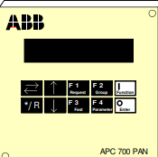
The control panel provides the following information and functions: - Status information (run, ready, fault messages)
- Operational control with 4 freely programmable pushbuttons - Display of reference values (speed, torque) - Display
of actual values (speed, voltage, current) - Display of fault logger contents - Uploading, downloading, changing, displaying
and saving the APC and DDC parameters. It can be used to control up to four DDCs one by one, depending on the application
program. Panel functions are freely programmable. The 9 VDC external power is supplied by the door panel Power Supply Board
APC 700 PPW. Dimensions of the panel are (w x h x d) 125 x 120 x 20 mm. Code: 3AFE 61064770 The door panel power supply
board is used to create the 9 VDC auxiliary voltage needed for the APC 700 PAN. The board is connected directly to the door panel
phone jack type connector by means of a male/male connecting piece. The board needs external 24 VDC power supply. Max.
current is 200 mA. A shielded signal cable from the APC is connected to connector X1. If the solution has several door panels
with one APC, the signal cable can be distributed from connector X1 to connector X1 on the next power supply board. The
The board is a general purpose I/O-board for connecting field signals to APC. It can be used as an extended or remote I/O-board.
The terminal board is always needed with the board because connection to the board is made with a ribbon cable. When the boa
rd is used as an extended I/O-board, it is slid into the CDC board rack and a 64-pole parallel bus connector X1 on the YPQ 111A s
lides into the CDC board rack bus connector. APC board is connected in the same way with the connector X8 to the parallel bus. Th
e 24 VDC power supply for the board is delivered by the parallel bus flat cable. Power consumption is 5 VA (0.2 A at 24 VDC). Peak
current with starting condition is 4 A. When the board is used as a remote I/O-board, it can be mounted anywhere and it is connec
ted to the YPP 110A via the low speed serial bus (RS-485). This configuration needs an external 24 VDC power supply and it is pow
ered via the connection card. Although the address for the board can be set to 0 - F (hex) with switch S1, the system software use
s only addresses 1 - 4 (hex) for the extended I/O-board. Because of this, only 4 extended I/O-boards can be connected to one APC.
Field signals can be connected to the YPQ 111A board via the YPT 111A or YPT 111B connection card. If no extra qualities for input
s and outputs are needeed, YPQ 111A can be used with the connection card UT86-2X40C
The Extended I/O Terminal Board YPT111A is used together with the Extended I/O Board YPQ111A. The Extended I/O Terminal YPT111A is connected to the Extended I/O Board YPQ111A with two 40-pin flat cables. Connection card YPT 111A is used for connecting the field instruments to YPQ111A. There are two separated power supply inputs for 24 VDC in the I/O terminal board YPT111A: +24V IN / BI for binary inputs (X1: pins 1,3,5,7) and +24V IN for YPQ111A when it is used as remote I/O (X1: pins 9,11,13,15). For chaining these voltage inputs from one YPT111A to another YPT111A or YPT111B there are 4 inputs for both the supplies. In the case of chaining one to three 24 VDC inputs will be used as outputs. Pins 9, 11, 13 and 15 of connector X1 should never be used if the I/O board YPQ111A is used as local I/O. The YPQ111A is then connected to the Application Controller YPP110A via the parallel back plane I/O connector and not via the serial bus
APC is designed to give a flexible, compact and efficient system for controlling AC- and DC-drives. APC is programmed by using function blocks. APC can be supplied with unstable + 24 VDC voltage (connector X1) that can vary in the range 19 - 30 VDC. Maximum input power consumption is 15 VA (0.63 A at 24 VDC). This power consumption includes 2 optional communication boards. APC can handle power supply failure with max. duration of 5 ms (i.e. voltage is below 19 V). When the APC board is slid into the CDC board rack, a 64 pole parallel bus (connector X8) on APC slides into the CDC board rack bus connector. AdvantFieldBus 100 (AF 100) is a high speed serial bus (connector X6), which is used for communication between APCs or between an APC and an overriding system such as ABB's MasterPiece 90. The communication board YPK 112A is used to connect the APC to the AF 100. RS-485 bus, a 8 pole screw terminal connector X2, is a low speed serial bus, which is used to connect remote I/O devices and control panels to the APC. Also other APCs can be connected to each other via this bus. The bus has to be grounded at one point to the same ground as the APC. Maximum length of the bus is 300 m. PC-Link, a standard 9 pole female D-connector X4, can be used to connect a personal computer to the APC. Physical interface is a standard non isolated RS-232C (V24) without any handshaking signals. Recommended maximum length of the cable between APC and PC is 5 m. Drive link, an optic link, is used to connect the APC to an AC or a DC drive. Optical fibres are connected to receiver V32 and transmitter V33. Communication speed is 1.5 Mbps. Max. length of the fibre is 15 m with standard attenuation cable (Hewlett-Packard HFBR-R or equivalent) and 25 m with extra low attenuation cable (HewlettPackard HFBR-E or equivalent). For standard I/O signals there is a 26-pole ribbon cable, connector X3, on APC. A separate terminal block board SNAT 602 TAC is always needed for field signal connections. The ribbon cable should be made as short as possible. Unshielded ribbon cable can be used provided that the cable is not longer than 2 m.
-
 Beckhoff Polaris CP7011-1002-0010 operator operator HMI display 30.5 cm
 -
 Beckhoff AM8052-0JH1-0000 Servomotor 10.7 Nm (M0), F5 (104 mm)
 -
 Beckhoff BX5100-0000 CANopen Bus Terminal Controller
 -
 Beckhoff CX9020-0115 PLC Module CX90200115
 -
 Beckhoff module EJ7211-0010 EtherCAT plug-in module
 -
 BECKHOFF AX5203-0000 Servo Driver
 -
 BECKHOFF CP6201-0001-0020 24VDC UNMP
 -
 Beckhoff CX5120-0135 Embedded PC CPU Module
 -
 BECKHOFF C5240-0020/000224115 Plc Module
 -
 Beckhoff CP2918-0000 nelCP29xx-0000Pa | Multi-touch built-in Control Panel with DVI/USB Extended interface
 -
 Beckhoff CX2020-0122 Embedded PC Controller
 -
 Beckhoff C6640-0040 Control Cabinet Industrial PC 7-Slot
 -
 BECKHOFF CONTROL CABINET INDUSTRIAL PC - C6930-1062-0050
 -
 Beckhoff Automation EtherCAT Terminal EK1100 EK1122
 -
Beckhoff CP6533-0001-0060 IPC
-
 Beckhoff EK9500 | EtherNet/IP™ Bus Coupler
 -
 Beckhoff CP6202-1047-0050 - An industrial-grade embedded panel computer.
 -
 Beckhoff C6650-0040 Industrial PC
 -
 BECKHOFF CX5230-0185 / 000119805 PLC Module
 -
 BECKHOFF EL4732 | EtherCAT Terminal, 2-channel analog output, voltage, ±10 V, 16 bit, oversampling
 -
 Beckhoff CP6202-0001-0010 Economy Built-In Panel
 -
 Beckhoff AX5206-0000-0202 Digital Compact Servo Drives 2-channel
 -
 Beckhoff CP6606-0001-0020 7-inch Economy Panel PC
 -
 Beckhoff CPU basic module CX2020-0155 + power supply module CX2100-0004
 -
 Beckhoff CP2913-000 Multi-Touch Display
 -
 Beckhoff CP6500-1012-0060 14250369 Control Cabinet
 -
 Beckhoff CP7902-0001-0000 Economy Control Panel with DVI/USB Extended interface
 -
 Beckhoff C6920-0010 Control cabinet Industrial PC
 -
 BECKHOFF C3640-0050 Build-in Industrial PCs
 -
 Beckhoff KL6023-0000 KL6023 EnOcean Wireless-Adapter
 -
 Kollmorgen AKM54G-ANC2DB00 servo motor
 -
 Kollmorgen AKD-P00606-NBCN-0000 Servo Drive
 -
Kollmorgen S200 Series S20350-VTS SERVO DRIVE
-
 KOLLMORGEN AKD-P00606-NBCC-I000 SERVO DRIVE
 -
 Kollmorgen MV65WKS-CE310/22PB Servo Drive Control Module
 -
 Kollmorgen S20360-VTS-021 Servo Drive
 -
 KOLLMORGEN CR06550 High-precision digital servo amplifier
 -
 KOLLMORGEN DBL5N01050-03S-VV0-S40 3-Phase AC Synchronous Brushless Servo Motor
 -
 KOLLMORGEN S70301-NANANA-024 SERVO DRIVE
 -
 Kollmorgen S20360-VTS S200 Series Servo Drive
 -
 Kollmorgen RBE-03011-A00 Brushless Frameless Servo Motor
 -
 KOLLMORGEN AKD-T00306-NBAN-0000 INPUT SERVO DRIVE
 -
 KOLLMORGEN S700 Servo Controller S70302-NANANA
 -
 Kollmorgen AKD-P00607-NBEC-0000 400/480VAC 4.40KVA Servo Drive.
 -
 KOLLMORGEN S70102-NANANA SERVO DRIVE
 -
 KOLLMORGEN AKM21E-ANSNEH02 PM Servo Motor & PRD-AMPE25EB-00 Servo Drive Array
 -
 KollMorgen SC1R06260 Servo Drive 1.4/2.2 KVA 115230 Vac
 -
 Kollmorgen AKD-P00306-NBAN-0000 Servo Drive
 -
Kollmorgen TTB2-2042-3052-A DC Motor Industrial Drive 5.5A 185 oz/in
-
 KOLLMORGEN SERVOSTAR 610-AS SERVO AMPLIFIER_SERVOSTAR610AS_S61001
 -
 KOLLMORGEN PRD-0016400P-10 & PRD-0016600D-30 Axis Control System Modules
 -
KOLLMORGEN Seidel DBL5N01700-03S-000-S40 Servo Motor
-
 Hirschmann RS20-1600M2T1SDAEHH03.1.02 Rail Switch
 -
 Hirschmann BRS30-24TX Industrial Rail Switch
 -
 Hirschmann RSPM20-4T14T1EV9HHS999.9.99 Managed Ethernet Switch
 -
 Hirschmann BELDEN RS40-0009CCCCSDAPHH09.0.14 / RS400009CCCCSDAPHH09014
 -
Hirschmann RS40 Rail Switch RS40-0009CCCCSDAE
-
 Hirschmann BELDEN RS30-0802T1T1SDAP / RS300802T1T1SDAP Fully Managed Layer 2 Compact Rail Switch
 -
 Hirschmann BELDEN RS20-0800M2M2SDAUHH / RS200800M2M2SDAUHH
 -
 Hirschmann EAGLE30-04022O6TT999SCCY9HSE3F Industrial Firewall Router Switch
 -
 Hirschmann RS20-1600T1T1SDAEHH09.0.14 RS20 Rail Mount Ethernet Switch
 -
 Hirschmann EAGLE0200T1T1TDDY90000HHE05.3.03 Industrial Security Router
 -
Hirschmann - BELDEN MIPP-AD-1L9P
-
 HIRSCHMANN RSPM20-4Z64Z6TV9HHS9 942 106-999 RAIL SAFETY SWITCH
 -
 HIRSCHMANN FIBEROPTIC MODULE FIP P/N: OZDFIPG3T
 -
 HIRSCHMANN RS20-1600M2M2SDAUHH Ethernet rack-mounted switch
 -
 HIRSCHMANN BELDEN RS20-0400T1T1SDAEHH04.0.01 / RS200400T1T1SDAEHH04001
 -
HIRSCHMANN MM2-4FXM3 MICE Media Module
-
HIRSCHMANN RS20-0800M2M2SDAE Industrial Ethernet Rail Switch
-
 Hirschmann RS20-2400T1T1SDAP / RS20-2400T1T1SDAPHH05.0.02
 -
 GE MLJ1005B010H00C MLJ Digital Synchromism Check
 -
 ALSTOM MICROTECH DX21-M2 Digital Excitation Controller
 -
HIRSCHMANN BRS20-1200ZZZZ-STCY99HHSES
-
 HIRSCHMANN MM3-4FXM2 MICE Media Module
 -
Hirschmann RSB20-0800T1T1SAABHH 8Port ENet Rail Switch RSB20
-
 Hirschmann MACH102-8TP Ethernet Switch
 -
 SAACKE DDZ-M marine steam pressure atomizer
 -
 SAACKE SKV-A marine rotary cup atomizer
 -
 SAACKE Seavis HMI05e
 -
 Kollmorgen MMC-SD-2.0-230 Servo Drive 100-240VAC 2KW 10A Output 3PH 100-240VAC
 -
 Kollmorgen Servo drive CR10550
 -
 Kollmorgen AKD-P01207-NACN-0054 Servo Driver
 -
 Kollmorgen S406M-CA-036 Servostar
 -
.png) Kollmorgen AKD-B02407-NAAN-0000 Digital Servo Drive
Kollmorgen AKD-B02407-NAAN-0000 Digital Servo Drive -
 Kollmorgen SERVOSTAR S406AM-CA Digital Servo Drive
 -
 KOLLMORGEN SERVOSTAR 603-AS SERVO AMPLIFIER_SERVOSTAR603AS_S60301
 -
Kollmorgen S700 Servo Controller (S70602-NANANA-NA)
-
 Kollmorgen MPK411 controller
 -
 KOLLMORGEN MMC-SD-1.3-460-D Smart Drive
 -
 KOLLMORGEN AKM21C-CKB2AA-00 / AKM21CCKB2AA00 Servomotor
 -
 BECKHOFF AX5106-0000-0200 | Digital Compact Servo Drives 1-channel
 -
 BECKHOFF C3620-0000 INDUSTRIAL COMPUTER (MOTORSHELVES)
 -
 Beckhoff EK1960-0000 TwinSAFE Compact Controller
 -
 Beckhoff C6930-0050 Control Cabinet Industrial PC
 -
 Beckhoff CP7711-0001-0030 Industrial Computer Detection
 -
 Beckhoff CX1001-0111 Embedded PC CPU Module
 -
 Beckhoff C6017-0020 | Ultra-compact Industrial PC
 -
 Beckhoff EK1322 | 2-port EtherCAT P junction with feed-in
 -
 Beckhoff CP2219-0010 Panel
 -
 BECKHOFF C6015-0020 ULTRA COMPACT INDUSTRIAL PC
 -
 BECKHOFF CX2030-0120/Standard CPU Module Embedded PC Windows PLC controller
 -
 Beckhoff CP7721-1090-0020 Panel PC
 -
 Beckhoff PC CPU Module CX5130-0175
 -
 Beckhoff C6920-0050 Control Cabinet
 -
 Beckhoff EL6631 EtherCAT 2-Port Communication Interface, Profinet RT Controller
 -
 Beckhoff CP6202-0001-0060 touch screen panel PC
 -
 Beckhoff CP3916-1002-0000 Multi-Touch Control Panel
 -
 Beckhoff EP1809-0021 | EtherCAT Box, 16-channel digital input, 24 V DC, 3 ms, M8Preferred type
 -
 Beckhoff CX8190 PLC Embedded Industrial PC Ethernet Controller
 -
 Beckhoff CX2100-0914 Power Supply for External
 -
 Beckhoff Automation CP6906-0001-0000 HMI
 -
 Beckhoff EP7342-0002 Module
 -
 Beckhoff CX1020-0112 / CX1100-0910 / CX1020-N010 / CX1100-0003 Windows CPU
 -
 Beckhoff EP7211-0034 EtherCAT Box 1 Channel Motion Interface
 -
 Beckhoff C6240-0030 Control cabinet Industrial PC
 -
 beckhoff motherboard CB1052-0004 CB1052-0004
 -
 Beckhoff AX2006-AS Servo Drive / Variable Frequency Drive
 -
BECKHOFF CP6207-0001-0020 NSMP
-
 Beckhoff C6930-1142-0060 Industrial Computer
 -
 Beckhoff FC7501-0000 interface card
 -
 Beckhoff CX5140-0175 Embedded PC PLC CPU CX5140 Industrial Controller
 -
 Beckhoff CP7802-1100-0010: High-End IP65 Control Panel with DVI/USB Extended Interface
 -
BECKHOFF CP3716-1058-0010 CONTROL PANEL
-
 Beckhoff AX8108-0000 Single-Axis Module
 -
 Beckhoff CU8851-0000 | USB extension, USB Extended 2.0 receiver box
 -
Beckhoff C6017-0030 | Ultra-compact Industrial PC
-
 Beckhoff CX1001-0120/CX10010120.cx1000-n001.cx1000-n000 System Overview
 -
 Beckhoff CPU Module CX5140-0155/4GB CPU Module


