
Advant Controller 31 Series 40 and 50
1 Introduction
This chapter gives you an introduction to the AC31 automation, from the overall architecture to
the operational rules of the 40 and 50 series basic units
1.1 General information on the AC31 system
The AC31 system consists of the series 30, 40, 50, and 90. This operating manual describes the series 40 and 50.
The AC31 brings accessibility to beginners and experienced automation users alike, for any application with 14 to
approximately 1000 inputs / outputs and more, using the same set of basic components. From a compact machine
fitted with a few automated functions to large installations spread over hundreds of meter, and even kilometers, th
e AC31 can fit your requirements. It is therefore possible to realize distributed applications throughout a site, a wor
kshop, or a machine where each component (input / output units, basic unit) is close to the sensors / actuators. T
he whole setup is connected by a single twisted pair over which all information from the sensors is sent after proc
essing by the basic unit to the actuators via the remote modules. Additional central units configured as slave can
also be connected to this CS31 system bus. In case of the series 40 and 50 the following communication interface
s are available, to extend the AC31’s possibilities and integration with the company's other automation systems: M
ODBUS, ASCII, ARCNET, RCOM, AF100. The developments in this field are continua
Many users on all the continents have realized numerous applications such as:
Machine control:
- Manufacturing of floor boards
- Assembly of electrical contactors
- Manufacturing of ceramic products
Controlling-commanding installations:
- Wharf cranes
- Water treatment
- Ski lifts
- Wind power machines, etc.
System management:
- Climatic anagement
- Building power management
- Tunnel ventilation
- Alarms in hospital environments
- Greenhouse lighting / humidity, etc.
1.2 General set-up rules
An ABB AC31 system always includes at least one
AC31 basic unit. There are three types of basic un
its: - The 40 series basic unit, with a local interface
for central inputs / outputs extensions - The 50 ser
ies basic unit, with a local interface for central inpu
ts / outputs extensions and a CS31 system bus inter
face for decentralized extensions - The 90 series basi
c unit, with a CS31 system bus interface for decentrali
zed extensions Each basic unit incorporates a specific
number of digital inputs/outputs and in case of the
series 90 occasionally analog inputs/outputs. It is po
ssible, depending on the basic unit, to increase the
number of inputs / outputs, to add input / output e
xtensions connected directly to the basic units or re
mote input / output units via the CS31 twisted pair.
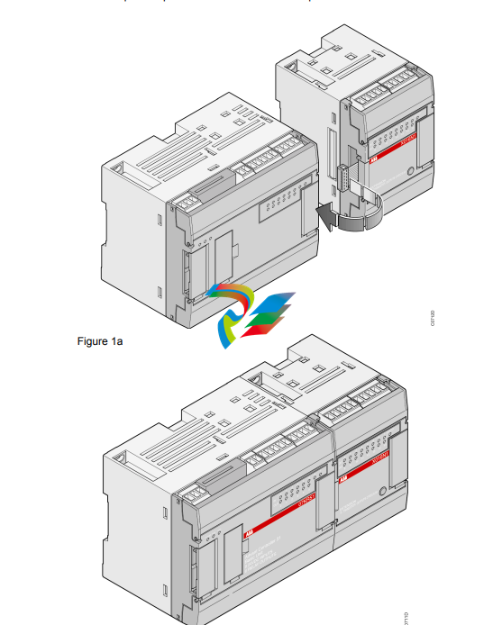
A master basic unit can manage up to 31 connection points, such as: - Series 50
remote units with central extension possibilities: a maximum of 6 extension units
comprising of e. g. a maximum of 8 analog input channels and 8 analog output c
hannels - Series 30 and 90 remote unit (without central extension possibilities) wi
th analog or digital inputs / outputs - An ABB NCSA-01 variable speed drive interfa
ce - A high-speed counter unit - 30, 50 and 90 series basic units as slave with the
ir own user program - Or any other device which supports CS31 communication. C
omment: A connection point fitted solely with digital channels occupies 1 connecti
on point. A connection point fitted with digital and analog channels occupies 2 con
nection points of the available 31. The maximum number of remote analog units d
epends on the MASTER basic unit: - 50 series: - a maximum of 31 remote analog i
nput units or - a maximum of 31 remote analog output units or - a maximum of 15
central extensible remote units (ICMK 14 ..) with analog input/output extensions +
1 remote analog input/output unit (15 x 2 + 1 = 31) or - a mixed digital/analog co
nfiguration within the previous limits - 90 series: - a maximum of 12 remote analog
input units or - a maximum of 12 remote analog output units or - a maximum of 1
2 central extensible remote units with analog extensions or - a mixed digital/analog
configuration within the permissible limits
1.3 Power cuts or drops, battery
The 40 and 50 series basic units provide an incorporated battery buffer in order
to save the necessary information for the next startup should there be a power
drop or cut. The buffer battery is an usual in the trade Vanadium Lithium accum
ulator. It is soldered on a printed-circuit board inside the unit and qualified perso
nnel can exchange it by themselves. The accumulator is 100 % charged after 1
2 operating hours without interruption. Its lifetime is between 6 and 15 years; it
depends on how often and how long the power supply of the unit is switched off.
The battery buffer time is 20 days at 25 °C. During that time data (e.g. flags) can
be stored with power supply of the unit switched off. The status word %IW 1062
.15 (EW 62,15), Bit 3 gives information on the status of the battery (0 correspond
s to error, 1 corresponds to OK). Caution: The following operating instructions are t
o be observed: • Never short-circuit or operate battery with the polarities reversed!
They are likely to overheat and explode. Avoid chance short circuiting and therefor
e do not store batteries in metal containers and do not place them on metallic surfa
ces. Escaping lithium is health hazard. • Replace battery only with power supply on.
Otherwise data may be lost. • Dispose of battery environmentally consciously! To sa
ve all or part of the data prior configuration of the basic unit is required (refer to volu
me 2 - System Technology). If the configuration of the basic unit is absent then all f
unctions and internal data will be reset to 0 after power cut.
3.1.3 Earthing 3.1.3.1 Basic earthing principles Use rigid wires or multi-con
ductor wires AWG 14 (1.95 mm2 ) or bigger diameter. The earth and mains
wires should be connected in star. All AC31 components of a cabinet shou
ld be connected to the same earth. When the remote units are situated ou
tside the cabinet they should be connected to the nearest earth. The 40 an
d 50 series basic units are fitted with an earth plate with the DIN rail mount
ing system. Also, if the basic unit is screwed directly to a metal plate, the sc
rew located at the top left of the basic unit (as seen from the front) ensures
an electrical connection to the earth via the earth plate. This earthing ensur
es protection against electromagnetic disturbances. The safety earthing cabl
e (on terminal block) should be connected to the cabinet chassis. 3.1.3.2 Ea
rthing principles for several cabinets When the cabinets are close to each oth
er the different earths should be connected together using a cable with a cro
ss section of at least 16 mm² (see Figure 3- on page 4-3). The noise genera
ting devices (actuators, motors, etc.) should not be earthed in-between two
. The earthing should be done near to the element causing the most disturb
ance (see Figure 3-2).
-
 AEROTECH SM Series High-Performance Stepper Motors
 -
 AEROTECH BLMSC Series Linear Motors
 -
 AEROTECH Custom Linear Motors
 -
 AEROTECH BMS Series Brushless, Slotless Rotary Motors
 -
 AEROTECH BM Series Brushless Rotary Motors
 -
 AEROTECH BLMX Series Linear Motors
 -
 AEROTECH BLMH Series Linear Motors
 -
 AEROTECH BLM Series Linear Motors
 -
 AEROTECH BLMC Series Linear Motors
 -
 AEROTECH BLMUC-143 Linear motor forcer with thermistor
 -
AEROTECH BLMUC-111 Linear motor forcer with thermistor
-
AEROTECH BLMUC-95 Linear motor forcer with thermistor
-
AEROTECH BLMUC-79 Linear motor forcer with thermistor
-
AEROTECH BLMUC Series Linear Motors
-
 AEROTECH Automation1 FLEX Distributed Amplifier Multi-Axis Servo Control System
 -
 AEROTECH Automation1 HXA4 6-Axis Hexapod Servo Drive
 -
 AEROTECH Automation1 iHXA4 6-Axis Hexapod Servo Drive with Motion Controller
 -
 AEROTECH Modular System Control Console
 -
 AEROTECH TV Series Transformers
 -
 AEROTECH TM Series Transformers
 -
 AEROTECH UFM Noise Filter Module
 -
 AEROTECH MFM Motor Filter Module
 -
 AEROTECH MPG Handwheel Pendant
 -
 AEROTECH Automation1 Multi-Axis Joystick
 -
 AEROTECH ETM Enhanced Throughput Module
 -
 AEROTECH Automation1 XL4s High-Speed, Single-Phase Linear Servo Drive
 -
 AEROTECH Automation1 XL2e Enhanced, Compact Linear Servo Drive
 -
 Automation1 iXL2e Enhanced, Compact Linear Servo Drive with Motion Controller
 -
 AEROTECH Automation1 XL5e Enhanced, Linear Servo Drive
 -
 AEROTECH Automation1 iXL5e Enhanced Linear Servo Drive with Motion Controller
 -
 AEROTECH Automation1 GI4 Laser Scan Head Controller
 -
 AEROTECH Automation1 SI4 Stepper Interface
 -
AEROTECH Automation1 XI4 Servo Interface
-
 AEROTECH AEROTECH Automation1 iXI4 Servo Interface with Motion Controller
 -
 AEROTECH Automation1 XC6e Enhanced, High-Power PWM Servo Drive
 -
 AEROTECH Automation1 iXC6e Enhanced, High-Power PWM Servo Drive with Motion Controller
 -
 AEROTECH Automation1 XC2 Compact PWM Servo Drive
 -
 AEROTECH Automation1 XC4 PWM Servo Drive
 -
 AEROTECH Automation1 GL4 Galvo Laser Scan Head Linear Drive
 -
 AEROTECH Automation1 XC2e Enhanced, Compact Servo Drive with PWM+
 -
 AEROTECH Automation1 XC4e Enhanced, PWM Servo Drive
 -
 AEROTECH Automation1 XR3 Multi-Axis Servo Drive Rack
 -
 AEROTECH Automation1 iXR3 Multi-Axis Servo Drive Rack with Motion Controller
 -
 AEROTECH Automation1 iXC2 Compact PWM Servo Drive with Motion Controller
 -
 AEROTECH Automation1 iXC2e Enhanced, Compact PWM+ Servo Drive with Motion Controller
 -
 AEROTECH Automation1 iXC4 PWM Servo Drive with Motion Controller
 -
 AEROTECH Automation1 iXC4e Enhanced, PWM Servo Drive with Motion Controller
 -
 AEROTECH Automation1 iPC Industrial PC with Motion Controller
 -
 AEROTECH EPICS & TANGO Drivers for Distributed Control Systems
 -
 AEROTECH .NET, C, Python & LabVIEW APIs Custom Application Develotpmen
 -
 AEROTECH Automation1 Industrial Ethernet Support
 -
 AEROTECH Automation1 iSMC Intelligent, Software-Based Motion Controller
 -
 AEROTECH Automation1 iXA4 1- 2- or 4-Axis PWM Servo Drive with Motion Controller
 -
 AEROTECH Automation1 XA4 1- 2- or 4-Axis PWM Servo Drive
 -
 CTI 2500-ADP2-DISC Discrete Wiring Adapter for Series 500
 -
 CTI 2500-ADP1 Analog Wiring Adapter for Series 500
 -
 CTI 2500C-RADP-RS485 Remote Base Controller Adapter for Series 500
 -
 CTI 2500C-RADP-RBC Profibus RBC Adapter for Series 500
 -
 CTI 2500C-PADP-120V 120VAC 50W Power Supply for Series 500
 -
 CTI 2500-RADP RBC Adapter for Series 500
 -
 CTI 2500-R4500 520/530/DBC Adapter for Series 500 - MATURE
 -
 CTI 2500-PADP Power Supply Adapter for Series 500
 -
 CTI 2500-IADP I/O Adapter for Series 500
 -
 CTI 2500-VP15A-N4-W7 15" Flat-Panel PC with Windows® 7 Embedded
 -
 CTI 2500S-27-1750 Slice I/O, Ethernet, RS232/485. 900MHz, 2DIO / 4UAI / 2AI
 -
 CTI 2500S-26-1750 Slice I/O, Ethernet, RS232/485. 900MHz, 8DIO / 2UAI
 -
 CTI 2500S-23-1750 Slice I/O, Ethernet, RS232/485. 900MHz, 4DI / 4DO / 2UAI / 2AO
 -
 CTI 2500S-27-1550 Slice I/O, RS232/485. 2DIO / 4UAI / 2AI
 -
 CTI 2500S-26-1550 Slice I/O, RS232/485. 8DIO / 2UAI
 -
 CTI 2500S-23-1550 Slice I/O, RS232/485. 4DI / 4DO / 2UAI / 2AO
 -
 CTI 2500S-27-1050 Slice I/O, Ethernet, 2DIO / 4UAI / 2AI
 -
 CTI 2500S-26-1050 Slice I/O, Ethernet, 8DIO / 2UAI
 -
 CTI 2500S-23-1050 Slice I/O, Ethernet, 4DI / 4DO / 2UAI / 2AO
 -
 CTI 2500C-32F-CJC 32-Pin Field Wiring Connector with Cold Junction Compensation
 -
 CTI 2500C-32F 32-Pin Field Wiring Connector
 -
 CTI 2500C-8-TC Eight Thermocouple Inputs
 -
 CTI 2500C-8-RTD Eight RTD Inputs
 -
 CTI 2500C-8-RL-FC 8 Form-C Relay Outputs
 -
 CTI 2500C-8-IDO-24V 8 Isolated 24VDC Outputs
 -
 CTI 2500C-8-IDO-120V 8 Isolated 120VAC Outputs
 -
 CTI 2500C-16-DO-24V Sixteen 24VDC Digital Outputs
 -
 CTI 2500C-16-DO-120V Sixteen 120VAC Digital Outputs
 -
.png) CTI 500C-16-IDI-24V Sixteen Isolated 24V AC/DC Digital Inputs
CTI 500C-16-IDI-24V Sixteen Isolated 24V AC/DC Digital Inputs -
 CTI 2500C-16-IDI-120V Sixteen Isolated 120V AC/DC Digital Inputs
 -
 CTI 2500C-16-DIDO-SIM Sixteen Digital Input and Output SImulator
 -
 CTI 2500C-16-DI-24V Sixteen 24V AC/DC Digital Inputs
 -
 CTI 2500C-16-DI-120V Sixteen 120V AC/DC Digital Inputs
 -
 CTI 2500C-RBC-RS485 RS485 Remote Base Controller
 -
 CTI 2500C-RBC-PRF Profibus Remote Base Controller
 -
 CTI 2500C-PS-24V-35 35-Watt DC Power Supply
 -
 CTI 2500C-PS-120V-35 35-Watt AC Power Supply
 -
 CTI 2500C-R8 Eight-Slot Base
 -
 CTI 2500C-R4 Four-Slot Base
 -
 CTI 2500C-R16 Sixteen-Slot Base
 -
 CTI 2500C-2572-B Fast Ethernet TCP/IP Adapter
 -
 CTI 2500C-J750 Compact Janus PAC with 3MB Project Memory
 -
 CTI 2500C-C300 CPU with 512K User Memory
 -
 CTI 2500C-C200 CPU with 256K User Memory
 -
 CTI 2500C-C100 CPU with 128K User Memory
 -
 CTI 2500C-8-AO 8 Analog Outputs
 -
 CTI 2500C-8-AI 8 Analog Inputs
 -
 CTI 2559-FCAL Precision Calibration Connector
 -
 CTI 2559-FPC 40-Position Screw-Terminal Connector
 -
 CTI 2500-RFC PLC to RF Modem Cable
 -
 CTI 2500-40F 40-Position Standard Screw-Terminal Connector
 -
 CTI 2505 Vibration Sensor Interface Module
 -
 CTI 2554-A 4-Channel Isolated High Speed Counter Module
 -
 CTI 2553-A 2-Channel Mag Meter Input Module
 -
 CTI 2502 2-Channel High Speed Counter Input Module
 -
 CTI 2559-TC 8-Channel Thermocouple Input Module
 -
 CTI 2556-A 16-Channel Isolated Thermocouple Input Module
 -
 CTI 2556 16-Channel Isolated Thermocouple Input Module
 -
 CTI 2551-A 8-Channel Isolated Thermocouple Input Module
 -
 CTI 2559-RTD 8-Channel RTD Input Module
 -
 CTI 2557-A 16-Channel RTD Input Module
 -
 CTI 2557 16-Channel RTD Input Module
 -
 CTI 2552-A 8-Channel Isolated RTD Input Module
 -
 CTI 2534 8-Point Form-C Relay Output Module
 -
 CTI 2532 16-Point Form-A Relay Output Module
 -
 CTI 2531 32-Point Form-A Relay Output Module
 -
 CTI 2530 8-Point Form-C Relay Output Module
 -
 CTI 2562 8-Channel Analog Output Module
 -
 CTI 2560-A 8-Channel Isolated Analog Output Module
 -
 CTI 2501 8in/4out Analog Module
 -
 CTI 2558 8-Channel Analog Input Module
 -
 CTI 2555-A 16-Channel Analog Input Module
 -
 CTI 2550-A 8-Channel Isolated Analog Input Module
 -
 CTI 2599 8/16/32-Point AC Output Module


