
Allied TelesisLayer 2 Ethernet Switch
This guide contains the hardware installation instructions for the AT-8000S/16, AT-8000S/24, AT-8000S/24POE, AT-8000S/48 and AT-8000S/48POE Fast Ethernet Switches.
How This Guide is Organized
This manual contains the following chapters
• Chapter 1 Product Description describes the features and components of the switches.
• Chapter 2 Installation describes the installation instructions for the switches.
• Chapter 3 Stacking describes the stacking instructions for the switches.
• Chapter 4 Initial Configuration describes the instructions for initially configuring the switches.
• Chapter 5 Troubleshooting provides information on how to resolve problems that might occur with the switches.
• Appendix A Technical Specifications contain the technical specifications for the switches.
• Appendix B Translated Safety Standards contain the safety standards for the device.
Document Conventions
This document uses the following conventions to highlight important information:
Contacting Allied Telesis This section provides Allied Telesis contact information for technical support as well as sales or corporate information.
Online Support
You can request technical support online by accessing the Allied Telesis Knowledge Base from the following web site: www.alliedtelesis.com/kb. You can use the Knowledge Base to submit questions to our technical support staff and review answers to previously asked questions.
Email and Telephone Support
For Technical Support via email or telephone, refer to the Allied Telesis web site: www.alliedtelesis.com. Select your country from the list displayed on the website. Then select the appropriate menu tab..
Returning Products
Products for return or repair must first be assigned a Return Materials Authorization (RMA) number. A product sent to Allied Telesis without a RMA number will be returned to the sender at the sender’s expense. To obtain an RMA number, contact the Allied Telesis Technical Support group at our web site: www.alliedtelesis.com/support/rma. Select your country from the list displayed on the website. Then select the appropriate menu tab..
For Sales or Corporate Information
You can contact Allied Telesis for sales or corporate information at our web site: www.alliedtelesyn.com. Select your country from the list displayed on the website. Then select the appropriate menu tab..
Warranty
The AT-8000S has a limited warranty of lifetime (two years PSU and fan). Go to www.alliedtelesis.com/warranty for the specific terms and conditions of the warranty and for warranty registration.
The new AT-8000S series combines the best of the previous L2 series; stackability and affordability. The new AT-8000S series is an entry level managed switch for the SMB, Small Office/Field Office offering managed desktop connectivity. The fiber uplink provides connectivity between workgroups over a larger distances. In addition the AT-8000S series is also equipped with a copper 10/100/1000Base-T port for connectivity to gigabit aggregation switches
The new AT-8000S series combines value with the necessary management features for networked applications. There are five device models which provide different hardware configurations and include the following:
• AT-8000S/16 device which supports 16 built-in 10/100Base-T ports, and a Combo port functionality that supports both copper and SFP interfaces. • AT-8000S/24 device with stacking ports which supports 24 built-in 10/100Base-T ports, two Gigabit stackable and 2 Combo Ports, inclusive of a Combo port functionality that supports both copper and SFP interface. • AT-8000S/24POE device with stacking port which supports 24 built-in 10/100Base-T ports, two Gigabit stackable and 2 Combo Ports, inclusive of a Combo port that supports both copper and SFP interface. The PoE function is supported on RJ-45 ports. • AT-8000S/48 device with stacking ports which supports 48 built-in 10/100Base-T ports, two Gigabit stackable and 2 Combo Ports, inclusive of a Combo port functionality that supports both copper and SFP interface. • AT-8000S/48POE device with stacking port which supports 48 built-in 10/100Base-T ports, two Gigabit stackable and 2 Combo Ports, inclusive of a Combo port that supports both copper and SFP interface. The PoE function is supported on RJ-45 ports
The AT-8000S/24, AT-8000S/24POE, AT-8000S/48 and AT-8000S/48POE can be joined together into a stack of up to six units. For more information, see Chapter 3 Stacking. Device configuration is performed through an Embedded Web Server (EWS) or through a Command Line Interface (CLI). The device management is performed through a DB-9 RS-232 interface.
Features The AT-8000S/16, AT-8000S/24, AT-8000S/24POE, AT-8000S/48 and AT-8000S/48POE features include the following:
• Wirespeed switching traffic across all ports
• Auto MDI/MDIX enabled
• 802.1d, 1w, 1s priority tags supported
• Broadcast storm control
• IEEE 802.1Q tagged VLANs supported • GARP/GVRP supported
• Port/MAC based VLANs supported • 802.3ad link aggregation Static and Dynamic (LACP) supported
• IEEE 802.1P based QoS supported
• Ingress rate limiting
• Egress rate shaping (WRR)
• 802.1x port/MAC based authentication support
• RFC 2618 RADIUS Authentication • SSL/ SSLv3
• RFC 1492 TACACS+ • Management ACL support
• Industry standard CLI
• Browser based management interface (HTTP)
• Telnet access supported
• SNMP v1, v2 and v3
• RFC1757 RMON support
• Port Mirroring support
• PVE • Port Security
• DHCP support
• Static IP Multicast support
• IGMP Snooping
IEEE Standards
– IEEE 802.3
— 10Base-T
– IEEE 802.3u
— 100Base-TX
– IEEE 802.3ab
— 1000Base-TX Gigabit Ethernet
– IEEE 802.3z
— Full Duplex
– IEEE 802.3u
— Auto-Negotiation
– IEEE 802.3x
— Flow Control, Symmetric and Asymmetric
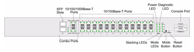
The AT-8000S/16 front panel is configured as follows:
• 16 10/100Mbps Ports — RJ-45 ports designated as 10/100Base-T. The RJ-45 ports are designated as ports Ports 1 - 16.
• 1 10/100/1000Base-T Copper Port — There is one copper 10/100/100Base-T port designated on the switch as port 17R. This port is paired with the SFP slot designated on the switch as port 17. Together these two ports form the Combo ports shown in Figure 1.
• 1 SFP Port — There is one SFP slot supports either a 100Base-FX or a 1000Base-X (fiber) connection and is designated on the switch as port 17. This SFP slot is paired with the 10/100/1000Base-T copper port which is designated on the switch as port 17R. Together these two ports form the Combo ports shown in Figure 1.
• DB-9 Console port — An asynchronous serial console port supporting the RS-232 electrical specification. The port is used to connect the device to the console managing the device.
• Reset Button — Button to reset the device.
• Mode Button — Selects the port LED indications.
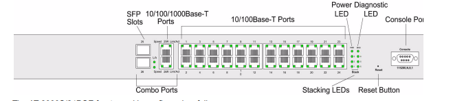
AT-8000S/24 Front Panel
The AT-8000S/24 front panel is configured as follows:
• 24 10/100Mbps Ports — RJ-45 ports designated as 10/100Base-T. The RJ-45 ports are designated as ports Ports 1 - 24.
• 2 10/100/1000Base-T Copper Ports — There are two copper 10/100/100Base-T ports designated on the switch as ports 25R and 26R. These ports are paired with the two SFP slots designated on the switch as ports 25 and 26. Together these four ports form the Combo ports shown in Figure 3..
• 2 SFP Ports— There are two SFP slots which support either a 100Base-FX or a 1000Base-X (fiber) connection and are designated on the switch as ports 25 and 26. This SFP slot is paired with the two 10/100/ 1000Base-T copper ports which is designated on the switch as port 25R and 26R. Together these four ports form the Combo ports shown in Figure 3.
• DB-9 Console port — An asynchronous serial console port supporting the RS-232 electrical specification. The port is used to connect the device to the console managing the device.
• Reset Button — Button to reset the device.
• Mode Button — Selects the port LED indications.
AT-8000S/24POE Front Panel
The AT-8000S/24POE front panel is configured as follows:
• 24 10/100Mbps Ports — RJ-45 ports designated as 10/100Base-T. The RJ-45 ports are designated as ports Ports 1 - 24.
• 2 10/100/1000Base-T Copper Ports — There are two copper 10/100/100Base-T ports designated on the switch as ports 25R and 26R. These ports are paired with the two SFP slots designated on the switch as ports 25 and 26. Together these four ports form the Combo ports shown in Figure 5..
• 2 SFP Ports— There are two SFP slots which support either a 100Base-FX or a 1000Base-X (fiber) connection and are designated on the switch as ports 25 and 26. This SFP slot is paired with the two 10/100/ 1000Base-T copper ports which is designated on the switch as port 25R and 26R. Together these four ports form the Combo ports shown in Figure 5.
• DB-9 Console port — An asynchronous serial console port supporting the RS-232 electrical specification. The port is used to connect the device to the console managing the device.
• Reset Button — Button to reset the device.
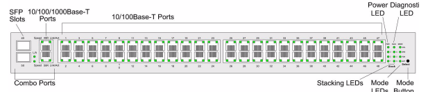
The AT-8000S/48 device front panel is configured as follows:
• 48 10/100Mbps Ports — RJ-45 ports designated as 10/100Base-T. The RJ-45 ports are designated as ports Ports 1 - 48.
• 2 10/100/1000Base-T Copper Ports — There are two copper 10/100/100Base-T ports designated on the switch as ports 49R and 50R. These ports are paired with the two SFP slots designated on the switch as ports 49 and 50. Together these four ports form the Combo ports shown in Figure 7..
• 2 SFP Ports — There are two SFP slots which support either a 100Base-FX or a 1000Base-X (fiber) connection and are designated on the switch as ports 49 and 50. This SFP slot is paired with the two 10/100/ 1000Base-T copper ports which is designated on the switch as port 49R and 50R. Together these four ports form the Combo ports shown in Figure 7.
• Mode Button — Selects the port LED indications.
This section contains information for installing the device, and includes the following sections:
• Preparing for Installation
• Installing the Device
• Connecting the Device
• Rack Installation
Preparing for Installation
This section provides an explanation for preparing the installation site, and includes the following topics:
• Preparing for Installation
• Site Requirements
• Unpacking
Package Contents While unpacking the device, ensure that the following items are included:
• One AT- 8000S/xx series unit
• Rubber Feet for desktop installation
• Rack-mount kit hardware accessories
• An AC power cable
• Stacking cable (Yellow color)
• Console RS-232 cable with DB-9 connector
• Installation guide on CD
• Warranty and registration card
To unpack the device perform the following: 1. It is recommended to put on an ESD wrist strap and attach the ESD clip to a metal surface to act as ground. An ESD strap is not supplied with the device. 2. Place the container on a clean flat surface and cut all straps securing the container. 3. Open the container. 4. Carefully remove the device from the container and place it on a secure and clean surface. 5. Remove all packing material. 6. Inspect the product for damage. Report any damage immediately. If any item is found missing or damaged, please contact your local ATI reseller for a replacement.
Installing the Device
The device can be installed on a flat surface or mounted in a rack. This section includes the following topics:
• Desktop or Shelf Installation
• Rack Installation
Desktop or Shelf Installation
When installing the switch on a desktop or shelf, the rubber feet included with the device should first be attached. Attach these cushioning feet on the bottom at each corner of the device. Ensure the surface is be able to support the weight of the device and the device cables. To install the device on a surface, perform the following: 1. Attach the rubber feet on the bottom of the device. The following figure illustrates the rubber feet installation on the device.
-
 Hirschmann RS20-1600M2T1SDAEHH03.1.02 Rail Switch
 -
 Hirschmann BRS30-24TX Industrial Rail Switch
 -
 Hirschmann RSPM20-4T14T1EV9HHS999.9.99 Managed Ethernet Switch
 -
 Hirschmann BELDEN RS40-0009CCCCSDAPHH09.0.14 / RS400009CCCCSDAPHH09014
 -
Hirschmann RS40 Rail Switch RS40-0009CCCCSDAE
-
 Hirschmann BELDEN RS30-0802T1T1SDAP / RS300802T1T1SDAP Fully Managed Layer 2 Compact Rail Switch
 -
 Hirschmann BELDEN RS20-0800M2M2SDAUHH / RS200800M2M2SDAUHH
 -
 Hirschmann EAGLE30-04022O6TT999SCCY9HSE3F Industrial Firewall Router Switch
 -
 Hirschmann RS20-1600T1T1SDAEHH09.0.14 RS20 Rail Mount Ethernet Switch
 -
 Hirschmann EAGLE0200T1T1TDDY90000HHE05.3.03 Industrial Security Router
 -
Hirschmann - BELDEN MIPP-AD-1L9P
-
 HIRSCHMANN RSPM20-4Z64Z6TV9HHS9 942 106-999 RAIL SAFETY SWITCH
 -
 HIRSCHMANN FIBEROPTIC MODULE FIP P/N: OZDFIPG3T
 -
 HIRSCHMANN RS20-1600M2M2SDAUHH Ethernet rack-mounted switch
 -
 HIRSCHMANN BELDEN RS20-0400T1T1SDAEHH04.0.01 / RS200400T1T1SDAEHH04001
 -
HIRSCHMANN MM2-4FXM3 MICE Media Module
-
HIRSCHMANN RS20-0800M2M2SDAE Industrial Ethernet Rail Switch
-
 Hirschmann RS20-2400T1T1SDAP / RS20-2400T1T1SDAPHH05.0.02
 -
 GE MLJ1005B010H00C MLJ Digital Synchromism Check
 -
 ALSTOM MICROTECH DX21-M2 Digital Excitation Controller
 -
HIRSCHMANN BRS20-1200ZZZZ-STCY99HHSES
-
 HIRSCHMANN MM3-4FXM2 MICE Media Module
 -
Hirschmann RSB20-0800T1T1SAABHH 8Port ENet Rail Switch RSB20
-
 Hirschmann MACH102-8TP Ethernet Switch
 -
 SAACKE DDZ-M marine steam pressure atomizer
 -
 SAACKE SKV-A marine rotary cup atomizer
 -
 SAACKE Seavis HMI05e
 -
 Kollmorgen MMC-SD-2.0-230 Servo Drive 100-240VAC 2KW 10A Output 3PH 100-240VAC
 -
 Kollmorgen Servo drive CR10550
 -
 Kollmorgen AKD-P01207-NACN-0054 Servo Driver
 -
 Kollmorgen S406M-CA-036 Servostar
 -
.png) Kollmorgen AKD-B02407-NAAN-0000 Digital Servo Drive
Kollmorgen AKD-B02407-NAAN-0000 Digital Servo Drive -
 Kollmorgen SERVOSTAR S406AM-CA Digital Servo Drive
 -
 KOLLMORGEN SERVOSTAR 603-AS SERVO AMPLIFIER_SERVOSTAR603AS_S60301
 -
Kollmorgen S700 Servo Controller (S70602-NANANA-NA)
-
 Kollmorgen MPK411 controller
 -
 KOLLMORGEN MMC-SD-1.3-460-D Smart Drive
 -
 KOLLMORGEN AKM21C-CKB2AA-00 / AKM21CCKB2AA00 Servomotor
 -
 BECKHOFF AX5106-0000-0200 | Digital Compact Servo Drives 1-channel
 -
 BECKHOFF C3620-0000 INDUSTRIAL COMPUTER (MOTORSHELVES)
 -
 Beckhoff EK1960-0000 TwinSAFE Compact Controller
 -
 Beckhoff C6930-0050 Control Cabinet Industrial PC
 -
 Beckhoff CP7711-0001-0030 Industrial Computer Detection
 -
 Beckhoff CX1001-0111 Embedded PC CPU Module
 -
 Beckhoff C6017-0020 | Ultra-compact Industrial PC
 -
 Beckhoff EK1322 | 2-port EtherCAT P junction with feed-in
 -
 Beckhoff CP2219-0010 Panel
 -
 BECKHOFF C6015-0020 ULTRA COMPACT INDUSTRIAL PC
 -
 BECKHOFF CX2030-0120/Standard CPU Module Embedded PC Windows PLC controller
 -
 Beckhoff CP7721-1090-0020 Panel PC
 -
 Beckhoff PC CPU Module CX5130-0175
 -
 Beckhoff C6920-0050 Control Cabinet
 -
 Beckhoff EL6631 EtherCAT 2-Port Communication Interface, Profinet RT Controller
 -
 Beckhoff CP6202-0001-0060 touch screen panel PC
 -
 Beckhoff CP3916-1002-0000 Multi-Touch Control Panel
 -
 Beckhoff EP1809-0021 | EtherCAT Box, 16-channel digital input, 24 V DC, 3 ms, M8Preferred type
 -
 Beckhoff CX8190 PLC Embedded Industrial PC Ethernet Controller
 -
 Beckhoff CX2100-0914 Power Supply for External
 -
 Beckhoff Automation CP6906-0001-0000 HMI
 -
 Beckhoff EP7342-0002 Module
 -
 Beckhoff CX1020-0112 / CX1100-0910 / CX1020-N010 / CX1100-0003 Windows CPU
 -
 Beckhoff EP7211-0034 EtherCAT Box 1 Channel Motion Interface
 -
 Beckhoff C6240-0030 Control cabinet Industrial PC
 -
 beckhoff motherboard CB1052-0004 CB1052-0004
 -
 Beckhoff AX2006-AS Servo Drive / Variable Frequency Drive
 -
BECKHOFF CP6207-0001-0020 NSMP
-
 Beckhoff C6930-1142-0060 Industrial Computer
 -
 Beckhoff FC7501-0000 interface card
 -
 Beckhoff CX5140-0175 Embedded PC PLC CPU CX5140 Industrial Controller
 -
 Beckhoff CP7802-1100-0010: High-End IP65 Control Panel with DVI/USB Extended Interface
 -
BECKHOFF CP3716-1058-0010 CONTROL PANEL
-
 Beckhoff AX8108-0000 Single-Axis Module
 -
 Beckhoff CU8851-0000 | USB extension, USB Extended 2.0 receiver box
 -
Beckhoff C6017-0030 | Ultra-compact Industrial PC
-
 Beckhoff CX1001-0120/CX10010120.cx1000-n001.cx1000-n000 System Overview
 -
 Beckhoff CPU Module CX5140-0155/4GB CPU Module
 -
 Beckhoff CP6533-0001-005: Built-in Panel PC with High-Definition Multi-Touch Control
 -
 Beckhoff EL5042 | EtherCAT Terminal, 2-channel encoder interface, BiSS® C
 -
 Beckhoff C6920-1080-0040: Premium Control Cabinet Industrial PC
 -
 Beckhoff C6920-0060 | Control cabinet Industrial PC
 -
 Beckhoff Embedded-PC CX5010-1121
 -
 Beckhoff CB3050-0010 Mainboard Motherboard
 -
 Beckhoff PLC module CX1020-0000 Basic CPU module (service phase)
 -
 Beckhoff CP7812-1056-0010 15" Multitouch Display Control Panel
 -
 Beckhoff CX5120-0115 /2GB Controller Module
 -
 Beckhoff CP7201-1000-0000 Industrial Panel PC
 -
 Beckhoff Servo Motor AM8061-0JH1-0000
 -
 BECKHOFF CP6503-0001-0050 Built-in Panel PC
 -
Beckhoff CP3919-0010 Display G190ETN01.2 19" PCT V04. Multi-touch Control Panel
-
 Beckhoff CX5110-0112-9020/000368201 Embedded PC Intel Atom Processor
 -
 Beckhoff AX8206-0000 Dual-Axis Module
 -
Beckhoff Nail Operating Terminal CP7032-1031-0010
-
Beckhoff AM8042-0EH1-0000 Servomotor 4.10 Nm (M0), F4 (87 mm)
-
 Beckhoff EK9300 Beckhoff CPU Module
 -
Beckhoff CP3224-0020 Multitouch-Panel-PC
-
 Beckhoff CP2712-0000 12.1" 24VDC Touch Screen WMD0
 -
 BECKHOFF CX5240-0195 / 0000289234 Embedded PC 40 GB CFast Card
 -
 Beckhoff CP6932-1000-0000 Control Panel
 -
 BECKHOFF CX5120-0121 PLC Module
 -
 Beckhoff EL3218 | EtherCAT Terminal, 8-channel analog input
 -
Beckhoff C6640-0050 | Control cabinet Industrial PC
-
 Beckhoff Cx5130-0120/4GB Embedded-PC
 -
 BECKHOFF CX2030-0122 PLC PROCESSOR
 -
 BECKHOFF CX5020-0122 Controller Module
 -
 Beckhoff CP3915-0000 Multitouch Panel
 -
 BECKHOFF EL3014 | EtherCAT Terminal
 -
 BECKHOFF Industrial Computer c6920-1057-0030
 -
 Beckhoff CX5130-0141/4GB CX5130-0141 Embedded PC
 -
 Beckhoff C6240-1052-0040 4-086-06-3073 Industrial Computer
 -
 Beckhoff CX5140-0135 /4GB High-Performance Embedded Industrial PC
 -
 Beckhoff C6515-1001-0000 Industrial PC
 -
 Beckhoff AX5103-0000-0200 - Digital Compact Servo Drives
 -
 Beckhoff CX2030-0130-1003/4GB Basic CPU module
 -
 Beckhoff AX8620-0000 Power Supply Module
 -
 Beckhoff CX9020-0111 module with
 -
 Beckhoff EL7332 PLC Module
 -
 BECKHOFF CP7709-0001-0020 HMI
 -
 Beckhoff CX5120-0155/2GB Embedded PC
 -
 BECKHOFF CP7037-1037-0010 OPERATOR INTERFACE TOUCHSCREEN
 -
 Beckhoff EK9000 | ModbusTCP/UDP Bus Coupler
 -
 Beckhoff Touch Panel Screen CP6020 -0000-0000
 -
 Beckhoff CX2020-0121 Module FAST Shipping
 -
 Beckhoff CX2030-0125 Basic CPU Module
 -
 Beckhoff CP3918-0000 Multi-Touch 18.5" Control Panel
 -
 Automotion LC4A00010 DC BL Motor Control, ATS, Sub Assy, SCP, 115VAC,
 -
 500T-115VAC - VAS ENGINEERING - DORIC 500 SERIES DIGITAL TEMP INDICATOR
 -
 Honeywell X-DCS2000/EN Digital Integrated System Manager 50/60Hz 100-240V #4
 -
 Kollmorgen S60600 Servostar600 606-Fan 4 kVA, 6 A, 3 X 230 - 480 V


