
MOOGUser Manual M3000® Automation System MSC II (Moog Servo Controller)
1 General Information
1.1 About this Manual
This manual is valid only for the M3000 About this Manual ® automation system and M3000®
modules. It contains most important instructions that must be observed in order to operate the M3000® automation system and M3000® modules in a
safe manner.
Every person responsible for machinery planning, mounting, and operation
must read, understand, and follow all points covered in this manual. This applies especially to the safety instructions. Following the safety instructions
helps to avoid accidents, faults, and material damage!
Using M3000® Safely
(Prerequisites)
The following items must be observed as fundamental elements of safety
when using the M3000® automation system and M3000® modules:
• All safety instructions contained in this manual
• All safety instructions contained in the documentation of the M3000®
modules
• All safety instructions contained in the product related hardware and
software documentation required for the relevant application
• All relevant nationally and internationally applicable safety and accident
prevention regulations and standards
1.1.1 Reservation of Changes and Validity
Reservation of Changes
and Validity for this
Manual
The information contained in this manual is valid at the time of this version's
release. See footer for version number and release date of this manual.
Moog reserves the right to make changes to this manual at any time without
specified reasons.
1.1.2 Exclusion of Liability
This manual was prepared with great care and the contents reflect the authors' best knowledge. However, the possibility of error remains and improvements are possible.
Please feel free to submit any comments regarding errors or incomplete information to Moog.
Exclusion of Liability for
this Manual
Moog does not offer any guarantee that the contents conform to applicable
legal regulations nor does Moog accept any liability for incorrect or incomplete information and the consequences thereof.
1.1.3 Completeness
Completeness of this
Manual
This manual is complete only when used in conjunction with the product related hardware and software documentation required for the relevant application.
1.1.4 Place of Storage
Place of Storage
for this Manual
This manual and all other associated documentation for hardware and software must always be kept in a location where they will be readily accessible
and close to the M3000® automation system and M3000® modules or the
equipment in which they are installed
1.2 Selection and Qualification of Personnel
Only qualified users may work with and on the M3000 Qualified Users ® automation system or M3000® modules.
Qualified users are properly trained experts with the required knowledge and
experience. In particular, these experts must have the authorization to bring
into operation, ground, and label devices, systems, and power circuits in accordance with safety engineering standards. Those people working on a
project must be familiar with safety concepts common in automation.
1.3 Proper Use
The M3000 Proper Use ® modular automation system is suitable for control applications in
the medium to high end performance ranges.
M3000® is designed for use within the overvoltage category defined by
IEC 60364-4-44 for controlling machines and industrial processes in low voltage systems in which the rated supply voltage does not exceed 1,000 V alternating current (50/60 Hz) or 1,500 V direct current.
Qualified project planning and design, proper transportation, storage, installation, and use are required to ensure fault-free, reliable, and safe operation of
M3000®.
M3000® and M3000® modules must not be brought into operation until it has
been ensured that the equipment in which they are installed complies with the
current version of the EU machinery directive.
The M3000® automation system and M3000® modules may be used only under the conditions and situations specified in this manual and in the documentation of the M3000® modules.
Any other or more extensive use is not permissible.
The following are also required for proper use:
• Compliance with the requirements detailed in this manual
• Compliance with the requirements of individual M3000® module documentation
• Compliance with all of the product related hardware and software documentation required for the relevant application
• Compliance with the relevant nationally and internationally applicable
regulations, standards, and directives, e.g., the regulations specified by
a professional organization, such as TÜV or VDE
1.3.1 Safety Related Systems
Safety Related Systems
Special measures are required to use control technology in safety related
systems.
When planning to use control technology in a safety related system, the user
should seek detailed advice in addition to any available standards or guidelines for safety installations.
WARNING As with any electronic automation system, the failure of
certain components when using M3000® or M3000® modules might lead to an uncontrolled and/or unpredictable
operational condition. The user should take into consideration the system level effects of all types of failures
and implement corresponding safety measures.
1.4 Warranty and Liability
Moog's standard delivery and payment conditions apply. The owner/operator
will have access to these by the time the contract is closed at the latest.
Exclusion of Warranty and
Liability
Warranty and liability claims for personal and material damage will be excluded when they are the result of the following, among others:
• Improper use of the M3000® automation system or M3000® modules
Ö-"1.3-Proper Use" on page 2
• Use of the M3000® automation system or M3000® modules
in a technically imperfect condition
• Use of the M3000® automation system or M3000® modules
by unqualified users
Ö-"1.2-Selection and Qualification of Personnel" on page 2
• Failure to comply with this manual, the documentation of the
M3000®-modules, or the product related hardware and software
documentation required for the relevant application
• Failure to comply with the relevant nationally and internationally
applicable regulations such as the regulations of a professional
association, the TÜV, or the VDE
• Improper deployment of the M3000® automation system or
M3000®-modules, such as in a potentially explosive, excessively
warm, or excessively cold environment
• Improper storage, transportation, mounting, removing, connection,
bringing into operation, operation, cleaning, or maintenance of the
M3000® automation system or M3000® modules
• Storage or transportation of M3000® modules or accessories
outside of the original packaging
Ö-"9-Transportation and Storage" on page 71
• Unauthorized or improperly executed structural changes to the
M3000® automation system or M3000® modules
• Unauthorized or improperly executed repairs on the M3000® automation
system or M3000® modules
Ö-"8.2.2-Repair" on page 70
• Damage due to the intrusion of foreign objects or acts of God.
1.5 Inspection of Delivery
After receiving the delivery, please check the original packaging and its con- Inspection of Delivery
tents for any damage.
If the packaging or contents exhibit any damage, do not bring the items into
operation. In this case, immediately notify Moog or the responsible supplier.
In addition, the packaging should be retained. The packaging might be
needed to enforce damage compensation claims on the transport company.
After taking the delivery, please check whether all items listed on the delivery
docket are present. If anything is missing, immediately notify Moog or the responsible supplier.
Retain the Original
Packaging
It is advisable to retain the original packaging for any future transport or storage needs.
1.6 Environmental Protection
1.6.1 Emissions
Environmental Protection:
Emissions
M3000® modules do not have any harmful emissions when used properly.
1.6.2 Disposal
Environmental Protection:
Disposal
1.7 Standards
1.7.1 CE Labeling of M3000® Modules
CE Labeling of M3000®
Modules
1.7.2 IEC 61131-2
M3000® and M3000®
Modules Comply with
IEC 61131-2
The M3000® automation system and M3000® modules comply with the requirements of IEC 61131-2.
1.7.3 Electromagnetic Compatibility (EMC)
Electromagnetic
Compatibility (EMC)
M3000® modules comply with the requirements and protection targets of the
EU directive 89/336/EEC “Electromagnetic Compatibility” (EMC directive)
and comply with the harmonized European standards (EN) that were published in the Official Journals of the European Union for programmable controllers.
Especially important are the rules for proper EMC wiring in cabinets and
buildings according to IEC 61131-4. Installation in metal, grounded cabinets
is preferred.
M3000® modules are designed for use under normal operating conditions in
industrial environments and comply with the following standards:
• DIN EN 61000-6-2
• DIN EN 61000-6-4
If suitable additional measures are taken, M3000® modules may also be employed in residential, commercial and light-industrial environments in compliance with the following standards:
• DIN EN 61000-6-1
• DIN EN 61000-6-3
Suitable additional measures:
Ö-"4.2-Use in Special Environments" on page 28
The applicable disposal regulations must be observed when disposing of
M3000® modules!
All M3000® modules comply with the standards specified in
their relevant declaration of conformity.
CE labeling of the M3000® modules is based on proper installation of the automation system with proven electromagnetic compatibility (EMC).
Where technical requirements lead to deviations from the standard,
these are specified in this manual or in the documentation of the relevant
M3000® modules
If the system does not comply with the requirements of DIN EN 61000-6-1
and DIN EN 61000-6-3, despite the additional measures, M3000® modules
must not be used in residential, commercial and light-industrial environments.
EMC conformity may be presumed only under the following conditions:
• Sufficient shielding
• Mounting of the DIN rail module onto a DIN top-hat rail that is attached to
an electrically conductive, grounded mounting plate
Ö figure-17 on page 31
MSC II and extension modules must be powered from a power supply with
SELV (Safety Extra-Low Voltage) according to DIN EN 60950-1. Therefore
the EU low voltage directive is not relevant for the M3000® automation system because the specified voltage levels lie below the limits.
1.8 Trademarks
Moog and Moog Authentic Repair are registered trademarks of Moog Inc. Trademarks
and its subsidiaries.
M3000® is a trademark of Moog GmbH that is registered in the EU.
1.9 Software Copyrights
The software that is installed on M3000 Software Copyrights ® products at the time of delivery is
the property of the manufacturer. At the time of delivery, every piece of installed software is covered by copyright protection. It may be reproduced only
with the approval of the manufacturer or in accordance with the license
agreements.
All product and company names mentioned in this manual might be protected trademarks or brands of the relevant manufacturer.
The absence of the symbols ® or ™ does not indicate that the name is
2 Safety Instructions
This chapter summarizes the most important safety instructions. When handling the M3000® automation system or M3000® modules the safety instructions in the other chapters of this manual must be followed as well as the
safety instructions in the product related hardware and software documentation required for the specific application.
Following the safety instructions helps to avoid accidents, faults, and
material damage!
2.1 Typographical Conventions
Safety Instructions:
Typographical
Conventions
The following symbols and styles are used for identifying the different types of
safety instructions:
Additional typographical conventions:
Ö-"12.1-Typographical Conventions" on page 124
2.2 Safety Instructions
2.2.1 Safety Related Systems
Safety Instructions: Safety
Related Systems
More on this subject: Ö-"1.3.1-Safety Related Systems" on page 2
DANGER Identifies safety instructions that are intended to warn of
an immediate and impending danger to life and limb or
major property damage.
Failure to observe these safety instructions will lead inevitably to death, serious personal injury (disablement)
or major property damage!
WARNING Identifies safety instructions that are intended to warn of
potential danger to life and limb or the potential for major property damage.
Failure to observe these safety instructions might lead
to death, serious personal injury (disablement) or major
property damage!
CAUTION Identifies safety instructions that are intended to warn of
slight personal injury or minor property damage.
Failure to observe these safety instructions might lead to
slight personal injury or minor property damage.
As with any electronic automation system, the failure of
certain components when using M3000® or M3000® modules might lead to an uncontrolled and/or unpredictable
operational condition. The user should take into consideration the system level effects of all types of failures
and implement corresponding safety measures
2.2.2 Environmental Conditions
Safety Instructions:
Environmental Conditions
More on this subject:
Ö-"4-Environmental Conditions" on page 27
Ö-"10.2.2-Environmental Conditions" on page 74
2.2.3 ESD
Safety Instructions: ESD
WARNING Maintain under all circumstances the required environmental conditions specified for the M3000® automation
system or M3000® modules.
This ensures fault-free, reliable, and safe operation.
WARNING The PC on which tools such as MACS development environment are installed must be suitable for the environmental conditions in which it will operate.
This ensures fault-free, reliable, and safe operation.
WARNING It is not permissible to operate the M3000® automation
system or M3000® modules in a potentially explosive
environment.
WARNING The M3000® automation system and M3000® modules
must not come into direct contact with liquids, except
where explicitely specified. Danger of short-circuit!
If they do come into direct contact with a liquid, immediately
disconnect the power supply! Before bringing the system
back into operation, it is essential that all affected components are completely dry and have been inspected by a suitably qualified technician.
WARNING Protect the M3000® automation system, M3000® modules, and the license key from electrostatic discharges!
Electrostatic discharges might damage the device's internal
components or delete the device's internal memory.
2.2.4 Project Planning and Installation
Safety Instructions:
Project Planning and
Installation
WARNING The vent holes of M3000® modules facilitate convection
cooling and must never be covered!
Covered vent holes might result in overheating and fire.
WARNING No work of any kind, such as mounting, removing, wiring, or repairs to the M3000® automation system or
M3000® modules may be performed while the automation system or the modules are in operation!
There is a danger of:
• Uncontrolled movements
• Permanent damage
• Malfunctions
Before performing any work on the M3000® automation system or M3000® modules, it is essential that the system is
stopped and the power supply is disconnected.
Therefore, all power supplies must be switched off, including
those from attached peripherals such as externally supplied
transmitters, programming devices, etc.!
WARNING M3000® modules must be protected from overvoltages
and/or reverse energization from the sensor to the module!
There is a danger of:
• Permanent damage by overheating or fire
• Malfunctions
M3000® modules must have the correct voltage, polarity, and
terminal assignments.
WARNING The internal electronics of M3000® modules and attached sensors must be supplied with power from a permanently connected (unswitched) power supply that
cannot be individually switched off, without switching
off the module's power supply.
If a switched power supply is used, such as when there are
intermediate switching devices (emergency stops, manual
operators, etc.), the following problems might arise, depending on the state of the power supply for the internal electronics of the module and sensors (Ö-table-3 on page 41):
• Reverse energization from sensor to module
• Invalid sensor data
WARNING Sensors that are connected to digital inputs of M3000®
modules with several I/O groups, such as MSC I, QDIO,
or RDIO, must under all conditions be supplied from the
same power supply as the corresponding I/O-group to
which the sensor is connected!
Otherwise, if the power supply for the internal electronics of
the module is switched off, there might be reverse energization from the sensor to the module.
There is a danger of:
• Uncontrolled movements
• Fault or failure of a manual control
• Permanent damage to the module
• Malfunctions
Digital I/Os of MSC II and MSD Motion Controller are protected against reverse energization.
More on these subjects:
Ö-"5-Mechanical Installation" on page 29 or
Ö-"6-Project Planning and Installation" on page 37
To avoid damage to M3000® modules or accessories,
cleaning, maintenance, and repair tasks may be performed only by Moog or Moog's authorized service
agents.
Warranty and liability claims for personal and material damage are excluded when, among other reasons, they are due
to unauthorized repairs or other unauthorized interventions.
Ö-"1.4-Warranty and Liability" on page 3
WARNING No work of any kind, such as mounting, removing, wiring, or repairs to the M3000® automation system or
M3000® modules may be performed while the automation system or the modules are in operation!
There is a danger of:
• Uncontrolled movements
• Permanent damage
• Malfunctions
Before performing any work on the M3000® automation system or M3000® modules, it is essential that the system is
stopped and the power supply is disconnected.
Therefore, all power supplies must be switched off, including
those from attached peripherals such as externally supplied
transmitters, programming devices, etc.!
ARNING The M3000® automation system and M3000® modules
must not come into direct contact with liquids, except
where explicitely specified. Danger of short-circuit!
If they do come into direct contact with a liquid, immediately
disconnect the power supply! Before bringing the system
back into operation, it is essential that all affected components are completely dry and have been inspected by a suitably qualified technician.
WARNING If an M3000® module is to be taken out of operation, the
entire system must always be shut down and disconnected from all power supplies.
Therefore, all power supplies must be switched off, including those from attached peripherals such as externally supplied transmitters, programming devices, etc.!
The M3000® module must be protected against unintentional restarting!
If the M3000® module is connected to other devices and/or
facilities, always consider the full consequences and take appropriate precautions before switching off the module.
Maintain, under all circumstances, the required environmental conditions specified for transportation and storage of the M3000® automation system or M3000® modules.
Ö-"9.1-Environmental Conditions" on page 71
This ensures fault-free, reliable, and safe operation.
2.2.7 Communication Between MSC II and MACS
Safety Instructions:
Communication Between
MSC II and MACS
More on this subject:
Ö-"10.5-Programming and Configuration" on page 84
2.2.8 License Key of the MSC II
Safety Instructions:
License Key of the
MSC II
More on this subject: Ö-"10.6-License Key" on page 85
WARNING The MSC II control module's operational state can be altered with the MACS development environment when the
MSC II control module is connected online with MACS.
This can be done by means of the following actions, for example:
• Stopping or resetting the program
• Setting breakpoints
• Activating the single step mode
• Downloading application programs
• Writing or forcing values
Therefore, the operator must always consider the effects and
take appropriate precautions before altering the operational
state of the MSC II control module with MACS.
The license key of the MSC II control module must be
protected from electrostatic discharges!
Electrical discharges might damage the license key or delete
the contents of the license key's memory.
WARNING The license key may be inserted or removed only when
the MSC II control module is powered down!
Attempting to insert or remove the license key during operation might damage the license key or the MSC II control module permanently.
WARNING The license key must always remain inserted while the
MSC II control module is in operation. Otherwise, the
MSC II control module will not work.
If the license key is removed during operation, the application
program will stop after a few minutes. If the MSC II control
module is connected online to the MACS development environment, a corresponding error message will appear in
MACS.
In addition, the digital output 'Outputs Enabled' will be
switched to the 0 state, thereby disabling all of the MSC II
control module's digital outputs and terminating fieldbus communication and E-bus communication.
Ö-"10.17.2-'Outputs Enabled' Output (LED «OutEN»)" on
page 111
After switching off the MSC II control module and inserting
the license key, the MSC II control module can be brought
back into operation
2.2.9 Run/Stop/Reset
Safety Instructions:
Run/Stop/Reset
More on this subject: Ö-"10.7-Run/Stop/Reset Switch" on page 88
2.2.10 Switching Back on or Resetting the MSC II
Safety Instructions:
Switching Back on or
Resetting the MSC II
More on this subject:
Ö-"10.8.1-Behavior at Switching on and Switching off" on page 89
2.2.11 'Outputs Enabled' Output of the MSC II
Safety Instructions:
'Outputs Enabled' Output
of the MSC II
More on this subject:
Ö-"10.17.2-'Outputs Enabled' Output (LED «OutEN»)" on page 111
WARNING If the most recent status in the online mode (MACS
logged in) was 'Run' before the MSC II control module
was switched off or reset, the boot project will always be
started after the MSC II control module is switched back
on or reset.
This will occur regardless of which application program was
previously running.
In other words, the application program that will be started
automatically after the MSC II control module is switched on
or reset might be different from the application program that
was executing immediately prior.
If there is a defect in an output stage, the 'Outputs Enabled' signal will not necessarily shut down all of the
outputs securely
3 Short M3000® System Overview
Short M3000®
System Overview
The M3000® automation system comprises the following hardware and software components:
• MSC II starter kit
Complete package including everything needed to get started with
MSC II
Ö-"3.2-MSC II Starter Kit" on page 15
• M3000® modules
– MSC I (Moog Servo Controller)
Control module for DIN top-hat rail mounting
Ö-"3.3.1-MSC I" on page 16
– MSC II (Moog Servo Controller)
Control module for DIN top-hat rail mounting
Ö-"3.3.2-MSC II" on page 17
– QDIO 16/16
Digital I/O extension module for local extension of the inputs and
outputs of MSC I or MSC II (connection over E-bus)
Ö-"3.3.3.1-QDIO and QAIO" on page 18
– QAIO 2/2
Analog I/O extension module for local extension of the inputs and
outputs of MSC I or MSC II (connection over E-bus)
Ö-"3.3.3.1-QDIO and QAIO" on page 18
– QAIO 16/4
Analog I/O extension module for local extension of the inputs and
outputs of MSC I or MSC II (connection over E-bus)
Ö-"3.3.3.1-QDIO and QAIO" on page 18
– QEBUS-CAN
CAN extension module for MSC II which can be used to make available the LocalCAN bus of an E-bus group for external CAN bus network stations (over a D-sub front panel connector)
Ö-"3.3.3.2-QEBUS-CAN" on page 19
– RDIO
Remote module with digital I/Os and CANopen interface (connection over CAN bus)
Ö-"3.3.4.1-RDIO" on page 20
– RDISP
Display and operating terminal with TIA/EIA 232 and CANopen interface (connection over CAN bus)
Ö-"3.3.4.2-RDISP" on page 20
– DialogController
Displays with TFT technology and touch screen. Programmable
with MACS development environment. Data exchange via Ethernet
with MSC II or MSD Motion Controller.
Ö-"3.3.4.3-DialogController" on page 21
– MSD Motion Controller
Motion control module for MSD Servodrives
Ö-"3.3.5-MSD Motion Controller" on page 22
– MSD Servodrive
Modular Multi-Axis Programmable Motion Control Servodrive
Ö-"3.3.6-MSD Servodrive" on page 23
• License keys
Hardware keys necessary for the operation of the MSC I, MSC II and
MSD Motion Controller.
Ö-"3.4-License Key" on page 24
• MACS (Moog Axis Control Software)
Development environment according to IEC 61131 for solving complex
control tasks
Ö-"3.5-Application Programs" on page 25
• MACS HMI (Moog Axis Control Software Human Machine Interface)
Visualization package which can be run without MACS
Ö-"3.6.1-MACS HMI Visualization Package" on page 26
3.1 M3000® System Architecture
M3000® System
Architecture
The M3000® automation system has the hardware and software structure
necessary for modular and flexible automation solutions with distributed intelligence.
The MSC II control module can use an Ethernet connection (LAN, company Ethernet
network, peer-to-peer connection) to communicate with another controller,
development environment, or visualization package.
Ö-"7.1-Ethernet" on page 47
Ö-"10.5.1-Communication Between MSC II and MACS" on page 84
Ö-"10.5.1.1-Ethernet Communication Interface" on page 84
To create real time capable applications, even in distributed systems and to CAN Bus
give the application a better structure, M3000® can also be divided hierarchically.
Ö-"7.5-CAN Bus and CANopen" on page 55
WideCAN and LocalCAN are two equal, mutually independent CAN bus interfaces. In a typical application they are used as follows:
• WideCAN can be used for networking of individual control groups or re- WideCAN
mote modules. Usually, WideCAN is used for synchronization and data
exchange between the control groups and operating stations of a machine or system.
Ö-"3.3.4-R-Modules (Remote Modules)" on page 19
Ö-"7.7.4-WideCAN Bus Groups" on page 67
In addition, the WideCAN network can integrate other components with
a CAN bus or CANopen interface, such as motor controllers, hydraulic
valves, and radial piston pumps.
• LocalCAN connects the DIN rail modules within a LocalCAN bus group LocalCAN
and, if applicable, the QEBUS-CAN to the connected LocalCAN bus
groups or CAN sensors/actuators.
Ö-"3.3.3.2-QEBUS-CAN" on page 19
Ö-"7.7.3-LocalCAN Bus Groups" on page 66
The M3000® modules mentioned here represent only a part of Moog's
current product range. In addition to other M3000® modules, Moog's
product range includes a large variety of accessories.
Ö-"11-Product Range" on page 114
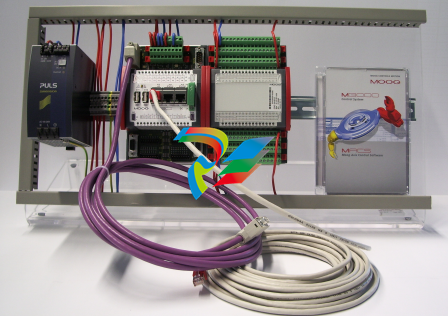
The MSC II starter kit is available in two versions:
• MSC II with Profibus-DP slave
• MSC II with dual EtherCAT master
It includes everything needed to get started:
• MSC II
• Power supply 24 V 10 A
• License key, green
• QDIO 16/16-0,5
• MACS development environment
• Software maintenance contract
• Crossed Ethernet interface cable, 10 m (10.94 yd)
• CAN bus interface cable, 3 m (3.28 yd)
• 6 Plug-in terminal strips with screw terminals, 18 pole
• 2 Plug-in terminal strip with screw terminals, 9 pole
• 4 Plug-in terminal strips with spring power clamp, 10 pole
The included DIN rail modules MSC II and QDIO are mounted (together with
the power supply) on a single mounting plate.
A suitable power cord is the only additional item required to facilitate connection to the power source.
3.3 M3000® Modules
3.3.1 MSC I
MSC I
Figure 2: MSC I Control Module
The MSC I digital control module is a fully programmable multi-axis controller.
The inputs and outputs of the MSC I can be extended locally by attaching
Q-modules. The MSC I and the attached modules then form an E-bus group.
MSC I and Q-modules within E-bus groups communicate over the internal
E-bus.
The MSC I is programmed and configured with the MACS development environment (complies with IEC 61131).
Ö-"3.5-Application Programs" on page 25
The M3000® modules mentioned here represent only a part of Moog's
current product range. In addition to other M3000® modules, Moog's
product range includes a large variety of accessories.
Ö-"11-Product Range" on page 114

3.3.2 MSC II
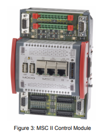
The MSC II digital control module is a fully programmable multi-axis controller.
The inputs and outputs of the MSC II can be extended locally by attaching
Q-modules. The MSC II and the attached modules then form an E-bus group.
MSC IIs and Q-modules within E-bus groups communicate over the internal
E-bus.
Ö-"7.7.2-E-Bus Groups" on page 65
The MSC II is programmed and configured with the MACS development environment (complies with IEC 61131).
Ö-"3.5-Application Programs" on page 25
3.3.3 Q-Modules
Q-Modules are I/O extension modules for MSC I and MSC II. Q-Modules
The following Q-modules are available from Moog:
• QDIO 16/16 (digital I/O extension module)
Ö-"3.3.3.1-QDIO and QAIO" on page 18
• QAIO 2/2 (analog I/O extension module)
Ö-"3.3.3.1-QDIO and QAIO" on page 18
• QAIO 16/4 (analog I/O extension module)
Ö-"3.3.3.1-QDIO and QAIO" on page 18
• QEBUS-CAN (CAN extension module)
Ö-"3.3.3.2-QEBUS-CAN" on page 19
Q-modules can be used only as E-bus slaves within E-bus groups.
Ö-"7.7.2-E-Bus Groups" on page 65
When using an RDIO as E-bus master, only QDIOs can be used as E-bus
slaves.
Ö-"7.6.2.1-E-Bus Master and E-Bus Slaves" on page 61
Detailed information about the MSC II:
Ö-"10-MSC II (Moog Servo Controller)" on page 72
Refer to the Q-modules' documentation for more detailed information
3.3.3.1 QDIO and QAIO
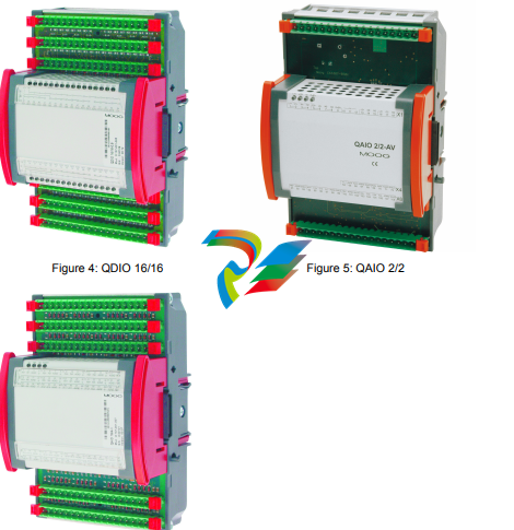
QDIO and QAIO I/O extension modules can be used to locally extend the inputs and outputs of an MSC I or MSC II. They have no internal intelligence.
Instead, the MSC I or MSC II actuates them via I/O operation directly over the
internal E-bus.
QDIO 16/16-0,5 is a digital I/O extension module with 16-digital inputs and QDIO 16/16-0,5
16-individually configurable digital I/Os.
QDIO 16/16-0,5 provides positive switching inputs and I/Os.
QDIO 16/16-0,5N provides zero switching inputs and I/Os.
QAIO 2/2 is an analog I/O extension module with 2 analog inputs (each con- QAIO 2/2
figurable as ±10 V, ±10 mA, 4-20 mA) and 2 analog voltage outputs-(±10 V
additionally each configurable as ±10 mA, 4-20 mA, ±50 mA).
QAIO 16/4 is an analog I/O extension module with 16-analog inputs and QAIO 16/4
4-analog voltage outputs-(±10 V).
QAIO 16/4-V provides 16-voltage inputs (±10 V).
QAIO 16/4-A provides 16-current inputs (0–20 mA).
3.3.3.2 QEBUS-CAN
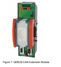
QEBUS-CAN is a CAN extension module which can be used to make the
LocalCAN bus of an E-bus group available for external CAN bus network stations (over a D-sub front panel connector).
3.3.4 R-Modules (Remote Modules)
R-Modules
(Remote Modules)
R-Modules are extension modules with CANopen interface.
The following R-modules are available from Moog:
• RDIO (remote module with digital I/Os and CANopen interface)
Ö-"3.3.4.1-RDIO" on page 20
• RDISP (display and operating terminal)
Ö-"3.3.4.2-RDISP" on page 20
IEC 61131 application programs cannot run on R-modules.
R-modules connect to other network stations over the CAN bus.
Ö-"7.4.1-TIA/EIA 232 Interface Cables" on page 54
Refer to the R-modules' documentation for more detailed information.
3.3.4.1 RDIO

RDIO is a remote module with digital I/Os and CANopen interface. RDIOs
can be parameterized as a CANopen slave according to CiA DS 401.
RDIO 16/16-0,5 provides 16-positive switching digital inputs and 16 positive RDIO 16/16-0,5
switching digital I/Os.
RDIO is a remote module with digital I/Os and CANopen interface. RDIOs
can be parameterized as a CANopen slave according to CiA DS 401.
RDIO 16/16-0,5 provides 16-positive switching digital inputs and 16 positive RDIO 16/16-0,5
switching digital I/Os.
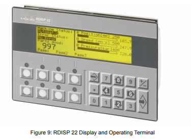
RDISP is a versatile display and operating terminal with TIA/EIA 232 and
CANopen interface as well as a graphical LCD display and function keys
which can be labelled. A slip of paper can be inserted below the keys for labeling purposes.
RDISP 22 provides 22-function keys and a display with max. 8 lines of RDISP 22
40-characters each or random graphics.
Dimensions of RDISP 22:
187 mm × 120 mm × 56 mm (7.36 in × 4.72 in × 2.2 in)
The CPRDISP software (needed to program and configure the RDISP) CPRDISP
is not included with RDISP. CPRDISP is available from Moog as an accessory.
3.3.4.3 DialogController
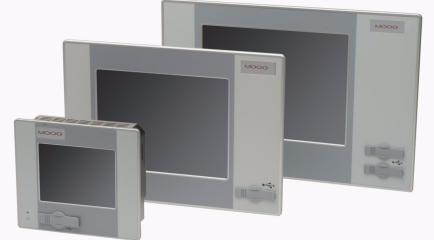
The DialogController is freely programmable with the Moog Axis Control Software (MACS) development environment. The predefined visualization elements such as buttons, bar graphs, meters, tables and histograms makes it
easy to create visualization screens.
In addition it offers TFT technology for brilliant colors, fanless operation,
Ethernet communication for programming and operation.
It is available in three sizes:
• DialogController 5.7 "
Color TFT, ¼ VGA resolution, 320 x 240 pixels with touch screen
Dimensions: W x D x H: 194 x 172 x 52 mm / 7.6 x 6.8 x 2.0 inch
• DialogController 10.4 "
Color TFT, VGA resolution, 640 x 480 pixels with touch screen
Dimensions: W x D x H: 360 x 260 x 77 mm / 14.2 x 10.2 x 3.0 inch
• Display 12.1 "
Color TFT, SVGA resolution, 800 x 600 pixels with touch screen
Dimensions: W x D x H: 440 x 300 x 77 mm / 17.3 x 11.8 x 3.0 inch
-
 HIRSCHMANN MSM20-M2M2M2M2SY9HH9E Ethernet media modul
 -
 HIRSCHMANN SPIDER-PL-20-05T1999999TWVHHHH Industrial Ethernet Rail Switch
 -
 Hirschmann SPIDER-PL-20-07T1M2M299TWVHHHH Industrial ETHERNET Rail Switch
 -
.png) Hirschmann (Belden) RS20-1600M2M2SDAEHC09.1.00 DIN-rail managed industrial Fast Ethernet switch
Hirschmann (Belden) RS20-1600M2M2SDAEHC09.1.00 DIN-rail managed industrial Fast Ethernet switch -
 Hirschmann (Belden) RS30-1602O6O6TDAPHC09.1.00 DIN-rail managed industrial Ethernet switch
 -
 Hirschmann (Belden) RS30-2402O6T1SDAPHH09.0.13 DIN-rail industrial Ethernet switch
 -
Hirschmann (Belden) SPIDER-PL-20-04T1S29999TY9HHHH Ethernet DIN-rail switch
-
 HIRSCHMANN RS20-1600T1T1SDAUHX Switch
 -
 HIRSCHMANN BRS42-0012OOOO-SPCZ99HHSES industrial switch
 -
 Hirschmann RS20-0800S2S2TDHPHH09.0.14 Fast Ethernet DIN rail switch.
 -
 HIRSCHMANN MM20-Z6Z6M2M2SAHH Hybrid Fast Ethernet Media Module
 -
 HIRSCHMANN MM20-Z6Z6T1T1SAHH hot-swappable hybrid Fast Ethernet Media Module
 -
 HIRSCHMANN MM20-P9P9T1T1SAHH Hybrid Fast Ethernet Media Module
 -
 HIRSCHMANN MM20-M4T1T1T1SAHH Hybrid Fast Ethernet Media Module
 -
 HIRSCHMANN MM20-M4M4T1T1SAHH Hybrid Fast Ethernet Media Module
 -
 HIRSCHMANN MM20-M2M2M2M2SZHH Ethernet media module
 -
HIRSCHMANN MM20-M2M2M2M2SAHH Ethernet media module
-
 HIRSCHMANN MM20-T1T1T1T1EBH 4-port Fast Ethernet Copper Cable Media Module
 -
HIRSCHMANN MM20-T1T1T1T1SAHH 4-port Fast Ethernet Copper Cable Media Module
-
HIRSCHMANN MM20-T1T1T1T1SAHH 4-port Fast Ethernet Copper Cable Media Module
-
 HIRSCHMANN MM20-Z6Z6EBH Hot-swappable fast Ethernet media module
 -
 HIRSCHMANN MM20-Z6Z6SAHH Ethernet media module
 -
HIRSCHMANN MM20-Z6Z6Z6Z6EBH Industrial Media Module
-
 MSM40-T1T1T1TZ9HH9E99.9.99 HIRSCHMANN Switch
 -
 HIRSCHMANN MS20-0800SAAEHC / MS20-0800SAAEHC0 8-port modular Layer 2 management Ethernet switch
 -
 Hirschmann RSPM20-4T14T1SZ9HHS9 Switch RSPM20-4T14T1SZ9HHS9
 -
 HIRSCHMANN RS20-1600M2M2SDAEHH09.1. RS20/30/40 Managed Switch configurator
 -
HIRSCHMANN RS20-1600M2M2SDAEHX09.0.00 Ethernet switch
-
 HIRSCHMANN BELDEN SPIDER-PL-20-07T1M2M299TY9HHHH / SPIDERPL2007T1M2M299TY9HHHH
 -
HIRSCHMANN MM3-1FXS2/3TX1 Switching Board Module
-
 HIRSCHMANN RSPE30-24044O7T99-ECCP999HHSE2A08.1.00 Industrial-grade fanless management-type Ethernet switch
 -
 HIRSCHMANN RS30-1602OOZZSDAEHC09.1.00 DIN-rail-mounted managed Layer 2 Ethernet switch
 -
 HIRSCHMANN MACH104-20TX-F Managed 24-port Full Gigabit 19" Switch
 -
 HIRSCHMANN Switch RS20-0800M4M4SDAE
 -
Hirschmann RS30-1602O6O6SDAEHH09.1. Management-type Ethernet switch
-
 Hirschmann RS30-1602OOZZSDAEHC09.0.10 Open rack-style Ethernet switch
 -
 HIRSCHMANN RSPE30-24044O7T99-SCCV999HHSI2SXX.X.XX High-Availability Seamless Redundancy
 -
HIRSCHMANN RSPE30-24044O7T99-SCCZ999HHSE2A DIN-rail Ethernet switch
-
HIRSCHMANN MM2-4TX1-EEC switch
-
HIRSCHMANN MSM40-T1T1T1T1TZ9HH9E99.9.99 Module
-
 HIRSCHMANN RS20 Rail Switch RS20-0400S4T1SDAEHC07.1.01
 -
 HIRSCHMANN M4-FAST8-SFP Fast Ethernet media module
 -
 HIRSCHMANN RS20-0400M2T1SDAP Managed Fast-Ethernet-Switch
 -
 HIRSCHMANN BELDEN SPIDER II 8TX/1FX EEC Industrial Ethernet Rail Switch
 -
HIRSCHMANN MM3-2FXS2/2TX1
-
 HIRSCHMANN RS2-4TX/1FX EEC Industrial Ethernet Rail Switch
 -
 RS30-0802O6O6SDAEHC09.0.10 HIRSCHMANN Switch
 -
 HIRSCHMANN m4-8TP-RJ45 Ethernet Media Module
 -
 HIRSCHMANN MSP30-24040SCZ9URHHE3A switch
 -
 Hirschmann rack MS30-1602SAAPHC
 -
 HIRSCHMANN RS2-FX/FX Industrial Switch Module
 -
Rs1txfx - Hirschmann - Rs1-Tx/Fx Rail Switch
-
RS20-0800S2S2SDAEHC09.1.00 HIRSCHMANN Commutator
-
 Hirschmann EAGLE20 TX/TX Industrial Security Router
 -
 Hirschmann SPIDER-SL-20-04T1S29999SY9HHHH Industrial Switch
 -
 HIRSCHMANN MAR1040-4C4C4C4C9999SMMHRHHXX.X. Gigabit Ethernet Switch configurator
 -
 Hirschmann MAR1040 Industrial Switch
 -
 HIRSCHMANN BELDEN RS30-1602O6O6SDAE
 -
Hirschmann RS20-1600M2M2SDAUHC Ethernet DIN rail switch
-
 HIRSCHMANN OCTOPUS 24M industrial switch
 -
 HIRSCHMANN RS20-1600T1T1SDAE Management-type Ethernet switch
 -
 HIRSCHMANN RS20-1600T1T1SDAUHH industrial switch
 -
HIRSCHMANN RS20-0800M2M2SDAPHC09.0.04 switch
-
 Hirschmann MR 8-03 24V DC Industrial Modular Bridge/Router
 -
 HIRSCHMANN RS20-0400M2T1SDAPHC08.0.01 Managed Switch
 -
 MACH1130 Hirschmann Industrial Switch
 -
 HIRSCHMANN 943824-002 SPIDER 5TX Industrial Ethernet Switch
 -
 HIRSCHMANN RS30-0802O6O6SDAEHC09.1.00 Managed Industrial Switch
 -
 HIRSCHMANN RS20-0400M2M2TDAEHC04.0.01 Industrial Switch
 -
 HIRSCHMANN BRS20-0600Z6Z6-STCZ99HHSES Industrial Switch
 -
 HIRSCHMANN MACH104-20TX-FR-L3P Industrial Ethernet Switch
 -
 HIRSCHMANN RS40-0009CCCCEDBPHH06.0.01 Industrial Switch
 -
 HIRSCHMANN RS2-3TX/2FX EEC Industrial Ethernet Switch
 -
 Hirschmann MACH 1020/1030 Fast/Gigabit Rack Mount Switches
 -
HIRSCHMANN RS20-0800M2M2SDAPHC09.0.14 Industrial Switch
-
 HIRSCHMANN RS20-1600T1T1SDAEHC09.0.04 Industrial Switch
 -
 HIRSCHMANN RSB20-0800T1T1EAABHH Industrial Switch
 -
 HIRSCHMANN MACH4002-48+4G-L3E Industrial Backbone Switch
 -
 HIRSCHMANN RS20-0400S2T1SDAE Industrial Managed Switch
 -
HIRSCHMANN RS20-0800S2T1SDAUHC Industrial Switch
-
 HIRSCHMANN RS20-2400S4S4SDAEHC09.0.14 industrial switch
 -
 HIRSCHMANN OS20-001200T5T5T5- TBBZ999HHNE3S 08.1.00 industrial switch
 -
HIRSCHMANN OS20-001200T5T5T5- TBBZ999HHNE3S 08.1.00 industrial switch
-
 HIRSCHMANN RS40-0009CCCCSDAEHH09.0.14 switch
 -
 Hirschmann RS20-1600T1T1SDAUHC Management-type Ethernet Switch
 -
 Hirschmann M1-8SFP Switche
 -
Hirschmann Industrial Ethernet Ruggedized Switch MACH1000 Family
-
 Basler Electric, Solid State Protective Relay, BE1-60
 -
BASLER ELECTRIC SR4A-2B15B3A Static Voltage Regulator
-
.png) BASLER ELECTRIC EXCITER DIODE MONITOR EDM-200
BASLER ELECTRIC EXCITER DIODE MONITOR EDM-200 -
.png) BASLER ELECTRIC DECS125-15-B2C5 DIGITAL EXCITATION CONTROL SYSTEM V 2.0.9
BASLER ELECTRIC DECS125-15-B2C5 DIGITAL EXCITATION CONTROL SYSTEM V 2.0.9 -
 BASLER ELECTRIC BE1-851 OVERCURRENT PROTECTION RELAY MECHANISM
 -
 Basler Electric BE1-51A / BE151A
 -
 Basler Electric BE1-40Q Loss of Excitation Relay
 -
 Basler Electric BE1-87G Variable Percentage Differential Relay
 -
 Basler Electric BE1-11 Protection System I5A3M2P2N0EA00
 -
 BASLER ELECTRIC DECS-200-1C Digital Excitation Control System
 -
 Basler Electric / Kohler BE1-11g Generator Protection Relay G5A3M2J2N0E000
 -
BASLER ELECTRIC DECS125-15 DIGITAL EXCITATION CONTROL SYSTEM
-
 BASLER ELECTRIC BE1-951 OverCurrent Protecton System
 -
Basler Electric DECS-200-1L Digital Excitation Control System
-
 Basler Electric DGC-2020HD-5NS1DNSBA Digital Genset Controller -
 -
 BASLER ELECTRIC BE1-81T1EE1WA0N1F / BE181T1EE1WA0N1F
 -
 BASLER ELECTRIC BE1-25M1EA6PN5R1F / BE125M1EA6PN5R1F
 -
 BASLER ELECTRIC DECS-250-LN1SN1N DIGITAL EXCITATION CONTROL SYSTEM
 -
Basler Electric DECS-250-CN2CN 1N Digital Excitation Control System Unit
-
 BASLER ELECTRIC DECS-300-C0N0 DIGITAL EXCITATION CONTROL SYSTEM
 -
 BASLER ELECTRIC BE1-87T-A1E-A1J-D0S1F / BE187TA1EA1JD0S1F
 -
BASLER ELECTRIC BE1-11-G6D1M0J2P0E000 Protection System
-
 BASLER ELECTRIC BE1-GPS100-E4N1H1N GENERATOR PROTECTION SYSTEM
 -
 Jaquet Relay card (Auxiliary module) FTV 3090 377Z-03985
 -
 Jaquet Trip Chain Control card FTBU 3034 377Z-05030
 -
 Jaquet with input card -E04 FTFU 3024 -E04 377Z-05855
 -
 Jaquet with input card -E03 FTFU 3024- E03 377Z-03983
 -
 Jaquet FTFU 3024- E02 377Z-03982 with input card -E02
 -
 Jaquet FTFU 3024-E01 377Z-03981 with input card -E01
 -
 Hirschmann RS20-2400T1T1SDAE Industrial Managed Ethernet Switch
 -
 Hirschmann BELDEN EAGLE30-04022O6TT999SCCV9HSE3F
 -
 Hirschmann MM3-2FXS2/2TX MICE Media Module
 -
 Hirschmann RS20-1600M2M2SDAPHC08.0.05 Industrial Managed Switch
 -
 Hirschmann OZD Profi 12M G12-1300 PRO Fieldbus Repeater
 -
Hirschmann SPIDER 4TX/1FX-ST EEC Industrial Ethernet Switch
-
 Hirschmann MM2-2FXM3/2TX1 MICE Media Module
 -
 Hirschmann RS20-2400M2M2SDAPHC09.0.14 Industrial Switch
 -
 Hirschmann RS20-0400M2M2SDAEHC07.1.05 OpenRail Switch
 -
 Hirschmann OZD Profi 12M G12-EEC Fieldbus Repeater
 -
HIRSCHMANN MDA422-1/2-3.5c-23/46 sensor
-
Hirschmann RS30-2402T1T1SDAUHC Managed Industrial Switch


