
schneiderUniversal Instruction Manual I/A Series® Pressure Transmitters Models IAP10, IAP20, IGP10, IGP20, IGP25 and IGP50, IDP10, IDP25, IDP50 Configuration, Calibration, Installation, and Operation
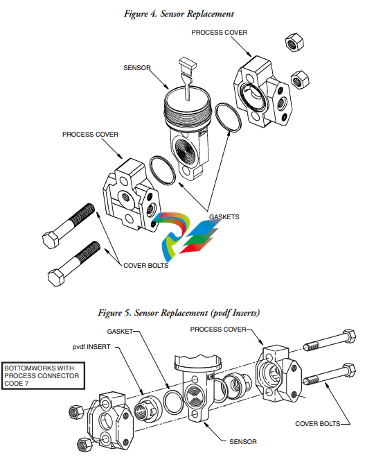
assembly by applying a hydrostatic pressure of 150% of the maximum static and
overrange pressure rating to both sides of the process cover/sensor assembly
simultaneously through the process connections. Hold pressure for one minute. There
should be no leakage of the test fluid through the gaskets.
Process Fluid Warning
! WARNING
If process containing parts are to be disassembled:
1. Make sure that process fluid is not under pressure or at high temperature.
2. Take proper precautions concerning leakage or spillage of any toxic or otherwise
dangerous fluid. Follow any Material Safety Data Sheet (MSDS)
recommendations.
Seal or Sensor Fill Fluid Warning
! WARNING
Even though the volume of fill fluid is small, be sure that the fill fluid can mix safely
with the process fluid.
Parts Replacement Warning
! WARNING
This product contains components that have critical safety characteristics. Do not
substitute components. Replace components only with identical factory supplied
components. Component substitution may impair the electrical safety of this
equipment and its suitability for use in hazardous locations.
EU Declaration of Conformity
We, Manufacturer:
Invensys Systems, Inc.
38 Neponset Ave.
Foxboro, Massachusetts 02035
U.S.A.
declare under our sole responsibility that the
I/A Series Pressure Transmitters IGP, IAP, IDP, IPI, IMV
are in conformity with the protection requirements of Council Directives:
♦ 2004/108/EC on the approximation of the laws of the Member States relating to
Electromagnetic Compatibility
♦ 94/9/EC on the approximation of the laws of the Member States concerning
equipment and protective systems intended for use in potentially explosive
atmospheres
♦ 2014/68/EU on the approximation of the laws of the Member States concerning
pressure equipment
The basis on which Conformity is being declared:
♦ EN 61326-1:2006, Electrical equipment for measurement, control and laboratory use
EMC requirements, Class A emission limits, and immunity requirements according to
Table 2 for Industrial locations.
♦ EN50014 1997 A1 1999 A2 1999 Electrical apparatus for potentially explosive
atmospheres 'General Requirements'.
♦ EN50018 2000 Electrical apparatus for potentially explosive atmospheres
'Flameproof enclosures 'd''.
♦ EN50020 1995 Electrical apparatus for potentially explosive atmospheres 'Intrinsic
safety 'I''.
♦ EN50021 1999 Electrical apparatus for potentially explosive atmospheres 'Type of
protection 'n''.
♦ EN50284 1999 Special requirements for construction, test and marking of electrical
apparatus of group II Category 1 G.
♦ EN 50281-1-1 1999 Electrical apparatus for use in the presence of combustible dust.
♦ EN 60079-15 2003 Electrical apparatus for explosive gas atmospheres - Part 15:
Electrical apparatus with type of protection "n"
For compliance with ATEX, products are in accordance with EC Type Examination Certificates
KEMA 00ATEX 1060X, KEMA 00ATEX 2019X and KEMA 00ATEX 1009X, issued by KEMA
Quality B.V., Ultrechtseweg 310, 6812 AR Arnhem, The Netherlands, Notified Body number
0344, and with EC Type Examination Certificates SIRA 04ATEX1349, SIRA 04ATEX2335X,
SIRA 06ATEX4056X, SIRA 06ATEX2055X, and SIRA 06ATEX4019X, issued by Sira
Certification Service, Rake Lane, Eccleston, Chester, CH4 9JN, England, Notified Body number
0518. The authorized markings for each certificate are shown below. The actual ATEX markings
on the product vary according to model code. Refer to Product Specification Sheet and marking
on product for details pertaining to individual model codes.
KEMA 00ATEX1060X II 3 G EEx nL IIC T4 … T6
II 1 GD EEx nL IIC T4 … T6 T 135°C
KEMA 00ATEX1009X II 1 G EEx ia IIC T4 … T6
II 1/2 G EEx ib IIC T4 … T6
II 1 GD EEx ia IIC T4 … T6 T 135°C
II 1/2 GD EEx ib IIC T4 … T6 T 135°C
KEMA 00ATEX2019X II 2 G EEx d IIC T6
II 2 GD EEx d IIC T6 T 85°C
SIRA 04ATEX1349 II 2 GD EEx d IIC T6 T 85°C
SIRA 04ATEX2335X II 1G EEx ia IIC T4
SIRA 06ATEX4056X II 3 GD EEx nL IIC T4
SIRA 06ATEX2055X II 1 GD EEx ia IIC T4
SIRA 06ATEX4019X II 3 G EEx nL IIC T4
For the Pressure Equipment Directive, conformity is based on a certificate issued by DNV GL,
Veritasveien 1, 1322 HOVIK, Norway, Notified Body number 0496, based on Maximum
Working Pressure (MWP). Conformity Assessment Module "H" is applied for Models IGP, IAP,
IMV and IDP where the MWP is greater than 200 bar. The applicable design standard is
IEC/EN 61010-1
. Installation
! CAUTION
To avoid damage to the transmitter sensor, do not use any impact devices, such as an
impact wrench or stamping device, on the transmitter.
NOTE
1. The transmitter should be mounted so that any moisture condensing or draining
into the field wiring compartment can exit through one of the two threaded
conduit connections.
2. Use a suitable thread sealant on all connections.
3. If the transmitter is not installed in the vertical position, readjust zero output to
-
 Hirschmann RS20-1600M2T1SDAEHH03.1.02 Rail Switch
 -
 Hirschmann BRS30-24TX Industrial Rail Switch
 -
 Hirschmann RSPM20-4T14T1EV9HHS999.9.99 Managed Ethernet Switch
 -
 Hirschmann BELDEN RS40-0009CCCCSDAPHH09.0.14 / RS400009CCCCSDAPHH09014
 -
Hirschmann RS40 Rail Switch RS40-0009CCCCSDAE
-
 Hirschmann BELDEN RS30-0802T1T1SDAP / RS300802T1T1SDAP Fully Managed Layer 2 Compact Rail Switch
 -
 Hirschmann BELDEN RS20-0800M2M2SDAUHH / RS200800M2M2SDAUHH
 -
 Hirschmann EAGLE30-04022O6TT999SCCY9HSE3F Industrial Firewall Router Switch
 -
 Hirschmann RS20-1600T1T1SDAEHH09.0.14 RS20 Rail Mount Ethernet Switch
 -
 Hirschmann EAGLE0200T1T1TDDY90000HHE05.3.03 Industrial Security Router
 -
Hirschmann - BELDEN MIPP-AD-1L9P
-
 HIRSCHMANN RSPM20-4Z64Z6TV9HHS9 942 106-999 RAIL SAFETY SWITCH
 -
 HIRSCHMANN FIBEROPTIC MODULE FIP P/N: OZDFIPG3T
 -
 HIRSCHMANN RS20-1600M2M2SDAUHH Ethernet rack-mounted switch
 -
 HIRSCHMANN BELDEN RS20-0400T1T1SDAEHH04.0.01 / RS200400T1T1SDAEHH04001
 -
HIRSCHMANN MM2-4FXM3 MICE Media Module
-
HIRSCHMANN RS20-0800M2M2SDAE Industrial Ethernet Rail Switch
-
 Hirschmann RS20-2400T1T1SDAP / RS20-2400T1T1SDAPHH05.0.02
 -
 GE MLJ1005B010H00C MLJ Digital Synchromism Check
 -
 ALSTOM MICROTECH DX21-M2 Digital Excitation Controller
 -
HIRSCHMANN BRS20-1200ZZZZ-STCY99HHSES
-
 HIRSCHMANN MM3-4FXM2 MICE Media Module
 -
Hirschmann RSB20-0800T1T1SAABHH 8Port ENet Rail Switch RSB20
-
 Hirschmann MACH102-8TP Ethernet Switch
 -
 SAACKE DDZ-M marine steam pressure atomizer
 -
 SAACKE SKV-A marine rotary cup atomizer
 -
 SAACKE Seavis HMI05e
 -
 Kollmorgen MMC-SD-2.0-230 Servo Drive 100-240VAC 2KW 10A Output 3PH 100-240VAC
 -
 Kollmorgen Servo drive CR10550
 -
 Kollmorgen AKD-P01207-NACN-0054 Servo Driver
 -
 Kollmorgen S406M-CA-036 Servostar
 -
.png) Kollmorgen AKD-B02407-NAAN-0000 Digital Servo Drive
Kollmorgen AKD-B02407-NAAN-0000 Digital Servo Drive -
 Kollmorgen SERVOSTAR S406AM-CA Digital Servo Drive
 -
 KOLLMORGEN SERVOSTAR 603-AS SERVO AMPLIFIER_SERVOSTAR603AS_S60301
 -
Kollmorgen S700 Servo Controller (S70602-NANANA-NA)
-
 Kollmorgen MPK411 controller
 -
 KOLLMORGEN MMC-SD-1.3-460-D Smart Drive
 -
 KOLLMORGEN AKM21C-CKB2AA-00 / AKM21CCKB2AA00 Servomotor
 -
 BECKHOFF AX5106-0000-0200 | Digital Compact Servo Drives 1-channel
 -
 BECKHOFF C3620-0000 INDUSTRIAL COMPUTER (MOTORSHELVES)
 -
 Beckhoff EK1960-0000 TwinSAFE Compact Controller
 -
 Beckhoff C6930-0050 Control Cabinet Industrial PC
 -
 Beckhoff CP7711-0001-0030 Industrial Computer Detection
 -
 Beckhoff CX1001-0111 Embedded PC CPU Module
 -
 Beckhoff C6017-0020 | Ultra-compact Industrial PC
 -
 Beckhoff EK1322 | 2-port EtherCAT P junction with feed-in
 -
 Beckhoff CP2219-0010 Panel
 -
 BECKHOFF C6015-0020 ULTRA COMPACT INDUSTRIAL PC
 -
 BECKHOFF CX2030-0120/Standard CPU Module Embedded PC Windows PLC controller
 -
 Beckhoff CP7721-1090-0020 Panel PC
 -
 Beckhoff PC CPU Module CX5130-0175
 -
 Beckhoff C6920-0050 Control Cabinet
 -
 Beckhoff EL6631 EtherCAT 2-Port Communication Interface, Profinet RT Controller
 -
 Beckhoff CP6202-0001-0060 touch screen panel PC
 -
 Beckhoff CP3916-1002-0000 Multi-Touch Control Panel
 -
 Beckhoff EP1809-0021 | EtherCAT Box, 16-channel digital input, 24 V DC, 3 ms, M8Preferred type
 -
 Beckhoff CX8190 PLC Embedded Industrial PC Ethernet Controller
 -
 Beckhoff CX2100-0914 Power Supply for External
 -
 Beckhoff Automation CP6906-0001-0000 HMI
 -
 Beckhoff EP7342-0002 Module
 -
 Beckhoff CX1020-0112 / CX1100-0910 / CX1020-N010 / CX1100-0003 Windows CPU
 -
 Beckhoff EP7211-0034 EtherCAT Box 1 Channel Motion Interface
 -
 Beckhoff C6240-0030 Control cabinet Industrial PC
 -
 beckhoff motherboard CB1052-0004 CB1052-0004
 -
 Beckhoff AX2006-AS Servo Drive / Variable Frequency Drive
 -
BECKHOFF CP6207-0001-0020 NSMP
-
 Beckhoff C6930-1142-0060 Industrial Computer
 -
 Beckhoff FC7501-0000 interface card
 -
 Beckhoff CX5140-0175 Embedded PC PLC CPU CX5140 Industrial Controller
 -
 Beckhoff CP7802-1100-0010: High-End IP65 Control Panel with DVI/USB Extended Interface
 -
BECKHOFF CP3716-1058-0010 CONTROL PANEL
-
 Beckhoff AX8108-0000 Single-Axis Module
 -
 Beckhoff CU8851-0000 | USB extension, USB Extended 2.0 receiver box
 -
Beckhoff C6017-0030 | Ultra-compact Industrial PC
-
 Beckhoff CX1001-0120/CX10010120.cx1000-n001.cx1000-n000 System Overview
 -
 Beckhoff CPU Module CX5140-0155/4GB CPU Module
 -
 Beckhoff CP6533-0001-005: Built-in Panel PC with High-Definition Multi-Touch Control
 -
 Beckhoff EL5042 | EtherCAT Terminal, 2-channel encoder interface, BiSS® C
 -
 Beckhoff C6920-1080-0040: Premium Control Cabinet Industrial PC
 -
 Beckhoff C6920-0060 | Control cabinet Industrial PC
 -
 Beckhoff Embedded-PC CX5010-1121
 -
 Beckhoff CB3050-0010 Mainboard Motherboard
 -
 Beckhoff PLC module CX1020-0000 Basic CPU module (service phase)
 -
 Beckhoff CP7812-1056-0010 15" Multitouch Display Control Panel
 -
 Beckhoff CX5120-0115 /2GB Controller Module
 -
 Beckhoff CP7201-1000-0000 Industrial Panel PC
 -
 Beckhoff Servo Motor AM8061-0JH1-0000
 -
 BECKHOFF CP6503-0001-0050 Built-in Panel PC
 -
Beckhoff CP3919-0010 Display G190ETN01.2 19" PCT V04. Multi-touch Control Panel
-
 Beckhoff CX5110-0112-9020/000368201 Embedded PC Intel Atom Processor
 -
 Beckhoff AX8206-0000 Dual-Axis Module
 -
Beckhoff Nail Operating Terminal CP7032-1031-0010
-
Beckhoff AM8042-0EH1-0000 Servomotor 4.10 Nm (M0), F4 (87 mm)
-
 Beckhoff EK9300 Beckhoff CPU Module
 -
Beckhoff CP3224-0020 Multitouch-Panel-PC
-
 Beckhoff CP2712-0000 12.1" 24VDC Touch Screen WMD0
 -
 BECKHOFF CX5240-0195 / 0000289234 Embedded PC 40 GB CFast Card
 -
 Beckhoff CP6932-1000-0000 Control Panel
 -
 BECKHOFF CX5120-0121 PLC Module
 -
 Beckhoff EL3218 | EtherCAT Terminal, 8-channel analog input
 -
Beckhoff C6640-0050 | Control cabinet Industrial PC
-
 Beckhoff Cx5130-0120/4GB Embedded-PC
 -
 BECKHOFF CX2030-0122 PLC PROCESSOR
 -
 BECKHOFF CX5020-0122 Controller Module
 -
 Beckhoff CP3915-0000 Multitouch Panel
 -
 BECKHOFF EL3014 | EtherCAT Terminal
 -
 BECKHOFF Industrial Computer c6920-1057-0030
 -
 Beckhoff CX5130-0141/4GB CX5130-0141 Embedded PC
 -
 Beckhoff C6240-1052-0040 4-086-06-3073 Industrial Computer
 -
 Beckhoff CX5140-0135 /4GB High-Performance Embedded Industrial PC
 -
 Beckhoff C6515-1001-0000 Industrial PC
 -
 Beckhoff AX5103-0000-0200 - Digital Compact Servo Drives
 -
 Beckhoff CX2030-0130-1003/4GB Basic CPU module
 -
 Beckhoff AX8620-0000 Power Supply Module
 -
 Beckhoff CX9020-0111 module with
 -
 Beckhoff EL7332 PLC Module
 -
 BECKHOFF CP7709-0001-0020 HMI
 -
 Beckhoff CX5120-0155/2GB Embedded PC
 -
 BECKHOFF CP7037-1037-0010 OPERATOR INTERFACE TOUCHSCREEN
 -
 Beckhoff EK9000 | ModbusTCP/UDP Bus Coupler
 -
 Beckhoff Touch Panel Screen CP6020 -0000-0000
 -
 Beckhoff CX2020-0121 Module FAST Shipping
 -
 Beckhoff CX2030-0125 Basic CPU Module
 -
 Beckhoff CP3918-0000 Multi-Touch 18.5" Control Panel
 -
 Automotion LC4A00010 DC BL Motor Control, ATS, Sub Assy, SCP, 115VAC,
 -
 500T-115VAC - VAS ENGINEERING - DORIC 500 SERIES DIGITAL TEMP INDICATOR
 -
 Honeywell X-DCS2000/EN Digital Integrated System Manager 50/60Hz 100-240V #4
 -
 Kollmorgen S60600 Servostar600 606-Fan 4 kVA, 6 A, 3 X 230 - 480 V


