
schneiderUniversal Instruction Manual I/A Series® Pressure Transmitters Models IAP10, IAP20, IGP10, IGP20, IGP25 and IGP50, IDP10, IDP25, IDP50 Configuration, Calibration, Installation, and Operation
This Universal Instruction Manual is designed to provide the user with a single, concise, easy-touse manual that covers the key points needed for configuration, calibration, installation, and
operation of I/A Series Pressure Transmitters.
It covers all models of single variable pressure transmitters in the I/A Series family, including
absolute, gauge, and differential pressure transmitters, with FoxCom, HART, FOUNDATION
Fieldbus, or analog output electronics.
This universal manual, along with a DVD containing detailed information, is provided free of
charge with every I/A Series Pressure Transmitter, unless the purchaser requests that these two
items be omitted.
For additional detailed information about each model, including dimensional prints, parts lists,
and more detailed instructions, please refer to the standard DVD supplied or the optional paper
instruction book that is available for each model in the line.
♦ Standard Documentation Shipped with every I/A Series Pressure Transmitter
♦ A brief “Getting Started” Pocket-Sized Bulletin
♦ This Universal Instruction Manual
♦ A DVD that contains the complete documentation set for I/A Series Pressure
Transmitters
♦ When Optional Feature K1 is specified in the Model Code when the transmitter is
ordered:
A brief “Getting Started” Pocket-Sized Bulletin only is supplied
Optional Feature K1 is offered for those users who want to omit the documentation
shipped with every transmitter. This may be specified when multiple identical
transmitters are ordered and the user does not want multiple sets of documentation.
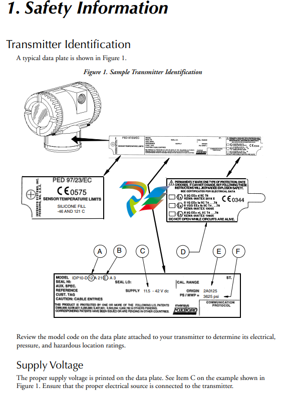
Electrical Certification Rating
The electrical safety design code is printed on the data plate as part of the model code. See Item B
on the example shown in Figure 1. See the "Product Safety Specifications" section of the
instruction pertaining to your instrument on the enclosed DVD to identify this code. The type of
protection is also marked on the data plate. See Item D on the example shown in Figure 1.
PED Certification
The PED (Harmonized Pressure Equipment Directive for the European Community)
certification is offered only with transmitters ordered with ATEX Electrical Safety Design Code
selections. Transmitters with PED certification have a CE marking on the data plate that also
carries the PED number 0496.
Pressure Rating
The maximum working pressure (PS or MWP) for the transmitter is printed on the data plate.
See Item F on the example shown in Figure 1.
The data plate of flanged level transmitters and transmitters with flanged pressure seals are
stamped with the MWP if the transmitter pressure range is the limiting factor. It is stamped
“Flange Rate” if the flange rating is the limiting factor. The MWP of the flanged seal is stamped
on the seal data plate. See Figure 2.
Figure 2. Sample Seal Data Plate
When using transmitters with threaded, in-line saddle weld, or sanitary pressure seals, compare
the MWP of the transmitter on the transmitter data plate and the MWP of the seals on the seals
data plates and use the lesser value as the system MWP.
The MWP on the seal data plates may not be given at your process temperature. Use the
following information and industry standards as required to determine the actual pressure limits
for your application.
MODEL CODE: PSFPS-A2S0E313B MWP: 275 psig at 100°F
NOTICE: BREAKING CONNECTIONS VOIDS WARRANTY
BE SURE FILL FLUID CAN MIX SAFELY WITH PROCESS HIGH SIDE SEAL
HIGH SIDE FLUID, DC200, 10 cSt SILICONE TEMP RANGE -40 TO +450°F
PROCESS WETTED MATERIAL 316 SS
essure Seal PSFLT
Table 1. Pressure Seal PSFLT Pressure Limits
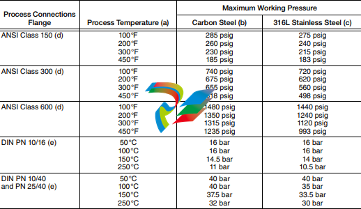
a. Flange temperature/pressure ratings only; seal temperature ratings may be lower; refer to Table 8
b. ASME/ANSI Material Group 1.1; linear interpolation acceptable
c. ASME/ANSI Material Group 2.2; linear interpolation acceptable
d. ANSI flanges per ASME/ANSI B16.5-1988.
e. DIN flanges per BS4504.
Pressure Seals PSFPS and PSFES
Table 2. Pressure Seal PSFPS and PSFES Pressure Limits
Pressure Seals PSSCR and PSSCT
The maximum working pressure of the seal process connection varies with the clamping device
used. Refer to Tri-Clover Tri-Clamp standards to determine the pressure limits of the clamping
system that you are using.
PSSSR and PSSST (Sanitary Tank Spud) Seals
The maximum working pressure of mini tank spud seal is 1.55 MPa at 120°C (225 psi at 250°F).
That of the standard tank spud seal is 1.38 MPa at 120°C (200 psi at 250°F).
Origin Code
The origin code identifies the area of manufacture and the year and week of manufacture. See
Item E on the example shown in Figure 1. In the example, 2A means the product was
manufactured in the Measurement and Instrument Division, 01 identifies the year of
manufacture as 2001, and 25, the week of manufacture in that year.
Operating Temperature Limits
The operating temperature limits of the electronics are -40°C and +85°C (-40°F and +185°F).
The limits are -40°C and +75°C (-40°F and +167°F) for IAP10, IGP10, IGP25, and IGP50
-
 Hirschmann RS20-1600M2T1SDAEHH03.1.02 Rail Switch
 -
 Hirschmann BRS30-24TX Industrial Rail Switch
 -
 Hirschmann RSPM20-4T14T1EV9HHS999.9.99 Managed Ethernet Switch
 -
 Hirschmann BELDEN RS40-0009CCCCSDAPHH09.0.14 / RS400009CCCCSDAPHH09014
 -
Hirschmann RS40 Rail Switch RS40-0009CCCCSDAE
-
 Hirschmann BELDEN RS30-0802T1T1SDAP / RS300802T1T1SDAP Fully Managed Layer 2 Compact Rail Switch
 -
 Hirschmann BELDEN RS20-0800M2M2SDAUHH / RS200800M2M2SDAUHH
 -
 Hirschmann EAGLE30-04022O6TT999SCCY9HSE3F Industrial Firewall Router Switch
 -
 Hirschmann RS20-1600T1T1SDAEHH09.0.14 RS20 Rail Mount Ethernet Switch
 -
 Hirschmann EAGLE0200T1T1TDDY90000HHE05.3.03 Industrial Security Router
 -
Hirschmann - BELDEN MIPP-AD-1L9P
-
 HIRSCHMANN RSPM20-4Z64Z6TV9HHS9 942 106-999 RAIL SAFETY SWITCH
 -
 HIRSCHMANN FIBEROPTIC MODULE FIP P/N: OZDFIPG3T
 -
 HIRSCHMANN RS20-1600M2M2SDAUHH Ethernet rack-mounted switch
 -
 HIRSCHMANN BELDEN RS20-0400T1T1SDAEHH04.0.01 / RS200400T1T1SDAEHH04001
 -
HIRSCHMANN MM2-4FXM3 MICE Media Module
-
HIRSCHMANN RS20-0800M2M2SDAE Industrial Ethernet Rail Switch
-
 Hirschmann RS20-2400T1T1SDAP / RS20-2400T1T1SDAPHH05.0.02
 -
 GE MLJ1005B010H00C MLJ Digital Synchromism Check
 -
 ALSTOM MICROTECH DX21-M2 Digital Excitation Controller
 -
HIRSCHMANN BRS20-1200ZZZZ-STCY99HHSES
-
 HIRSCHMANN MM3-4FXM2 MICE Media Module
 -
Hirschmann RSB20-0800T1T1SAABHH 8Port ENet Rail Switch RSB20
-
 Hirschmann MACH102-8TP Ethernet Switch
 -
 SAACKE DDZ-M marine steam pressure atomizer
 -
 SAACKE SKV-A marine rotary cup atomizer
 -
 SAACKE Seavis HMI05e
 -
 Kollmorgen MMC-SD-2.0-230 Servo Drive 100-240VAC 2KW 10A Output 3PH 100-240VAC
 -
 Kollmorgen Servo drive CR10550
 -
 Kollmorgen AKD-P01207-NACN-0054 Servo Driver
 -
 Kollmorgen S406M-CA-036 Servostar
 -
.png) Kollmorgen AKD-B02407-NAAN-0000 Digital Servo Drive
Kollmorgen AKD-B02407-NAAN-0000 Digital Servo Drive -
 Kollmorgen SERVOSTAR S406AM-CA Digital Servo Drive
 -
 KOLLMORGEN SERVOSTAR 603-AS SERVO AMPLIFIER_SERVOSTAR603AS_S60301
 -
Kollmorgen S700 Servo Controller (S70602-NANANA-NA)
-
 Kollmorgen MPK411 controller
 -
 KOLLMORGEN MMC-SD-1.3-460-D Smart Drive
 -
 KOLLMORGEN AKM21C-CKB2AA-00 / AKM21CCKB2AA00 Servomotor
 -
 BECKHOFF AX5106-0000-0200 | Digital Compact Servo Drives 1-channel
 -
 BECKHOFF C3620-0000 INDUSTRIAL COMPUTER (MOTORSHELVES)
 -
 Beckhoff EK1960-0000 TwinSAFE Compact Controller
 -
 Beckhoff C6930-0050 Control Cabinet Industrial PC
 -
 Beckhoff CP7711-0001-0030 Industrial Computer Detection
 -
 Beckhoff CX1001-0111 Embedded PC CPU Module
 -
 Beckhoff C6017-0020 | Ultra-compact Industrial PC
 -
 Beckhoff EK1322 | 2-port EtherCAT P junction with feed-in
 -
 Beckhoff CP2219-0010 Panel
 -
 BECKHOFF C6015-0020 ULTRA COMPACT INDUSTRIAL PC
 -
 BECKHOFF CX2030-0120/Standard CPU Module Embedded PC Windows PLC controller
 -
 Beckhoff CP7721-1090-0020 Panel PC
 -
 Beckhoff PC CPU Module CX5130-0175
 -
 Beckhoff C6920-0050 Control Cabinet
 -
 Beckhoff EL6631 EtherCAT 2-Port Communication Interface, Profinet RT Controller
 -
 Beckhoff CP6202-0001-0060 touch screen panel PC
 -
 Beckhoff CP3916-1002-0000 Multi-Touch Control Panel
 -
 Beckhoff EP1809-0021 | EtherCAT Box, 16-channel digital input, 24 V DC, 3 ms, M8Preferred type
 -
 Beckhoff CX8190 PLC Embedded Industrial PC Ethernet Controller
 -
 Beckhoff CX2100-0914 Power Supply for External
 -
 Beckhoff Automation CP6906-0001-0000 HMI
 -
 Beckhoff EP7342-0002 Module
 -
 Beckhoff CX1020-0112 / CX1100-0910 / CX1020-N010 / CX1100-0003 Windows CPU
 -
 Beckhoff EP7211-0034 EtherCAT Box 1 Channel Motion Interface
 -
 Beckhoff C6240-0030 Control cabinet Industrial PC
 -
 beckhoff motherboard CB1052-0004 CB1052-0004
 -
 Beckhoff AX2006-AS Servo Drive / Variable Frequency Drive
 -
BECKHOFF CP6207-0001-0020 NSMP
-
 Beckhoff C6930-1142-0060 Industrial Computer
 -
 Beckhoff FC7501-0000 interface card
 -
 Beckhoff CX5140-0175 Embedded PC PLC CPU CX5140 Industrial Controller
 -
 Beckhoff CP7802-1100-0010: High-End IP65 Control Panel with DVI/USB Extended Interface
 -
BECKHOFF CP3716-1058-0010 CONTROL PANEL
-
 Beckhoff AX8108-0000 Single-Axis Module
 -
 Beckhoff CU8851-0000 | USB extension, USB Extended 2.0 receiver box
 -
Beckhoff C6017-0030 | Ultra-compact Industrial PC
-
 Beckhoff CX1001-0120/CX10010120.cx1000-n001.cx1000-n000 System Overview
 -
 Beckhoff CPU Module CX5140-0155/4GB CPU Module
 -
 Beckhoff CP6533-0001-005: Built-in Panel PC with High-Definition Multi-Touch Control
 -
 Beckhoff EL5042 | EtherCAT Terminal, 2-channel encoder interface, BiSS® C
 -
 Beckhoff C6920-1080-0040: Premium Control Cabinet Industrial PC
 -
 Beckhoff C6920-0060 | Control cabinet Industrial PC
 -
 Beckhoff Embedded-PC CX5010-1121
 -
 Beckhoff CB3050-0010 Mainboard Motherboard
 -
 Beckhoff PLC module CX1020-0000 Basic CPU module (service phase)
 -
 Beckhoff CP7812-1056-0010 15" Multitouch Display Control Panel
 -
 Beckhoff CX5120-0115 /2GB Controller Module
 -
 Beckhoff CP7201-1000-0000 Industrial Panel PC
 -
 Beckhoff Servo Motor AM8061-0JH1-0000
 -
 BECKHOFF CP6503-0001-0050 Built-in Panel PC
 -
Beckhoff CP3919-0010 Display G190ETN01.2 19" PCT V04. Multi-touch Control Panel
-
 Beckhoff CX5110-0112-9020/000368201 Embedded PC Intel Atom Processor
 -
 Beckhoff AX8206-0000 Dual-Axis Module
 -
Beckhoff Nail Operating Terminal CP7032-1031-0010
-
Beckhoff AM8042-0EH1-0000 Servomotor 4.10 Nm (M0), F4 (87 mm)
-
 Beckhoff EK9300 Beckhoff CPU Module
 -
Beckhoff CP3224-0020 Multitouch-Panel-PC
-
 Beckhoff CP2712-0000 12.1" 24VDC Touch Screen WMD0
 -
 BECKHOFF CX5240-0195 / 0000289234 Embedded PC 40 GB CFast Card
 -
 Beckhoff CP6932-1000-0000 Control Panel
 -
 BECKHOFF CX5120-0121 PLC Module
 -
 Beckhoff EL3218 | EtherCAT Terminal, 8-channel analog input
 -
Beckhoff C6640-0050 | Control cabinet Industrial PC
-
 Beckhoff Cx5130-0120/4GB Embedded-PC
 -
 BECKHOFF CX2030-0122 PLC PROCESSOR
 -
 BECKHOFF CX5020-0122 Controller Module
 -
 Beckhoff CP3915-0000 Multitouch Panel
 -
 BECKHOFF EL3014 | EtherCAT Terminal
 -
 BECKHOFF Industrial Computer c6920-1057-0030
 -
 Beckhoff CX5130-0141/4GB CX5130-0141 Embedded PC
 -
 Beckhoff C6240-1052-0040 4-086-06-3073 Industrial Computer
 -
 Beckhoff CX5140-0135 /4GB High-Performance Embedded Industrial PC
 -
 Beckhoff C6515-1001-0000 Industrial PC
 -
 Beckhoff AX5103-0000-0200 - Digital Compact Servo Drives
 -
 Beckhoff CX2030-0130-1003/4GB Basic CPU module
 -
 Beckhoff AX8620-0000 Power Supply Module
 -
 Beckhoff CX9020-0111 module with
 -
 Beckhoff EL7332 PLC Module
 -
 BECKHOFF CP7709-0001-0020 HMI
 -
 Beckhoff CX5120-0155/2GB Embedded PC
 -
 BECKHOFF CP7037-1037-0010 OPERATOR INTERFACE TOUCHSCREEN
 -
 Beckhoff EK9000 | ModbusTCP/UDP Bus Coupler
 -
 Beckhoff Touch Panel Screen CP6020 -0000-0000
 -
 Beckhoff CX2020-0121 Module FAST Shipping
 -
 Beckhoff CX2030-0125 Basic CPU Module
 -
 Beckhoff CP3918-0000 Multi-Touch 18.5" Control Panel
 -
 Automotion LC4A00010 DC BL Motor Control, ATS, Sub Assy, SCP, 115VAC,
 -
 500T-115VAC - VAS ENGINEERING - DORIC 500 SERIES DIGITAL TEMP INDICATOR
 -
 Honeywell X-DCS2000/EN Digital Integrated System Manager 50/60Hz 100-240V #4
 -
 Kollmorgen S60600 Servostar600 606-Fan 4 kVA, 6 A, 3 X 230 - 480 V


