
EMERSONFloBoss™ S600+ Flow Computer Instruction Manual
Device Safety Considerations
Reading these Instructions
Before operating the device, read these instructions carefully and understand their safety implications. In some
situations, improperly using this device may result in damage or injury. Keep this manual in a convenient location
for future reference. Note that these instructions may not cover all details or variations in equipment or cover every
possible situation regarding installation, operation, or maintenance. Should problems arise that are not covered
sufficiently in the text, immediately contact Customer Support for further information.
Protecting Operating Processes
A failure of this device – for whatever reason -- may leave an operating process without appropriate protection and
could result in possible damage to property or injury to persons. To protect against this, you should review the
need for additional backup equipment or provide alternate means of protection (such as alarm devices, output
limiting, fail-safe valves, relief valves, emergency shutoffs, emergency switches, etc.). Contact Remote Automation
Solutions for additional information.
Returning Equipment
If you need to return any equipment to Remote Automation Solutions, it is your responsibility to ensure that the
equipment has been cleaned to safe levels, as defined and/or determined by applicable federal, state and/or local
law regulations or codes. You also agree to indemnify Remote Automation Solutions and hold Remote Automation
Solutions harmless from any liability or damage which Remote Automation Solutions may incur or suffer due to
your failure to ensure device cleanliness.
Grounding Equipment
Ground metal enclosures and exposed metal parts of electrical instruments in accordance with OSHA rules and
regulations as specified in Design Safety Standards for Electrical Systems, 29 CFR, Part 1910, Subpart S, dated:
April 16, 1981 (OSHA rulings are in agreement with the National Electrical Code). You must also ground
mechanical or pneumatic instruments that include electrically operated devices such as lights, switches, relays,
alarms, or chart drives.
Important: Complying with the codes and regulations of authorities having jurisdiction is essential to ensuring
personnel safety. The guidelines and recommendations in this manual are intended to meet or exceed applicable
codes and regulations. If differences occur between this manual and the codes and regulations of authorities
having jurisdiction, those codes and regulations must take precedence.
Protecting from Electrostatic Discharge (ESD)
This device contains sensitive electronic components which be damaged by exposure to an ESD voltage.
Depending on the magnitude and duration of the ESD, it can result in erratic operation or complete failure of the
equipment. Ensure that you correctly care for and handle ESD-sensitive components.
System Training
A well-trained workforce is critical to the success of your operation. Knowing how to correctly install, configure,
program, calibrate, and trouble-shoot your Emerson equipment provides your engineers and technicians with the
skills and confidence to optimize your investment. Energy and Transportation Solutions offers a variety of ways for
your personnel to acquire essential system expertise. Our full-time professional instructors can conduct classroom
training at several of our corporate offices, at your site, or even at your regional Emerson office. You can also
receive the same quality training via our live, interactive Emerson Virtual Classroom and save on travel costs. For
our complete schedule and further information, contact the Energy and Transportation Solutions Training
Department at 800-338-8158 or email us at education@emerson.com.
Ethernet Connectivity
This automation device is intended to be used in an Ethernet network which does not have public access. The
inclusion of this device in a publicly accessible Ethernet-based network is not recommended
FloBoss S600+ Flow Computer
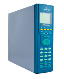
Figure 1-1. The FloBoss S600+ Flow Computer
The FloBoss S600+ Flow Computer is a panel-mounted (for indooruse) flow computer designed specifically to measure hydrocarbon
liquid and gas where versatility and accuracy matter. The standard
features of the S600+ make it ideal for fiscal measurement, custody
transfer, batch loading, and meter proving applications. The S600+
allows you to configure multi-stream, multi-station applications,
enabling you to simultaneously meter liquids and gasses.
The S600+ is designed for use either as a stand-alone flow computer or
as a system component. The intelligent I/O modules fit both gas and
liquid applications and typically support two dual-pulsed streams and a
header. Adding I/O modules (up to a maximum of three) allows you to
configure up to six dual-pulsed streams or up to 10 single-pulsed
streams and two headers. The S600+ supports orifice, ultrasonic,
turbine, positive displacement, Coriolis, Annubar, and V-Cone® flow
meter types and master meter, small volume compact, and pipe (both
bi-directional and uni-directional) proving methods.
The S600+ offers a variety of communication interfaces:
Two LAN ports (on the enhanced CPU module) for Ethernet
10Base-T or 100Base-T full-duplex connectivity (using either
Modbus TCP or Modbus over Ethernet protocols).
Note: The Ethernet module (P190), which provided an additional
Ethernet port for previous versions of the S600, is not
compatible with the S600+.
HART® communication using up to two 12-channel HART
modules, each of which supports point-to-point and multi-drop
architectures for up to 50 transmitters.
Note: The FloBoss S600+ is fully compatible with HART 5
devices, and HART 7 devices are backwards compatible
with HART 5 devices.
An embedded webserver allows remote access to the flow
computer. Security is provided using user name and password
protection with a detailed event log for audit purposes (supports
Microsoft® Edge™ or Windows® Internet Explorer® version 5 or
greater [version 9 or greater must use compatibility mode]).
Two configurable RS-232 serial ports.
Three RS-422/RS-485 serial ports (supporting up to 57,600 bps
baud) and up to four RS-485 2-wire serial ports (supporting up to
57,600 baud rate) for connection to intelligent meters, Modbus
SCADA data networks, DCS supervisory systems, and so on.
One dedicated configuration port (located on the bottom of front
display panel) for connection to the Config 600 configuration
software.
Additional communications interfaces include:
• Serial Q.Sonic®
• Serial printer
• Serial or Modbus TCP Daniel chromatograph via Modbus
• Serial peer-to-peer
• Modbus EFM protocol, Modbus RTU, Modbus ASCII, Modbus
over Ethernet, and Modbus TCP
Miscellaneous interfaces which can operate via serial or Modbus
TCP:
Daniel liquid ultrasonic
Daniel gas ultrasonic
Sick ultrasonic
Daniel chromatograph
Note: All ports can connect to DCS systems, ultrasonic meters,
Coriolis meters, and so on.
The S600+ uses distributed processing to achieve maximum
performance. The CPU module incorporates a hardware floating point
processor. Each additional module also has local processing to convert
inputs and output from engineering units to field values and vice-versa,
as well as running background tests and PID loops.
The firmware uses 64-bit (double) precision floating point numbers for
the highest accuracy when performing all metering calculations.
Cumulative totals are stored in three separate memory locations (Trireg format) for maximum integrity. The user language LogiCalc™ also
allows you to perform logical control and double-precision
mathematical functions on the database objects.
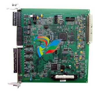
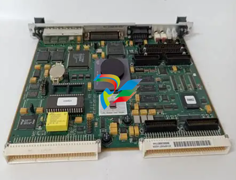
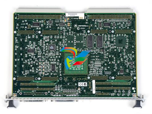
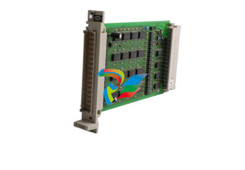
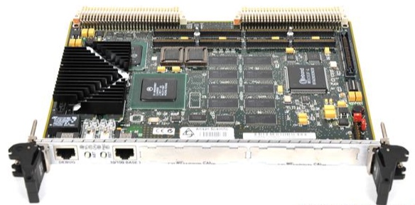
Figure 1-2. CPU Module
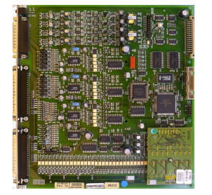
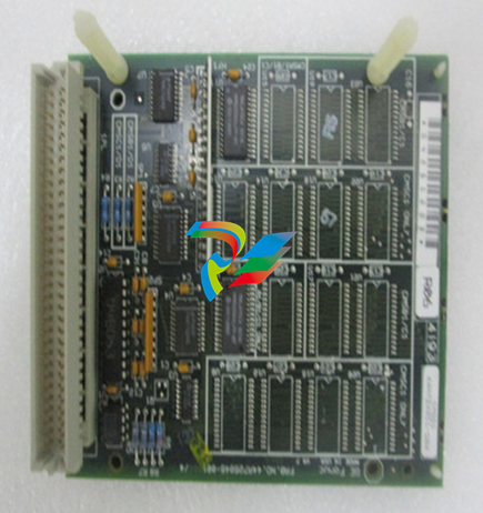
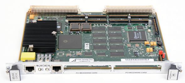
Figure 1-3. Intelligent I/O Module
Front Display
Panel
The S600+’s front panel interface enables you to manage an existing
configuration or create a configuration using the PC-based Config
600 configuration software.
A communications port on the bottom of the panel provides a way to
directly connect to a PC. The front panel interface consists of a backlit
LCD display, a 29-button keypad, and an alarm status LED (see Figure
1-4).
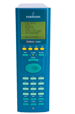
Figure 1-4. Front Display Panel
Config600 Configuration Software
Using Config 600, you can both send (upload) new or modified
configurations to the S600+ and receive (download) existing
configurations from the S600+. You can also define the following
functions:
Stream and station totalisation.
Batch totalisation and correction.
Three-term PID control.
Flow balancing.
Flow scheduling.
Automatic proving sequence.
K-factor or meter factor linearisation.
Valve monitor/control.
Sampler control.
Station densitometer.
Station gas chromatograph.
Forward, reverse, and premium error totals.
Comprehensive maintenance mode.
Reporting.
Modbus.
Modify display matrix.
Config600 is a suite of software editors that enables you to monitor,
configure, and calibrate the S600+. The software comes in three
versions – Config600 Lite, Config600 Lite Plus, and Config600 Pro –
with Config600 Pro being the most powerful version.
Note: The S600+ does not operate until you send a configuration to it
from the host PC.
IPL600 Remote Automation Solutions provides a separate utility program
called “Interactive Program Loader 600” (or “IPL600”).
Using IPL600 and an IP or a dedicated serial port connection between
a host PC and an S600+, you can transfer and receive configuration
files (reports, Modbus configurations, customised displays, and
LogiCalc programs). While included as the Config Transfer utility in
Config600, IPL600 has a standalone use for situations when you do not
need the full functionality of Config600. Details on using Config
Transfer/IPL600 are provided in the Config600 Software User Manual
(Part D301220X412).
1.3.1 Config600 Lite
Use the Config 600 Lite software editor suite to modify pre-developed
configurations, transfer existing configurations, edit items on the front
panel display, and customise reports.
Note: You typically use Config600 Lite to custom-configure a new
S600+ during installation.
With Config600 Lite you can:
Edit process configuration data, including orifice size, analog input
scaling, alarm limits, and keypad values.
Build and customise Modbus slave maps, Modbus master polling
sequences, front panel displays, and period report formats.
Customise the alarm system, including alarm groups, suppression,
and inhibits.
Configure system security by setting user names and passwords,
and assigning access levels for each data object on the displays.
Specify the engineering units and totalisation rollover value.
Reflash the CPU module firmware with software upgrades and
transfer configurations via the Config Transfer utility (IPL600).
1.3.2 Config600 Lite Plus
The Config600 Lite Plus software editor suite provides all the
functionality of the Config600 Lite suite, but adds the ability to create
a configuration file.
With Config600 Lite Plus you can:
Create a new application from base templates for gas, liquid, and
prover applications.
Edit process configuration data, including orifice size, analog input
scaling, alarm limits, and keypad values.
Build and customise Modbus slave maps, Modbus master polling
sequences, front panel displays, and period report formats.
Customise the alarm system, including alarm groups, suppression,
and inhibits.
Configure system security by setting user names and passwords,
and assigning access levels for each data object on the displays.
Specify the engineering units and totalisation rollover value.
Reflash the CPU module firmware with software upgrades and
transfer configurations via the Config Transfer utility (IPL600).
1.3.3 Config600 Pro
Use the Config600 Pro software editor suite to create new
configurations, modify existing configurations, transfer existing
configurations, edit items on the front panel display, and edit custom
reports.
With Config600 Pro you can:
Create a new application from base templates for gas, liquid, and
prover applications.
Edit process configuration data, including orifice size, analog input
scaling, alarm limits, and keypad values.
Build and customise Modbus slave maps, Modbus master polling
sequences, front panel displays, and period report formats.
Specify the engineering units and totalisation rollover value.
Customise the alarm system, including alarm groups, suppression,
text, and inhibits.
Configure system security by setting user names and passwords,
and assigning access levels for each data object.
Add and remove objects from the database.
Program special features using LogiCalc.
Reflash the CPU module firmware with software upgrades and
transfer configurations via the Config Transfer utility (IPL600).
Note: To obtain a Config600 Pro license you must first attend and
successfully complete a training course.
1.4 Additional Technical Information
Refer to the following technical documents (available at
www.Emerson.com/EnergyandTransportation) for additional and
most-current information.
Table 1-1. Related Technical Information
Name Form Number Part Number
FloBoss™ S600+ Flow Computer S600+ D301151X412
Config600™ Configuration Software Config600 D301164X012
Config600™ Configuration Software User Manual A6169 D301220X412
1.4.1 Open Source Software
The FloBoss S600+ contains open source software covered by the
GPL, GPL2, GPL3, LGPL, OpenSSL, SSLeay, zlib, libzip2, and
Apache open source software licenses. The specific software being
used is U-Boot, the Linux kernel, glibc, Apache web server, mod_sll,
mod_alias, mod_rewrite, OpenSSL, BusyBox, ntpclient, tar32, and
JFFS2. These licenses are contained on the S600+ Open Source
Software CD (part number S600SRCOPEN). Source code is available
upon request. You may obtain a copy of this source code by contacting
your local Remote Automation Solutions sales office. This product
includes software developed by the OpenSSL Project for use in the
OpenSSL Toolkit (http://www.openssl.org). This product includes
cryptographic software written by Eric Young (eay@cryptsoft.com).
Caution Failure to exercise proper electrostatic discharge precautions (such
as wearing a grounded wrist strap) when accessing the back of the
unit or when handling CPU or I/O modules may reset the processor
or damage electronic components, resulting in interrupted
operations.
2.1 Preparing for Installation
The S600+ installation must conform to all applicable local codes and
regulations. All installation procedures should be in accordance with
normal practices of good workmanship. Although the S600+ shipped
to you may not include all of the hardware options described in this
manual, the procedure for the basic installation of the unit remains the
same.
Note: We strongly recommend you familiarize yourself with the
procedures described in this chapter before you begin to install
the S600+.
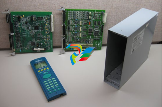
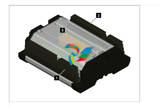
The S600+ uses a modular design that provides maximum flexibility
and ease of installation. The basic panel-mounted version consists of
three major components:
Fabricated metal case, complete with pre-installed PSU/backplane
and four card slots for the modules (a dedicated CPU slot and three
I/O slots).
Removable front panel comprising the LCD display and keypad
assembly.
Plug-in modules. A CPU module and one I/O module are supplied
for a basic configuration; two blank plates are supplied to cover the
unused slots.
Figure 2-1 shows the S600+ system components
Note: User-supplied tools to assist in the installation process may
include a Phillips screwdriver, a regular screwdriver, a small
adjustable spanner wrench, and a 2.5mm Allen key.
2.2 Environmental Considerations
The S600+ panel mounted flow computer is designed for use within
the control room. Place it in a position that provides ease of use,
comfort, and safety for operators and maintenance personnel. The
optimum height for viewing and using the display and keypad is at
operator eye level.
Caution If you install one or more units in a confined space with other heatproducing equipment, give special attention to the combined heating
effect. This combined heat could increase the environmental
temperature beyond its acceptable threshold, thereby impacting
performance.
2.3 Required Tools for Installation
Before you attempt to install the S600+, ensure that you have the
following tools:
Small flat-blade screwdriver suitable for the slot-headed captive
screws on the rear of the case that secure each plug-in board into
the case.
5.5 mm (5 BA) hex or small adjustable wrench for the front panel
bosses
2.5 mm Allen key suitable for the hex cap screw on the front face
of the front panel that secures the front panel molding to the case.
2.4 Installing the S600+
Refer to the following procedures for installing the various S600+
components, including the front panel, panel-mounted unit, and
modules.
2.4.1 Unpacking the S600+
Unpack the S600+ carefully and inspect parts for visual damage.
Note: Do not discard packaging material until after you have
identified all pieces of the shipment and you are confident that
all parts are working correctly.
2.4.2 Removing the Front Panel
To begin the mounting process, remove the front panel from the
S600+:
1. Ensure power has been removed from the S600+.
2. Using a 2.5 mm Allen key, remove the hex cap screw from the
bottom centre of the front panel (refer to Figure 2-2).
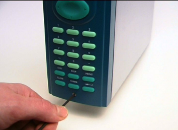
Note: A security cap may cover the hex cap screw.
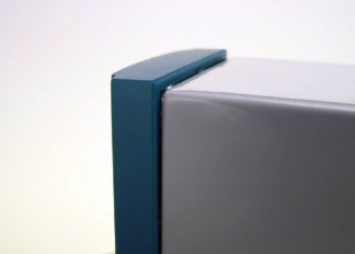
3. Carefully slide the front panel up 4 mm (0.15 in) to allow it to clear
the retaining groove at the top of the case, and then allow the panel
to come forward to clear the panel case completely (refer to Figure
2-3).
Figure 2-3. Lifted Front Panel
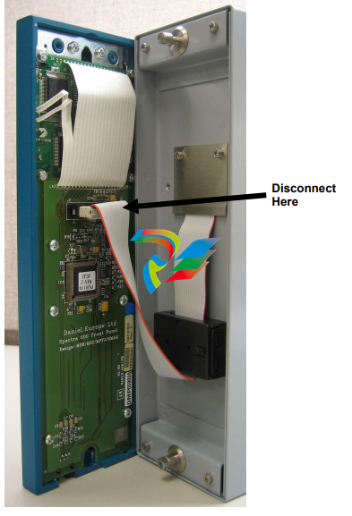
Disconnect the ribbon cable from the back of the front panel at the
blue connector (refer to Figure 2-4). Observe the orientation of the
connector with its mating keyway. You must correctly re-insert the
ribbon cable at the end of the installation process.
Caution Do not remove the ribbon cable from the S600+ housing. This might
damage the S600+. Also, the ribbon cable may also have an EMC
clamp. Be sure to leave it intact without damaging the ribbon cable.
5. Remove the top and bottom bosses from the unit housing, using a
5.5 mm (5 BA) hex wrench.
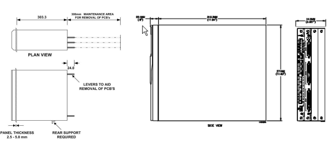
Table 2-1. Mounting Dimensions
Part Dimensions
Display Keypad Molding 85 mm (3.35") width x 269 mm (10.59") height x 28 mm (1.10") deep
Case 84.5 mm (3.327") width x 270 mm (10.63") height x 303.8 mm (11.94")
deep
Panel Cutout 66 mm (2.6") width x 150 mm (5.9") height
Pitch Between Cases 110 mm (4.33") giving 25 mm (0.98") air gap
Max Panel Thickness 10 mm (0.39")
Access Allow 300 mm (11.81") clearance directly behind case for maintenance
2.4.3 Installing the Panel-Mounted Unit
After removing the front panel, install the panel-mounted unit:
1. Keeping environmental considerations in mind, construct the
framework of the cubicle to support the operating panel.
Note: A standard 483 mm (19 in) rack that is 311 mm (12.25 in)
high can accommodate up to four S600+s provided you
support the rear of the case.
2. Refer to Figure 2-6 and Table 2-1 for position details for two 7 mm
(0.276 in) holes and a cutout. The panel cutout should be
rectangular for each S600+. Allow a tolerance of ± 3 mm (0.12 in)
on each axis.
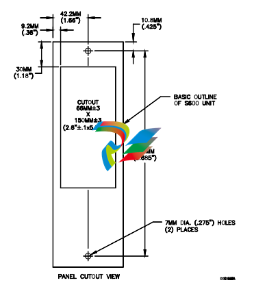
Note: The S600+ fits into existing S500 and 869 flow computer
panel cutouts.
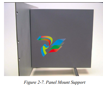
3. Ensure a panel thickness of at least 3 mm (0.12 in) to prevent
distortion. If you use a thinner panel, support the rear of the case
(refer to Figure 2-7).
Caution Always use a rear support or anchor to prevent twisting and other
distortion effects during installation and maintenance.
4. Place the front of the case against the rear of the prepared cutout.
5. Re-install the top and bottom bosses and tighten with a 5.5 mm (5
BA) hex wrench.
6. Once you have fitted the rear support, use a self-tapping screw to
secure the case to the rear support. The maximum depth of the
screw inside the case should be 3 mm (0.12 in).
2.4.4 Reinstalling the Front Panel
Re-installing the front panel is the final stage of the installation
process:
1. Connect the ribbon cable to the front panel.
Caution Note how the connector fits into the keyway. You must insert the
ribbon cable correctly. Do not force the connector into the keyway.
2. Place the top of the front panel over the retaining groove on the top
boss and slide the front panel downwards.
3. Secure the front panel by placing the hex cap screw into its recess
in the bottom centre of the front panel.
4. Using a 2.5 mm Allen key, tighten the screw finger-tight. Turn an
additional 180 degrees clockwise to complete the installation.
Note: Replace the security cap if one was originally fitted.
Caution Do not over-tighten the screw. Over-tightening will damage the panel
face.
2.5 Installing and Removing Modules
The S600+ ships with the CPU and I/O modules already installed.
Follow this procedure if you need to remove the modules for
maintenance or upgrade purposes.
The CPU module is located at the left-most rear slot of the case. You
can insert I/O modules in the remaining slots or leave them empty.
Cover any empty slots with the blank cover plates.
Caution Take suitable electrostatic discharge precautions before you remove
any of the modules.
The terminals on some modules may be wired to electrical potentials
sufficiently high to cause electrical shock and injury. Turn off and
discharge any power sources for connected devices before you
perform any installation or repair work.
Removal To remove a module:
1. Power down the S600+ before you attempt to extract a module.
2. Unscrew the retention screws before you attempt to remove a
module. This avoids damage to the ejectors (refer to Figure 2-8).
-
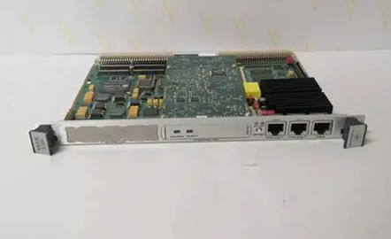
 MOTOROLA MVME172PA-652SE VME Embedded Controller
 -
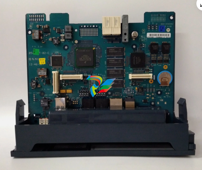 MOTOROLA FLN4234A ACE3600 CPU3680 Processor Module
 -
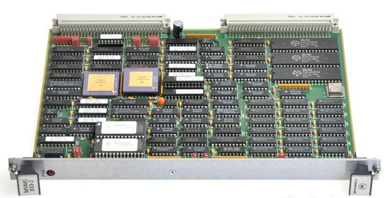 Motorola MVME333-2 Controller Communications Module Specs
 -
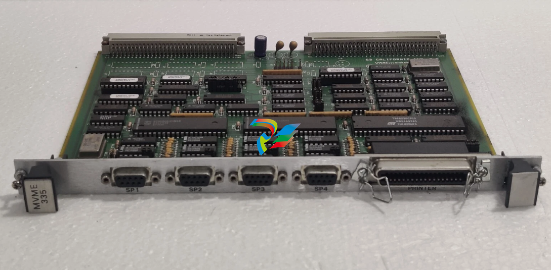 MOTOROLA MVME335 PCB California VME Module 0733500
 -
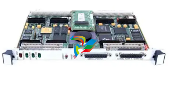
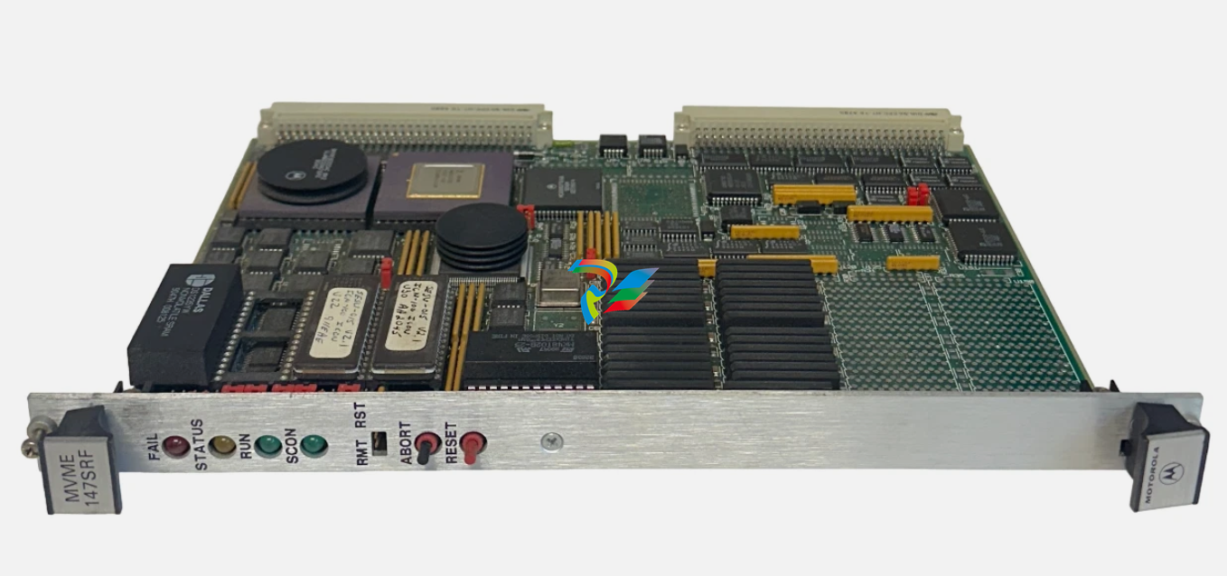 EMERSON MOTOROLA MVME-147SRF / MVME147SRF MPU VME MODULE
 -
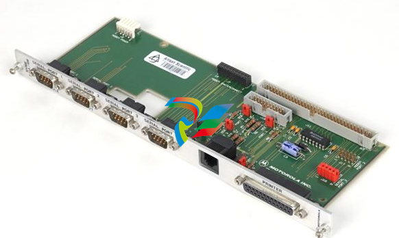
 MOTOROLA MVME705A Serial Transition Module
 -
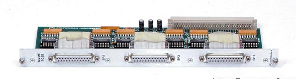 MOTOROLA MVME705B 6-Channel Serial Transition Module
 -
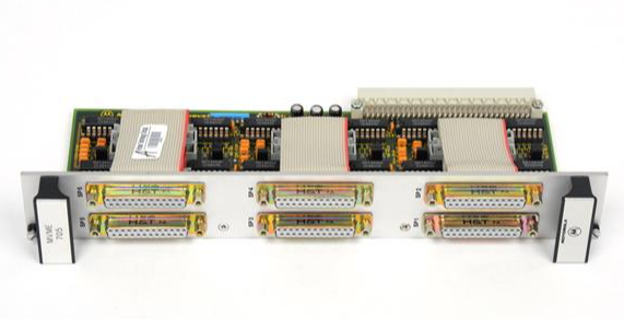
 MOTOROLA MVME712A MVME712AM I/O Transition Module
 -
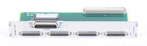 MOTOROLA MVME715P Rear Transition Module
 -
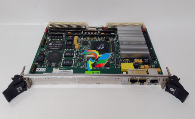
 MOTOROLA MVME172 VME Embedded Controller
 -
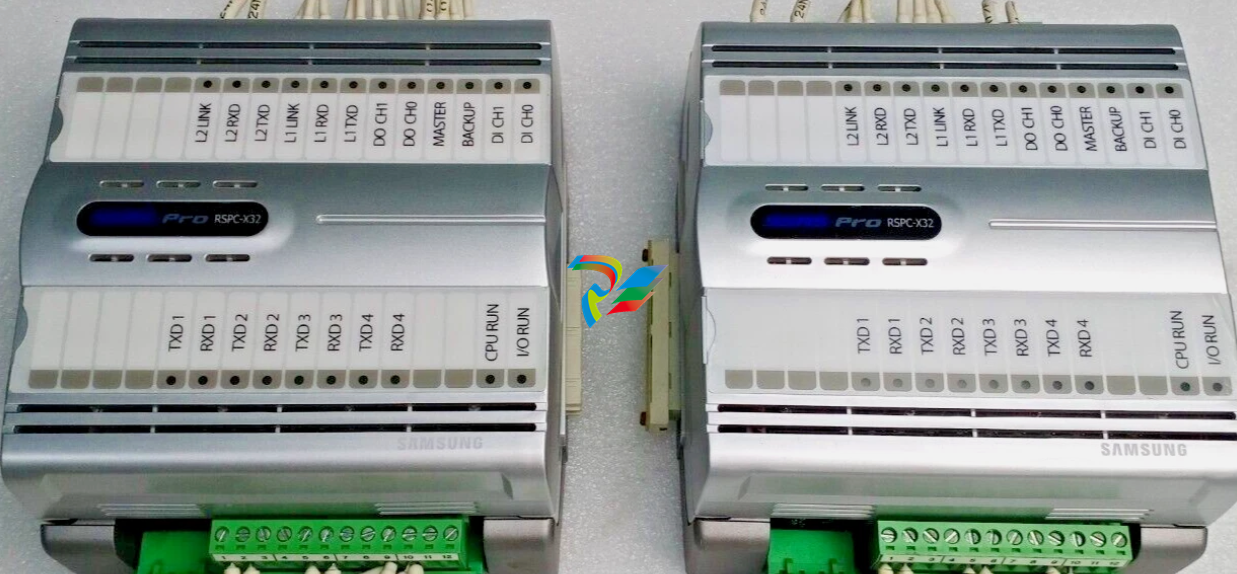 SAMSUNG SSAS-PRO RSPC-X32 ALARM AND MONITORING SYSTEM MODULE
 -
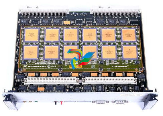
 MOTOROLA TMCP700 W33378F High-Performance Industrial Computing Module
 -
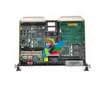
 MOTOROLA VME Single Board Computer MVME188A
 -
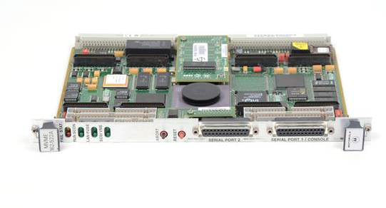
 MOTOROLA MVME162PA-344 High-Performance Embedded VME Controller
 -
 MOTOROLA FAB 0340-1049 High-Efficiency Intelligent Embedded Module
 -
 MOTOROLA 30-W2960B01A High-Performance Industrial Interface Module
 -
 MOTOROLA MVME712M Transition Module.
 -
 MOTOROLA MVME5500 Series VME Single-Board
 -
 MOTOROLA MVME300 High-Reliability GPIB VMEbus Controller
 -
 MOTOROLA CPCI-6020TM High-Performance CompactPCI Transition Module
 -
 MOTOROLA MVME162-210 Embedded Controller
 -
 MOTOROLA MVME162-522A 01-W3960B/61C Embedded Controller
 -
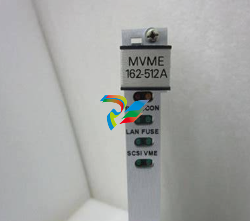 MOTOROLA MVME162-512A Embedded Controller
 -
 MOTOROLA MVME162-512 Embedded Controller
 -
 MOTOROLA MVME162-220 Embedded Controller
 -
 MOTOROLA MVME162-13 Embedded Controller
 -
 MOTOROLA MVME162-10 Embedded Controller
 -
 MOTOROLA MVME162-012 Embedded Controller
 -
 MOTOROLA MCP750 CompactPCI Host Slot Processor
 -
 Phoenix 2320267 QUINT-UPS/ 24DC/ 24DC/10/3.4AH - Uninterruptible power supply
 -
 Phoenix QUINT4-PS/3AC/24DC/40 - Power supply 2904623
 -
 Phoenix 2904622 QUINT4-PS/3AC/24DC/20 - Power supply
 -
 Phoenix 2905012 QUINT-PS/96-110DC/24DC/10/CO - DC/DC converter, protective coating
 -
 Phoenix 2905011 QUINT-PS/60-72DC/24DC/10/CO - DC/DC converter, protective coating
 -
 Phoenix 2904600 QUINT4-PS/1AC/24DC/5 - Power supply
 -
 Phoenix 2904603 QUINT4-PS/1AC/24DC/40 - Power supply
 -
 Phoenix 2904601 QUINT4-PS/1AC/24DC/10 - Power supply
 -
 Phoenix 2904602 QUINT4-PS/1AC/24DC/20 - Power supply
 -
 Phoenix QUINT-PS/60-72DC/24DC/10 - DC/DC converter 2905009
 -
 Phoenix QUINT-PS/96-110DC/24DC/10 - DC/DC converter 2905010
 -
 Phoenix QUINT-PS/3AC/24DC/20/CO - Power supply, with protective coating 2320924
 -
 Phoenix QUINT-PS/1AC/12DC/20 - Power supply 2866721
 -
 Phoenix 2320908 QUINT-PS/1AC/24DC/ 5/CO - Power supply, with protective coating
 -
 Phoenix 2866213 QUINT-BUFFER/24DC/20 - Buffer module
 -
 Phoenix 2866585 QUINT-DIODE/48DC/40 - Redundancy module, with protective coating
 -
 Phoenix 2320393 QUINT-BUFFER/24DC/24DC/40 - Buffer module
 -
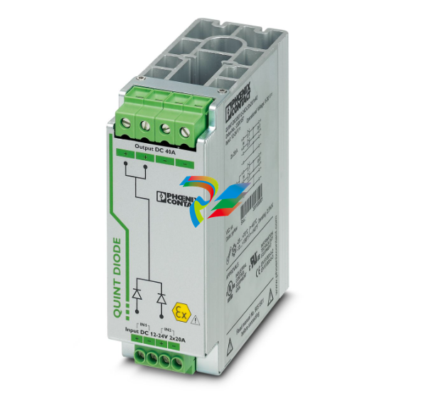 Phoenix 2320157 QUINT-DIODE/12-24DC/2X20/1X40 - Redundancy module
 -
 Phoenix 2907720 QUINT4-DIODE/48DC/2X20/1X40 - Redundancy module
 -
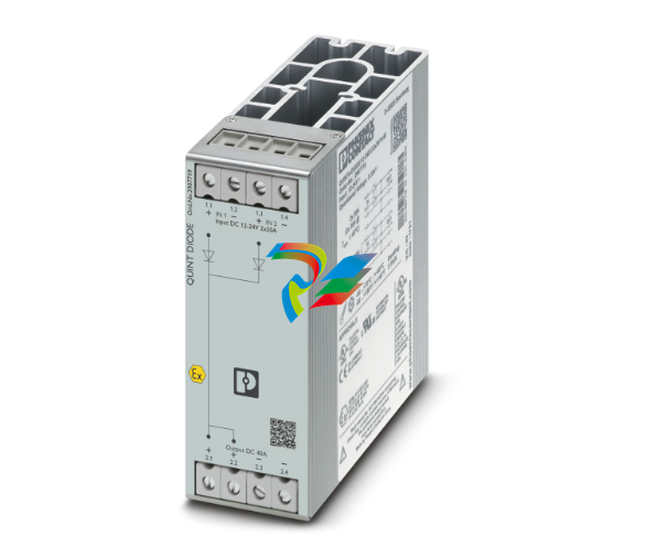 Phoenix 2907719 QUINT4-DIODE/12-24DC/2X20/1X40 - Redundancy module
 -
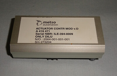 Metso A419471 High-Performance Analog Output Module
 -
 Applied Materials (AMAT) 0190-19092: High-Performance RF Match Controller Board
 -
 ABB UFC789AE101 3BHE014023R0101 High-Performance AC 800PEC Control Unit
 -
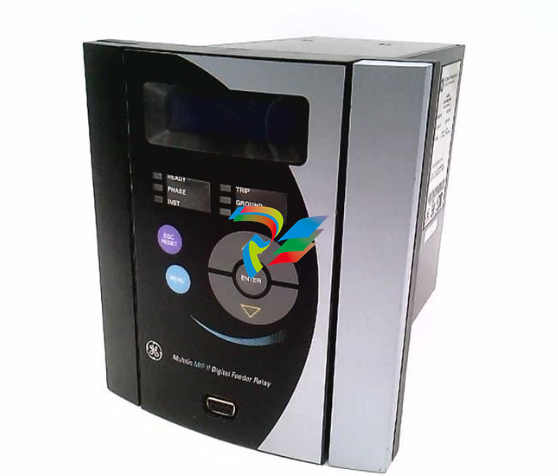 GE MIFIIPA55E20HI00 Multilin MIF II Digital Feeder Protection Relay
 -
 GE DS3815PAHB1A1A Speedtronic Mark IV Processor & Interface Board
 -
 GE DS3800NB1A Speedtronic Mark IV Power Supply / Regulator Board
 -
 GE DS3800HIOC Speedtronic Mark IV High-Level Input/Output Board
 -
 GE DS3800NHVG Speedtronic Mark IV High-Voltage Gate Driver Board
 -
 ABB 1TGE120011R1010 MC M117 KIT 24VDC CMMB+PTC
 -
 Woodward 5448-897 Current Differential Protection Relay
 -
 GE IS220PAOCH1BE Mark VIe Analog I/O Module
 -
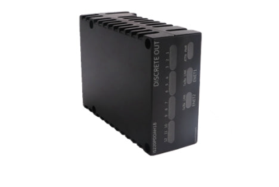 GE IS220PDOAH1B Mark VIe Discrete Output (PDOA) I/O Pack
 -
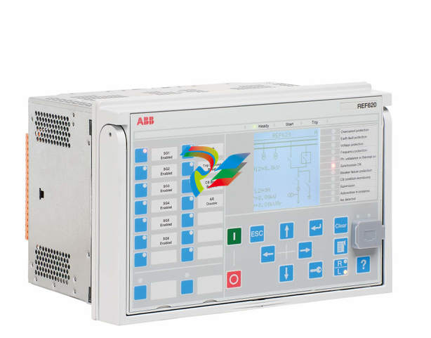 ABB Feeder Protection and Control REF620E_1G NBFNAAAAAABC6BBN11G
 -
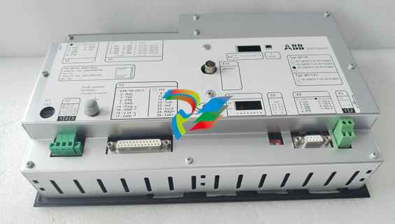 ABB MT-91-ARCFPA High-Precision Tension Control Interface Module
 -
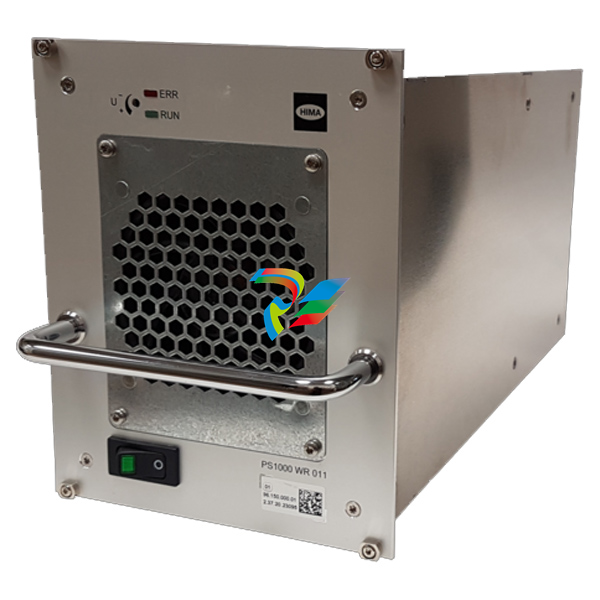 HIMA PS1000/230010 982200080 high-performance power supply module
 -
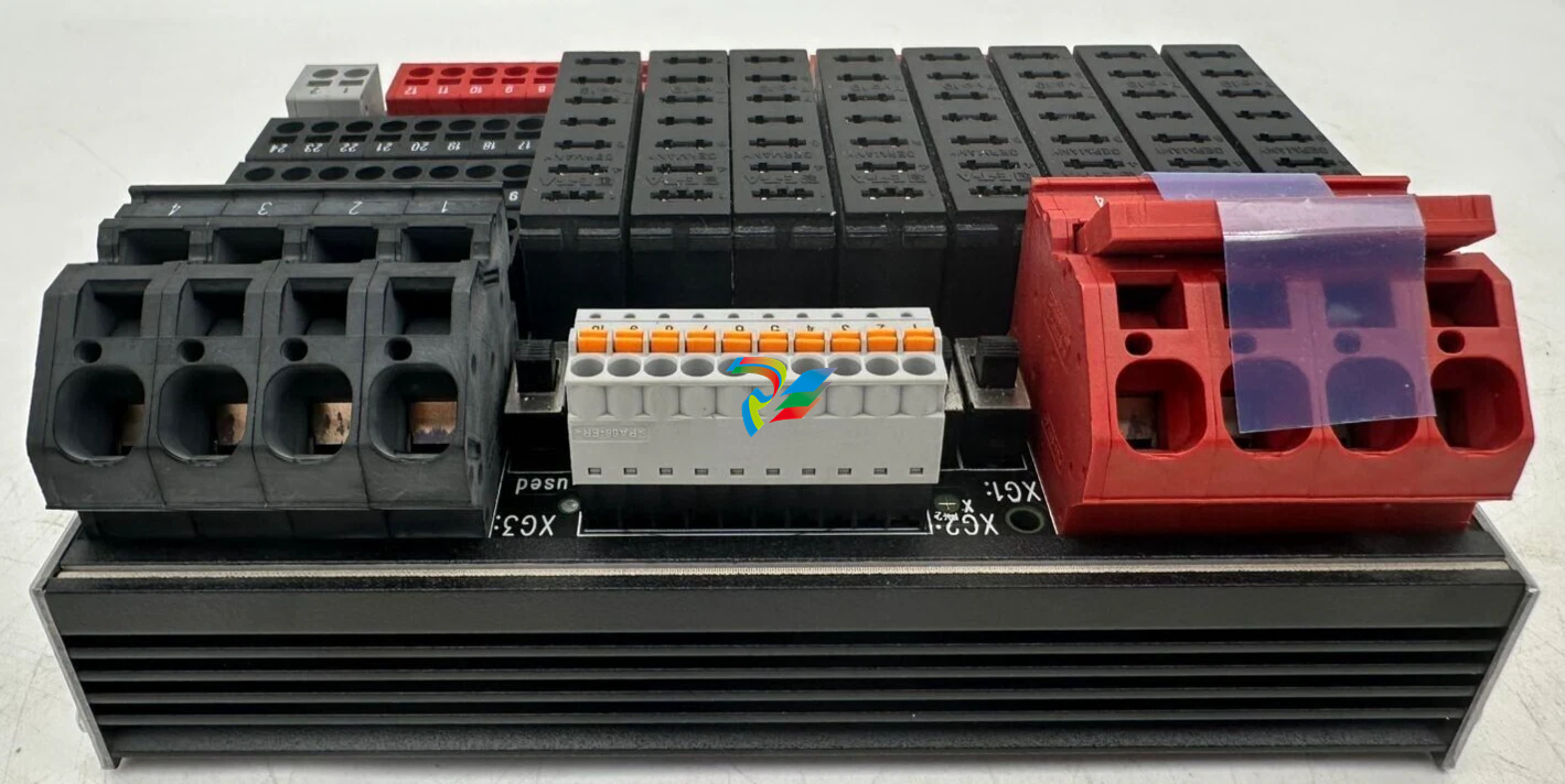 HIMA H7202 Distribution Fuse Board / Infeed Board
 -
 HIMA F60DIO24/1601 Safety-Related Controller
 -
 HIMA F60DO801 Safety-Related Controller
 -
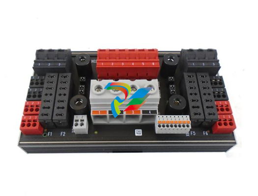 HIMA H7201 Line fuse board
 -
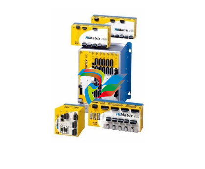
 HIMA HIMatrix ELOP II 892042336 Version V5.6 Build 1501.9810 IV1
 -
HIMA HIMatrix SILworX 504110 895400001
-
 HIMA HIMatrix SILworX 504111 895210001
 -
 HIMA OPC DA Server 892042400 Version 3.56.4
 -
 HIMA OPC Alarm & Event Server (892042420) Version 4.1.3
 -
 HIMA OPC Alarm & Event Server (892042420) Version 4.0.5
 -
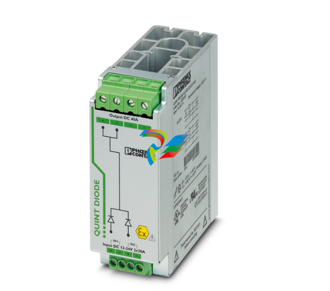 Phoenix QUINT-DIODE/12-24DC/2x20/1x40 2320157 Redundancy module
 -
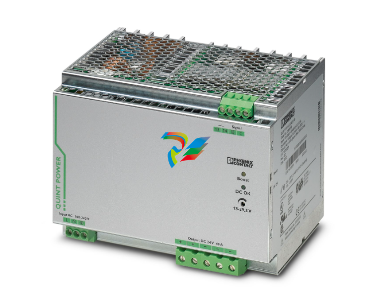 Phoenix QUINT-PS/1AC/24DC/40 2866789 Power supply
 -
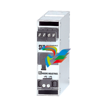 Moore SIY/PRG/4-20MA/10-42DC SIY PC Programmable Signal Isolator and Converter
 -
.png) Motorola 01-W3394F-03F Communication Interface Module
Motorola 01-W3394F-03F Communication Interface Module -
 Motorola AP-4 256 MByte 01-W3839F-07A Communication Module
 -
MOTOROLA MVME2432 01-W3394F-03C VME Processor Module
-
 MOTOROLA PCE I 01-W3839F-07A VME Processor Module
 -
.png) Motorola HPR431 / SYS431 / SYS443 / MFT543 Component Assembly
Motorola HPR431 / SYS431 / SYS443 / MFT543 Component Assembly -
Motorola AP-4 01-W3394F-03G Communication Interface Module
-
 Emerson 01-W3878F-02D DeltaV M-Series I/O Module
 -
 ICS Triplex Trusted T8232 Power Pack Module
 -
 ALFA LAVAL AAL7000 OXYGEN ANALYSER V0.1
 -
Alstom MPM123 Measurement and Protection Module
-
 Honeywell 5701 CONTROL SYSTEM
 -
.png) KONGSBERG MRU-E-JB1 Host machine
KONGSBERG MRU-E-JB1 Host machine -
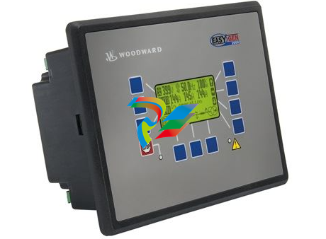
 Woodward easYgen-3200-1/P1 8440-2049
 -
 Woodward easYPROTEC-1410-7 8441-1161 8441-1160
 -
 Woodward MFR300-71M/K45 8444-1111 8444-1112
 -
 Woodward MFR300-75M 8444-1107 8444-1108 8444-1109
 -
 Woodward MFR300-71M/K42 8444-1104
 -
 Woodward MFR300 75M/SU03, Transducer 8444-1093 8444-1094 8444-1095
 -
 Woodward MFR300-71M 8444-1091 8444-1092
 -
Woodward MFR300-15M 8444-1090 8444-1089
-
 Woodward MFR300-11M 8444-1071 8440-1089
 -
 Woodward MFR500-6M/WK0400 + DPC USB 8444-1070
 -
 Woodward MFR300-15M 8444-1064
 -
Woodward SPM-D2-1040B/NYB 8440-2189
-
Woodward SPM-D2-1010B/NYB 8440-2177
-
 Woodward SPM-D2-10B/PSY5-FU-D 8440-2170
 -
 Woodward SPM-D2-1040B/XN analog speed/voltage bias 8440-2190
 -
Woodward MFR300-71M 8444-1063
-
SPM-D2-1010B/X analog speed/voltage bias 8440-2168
-
 Woodward SPM-D2-1040B/X analog speed/voltage bias 8440-2171
 -
 Woodward SPM-D2-1010B/N wide range power supply 8440-2174
 -
Woodward SPM-D2-1040B/N wide range power supply 8440-2175
-
 Woodward SPM-D2-1010B /110VAC sensing 8440-2166
 -
Woodward SPM-D2-1040B /400VAC sensing 8440-2164
-
 Woodward DTSC-200A 8440-2297
 -
 Woodward DTSC-200-55B/K38 8440-2155
 -
Woodward DTSC-200-51B 8440-1867 8440-1868
-
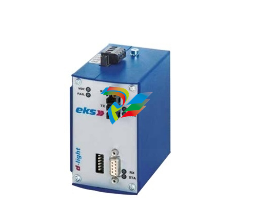 Woodward 8445-1049 8445-1048 Converter, 1x FO to CAN
 -
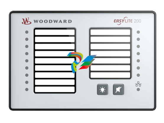 Woodward easYlite-200 8446-1007 LED Lamp Expansion Module
 -
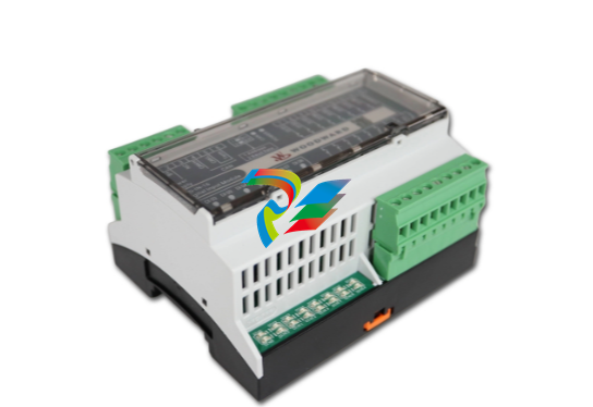 Woodward IKD-OUT-16 16 DO Expansion Card 8440-2306
 -
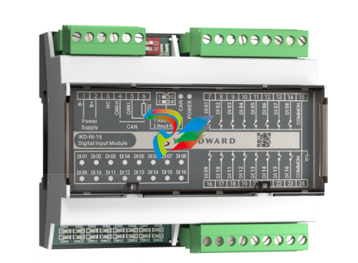 Woodward IKD-IN-16 16 DI Expansion Card 8440-2307
 -
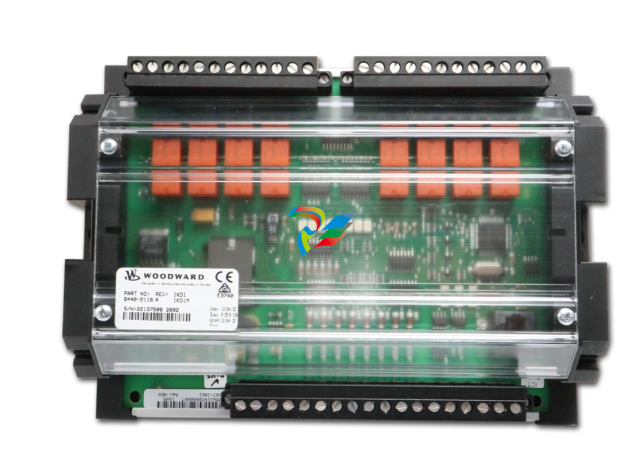 Woodward IKD1M 8 DI/8 DO Expansion Card 8440-2116
 -
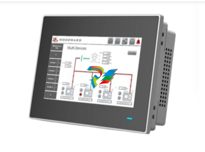 Woodward easYview-07-30 8446-1071
 -
 Woodward easYFLEX-3400XT-P2 (GAP) 8440-2217
 -
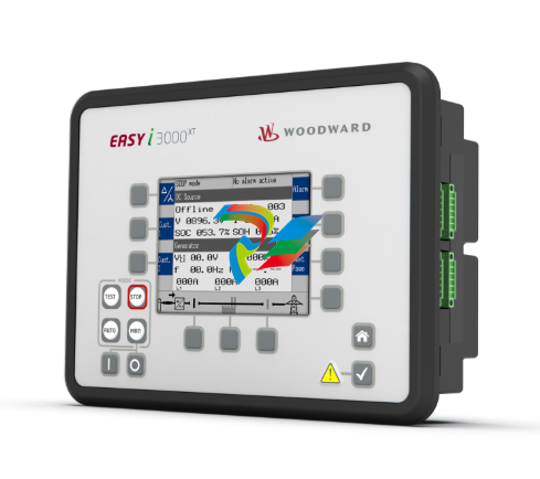
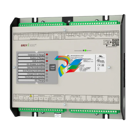
Woodward easY-I-3400XT-P1 8440-2293
-
 Woodward easY-I-3500XT-P1 8440-2292
 -
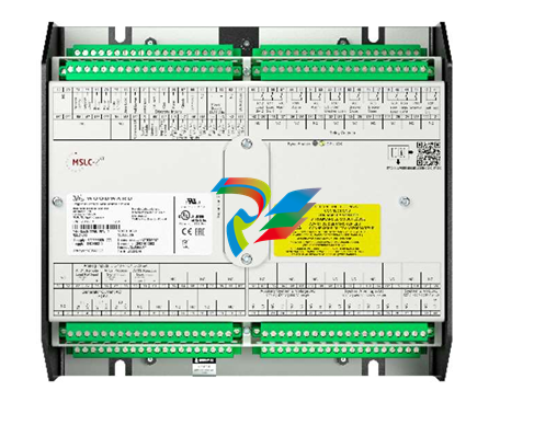 Woodward MSLC-2XT 8440-2298 Master Synchronizer and Load Control
 -
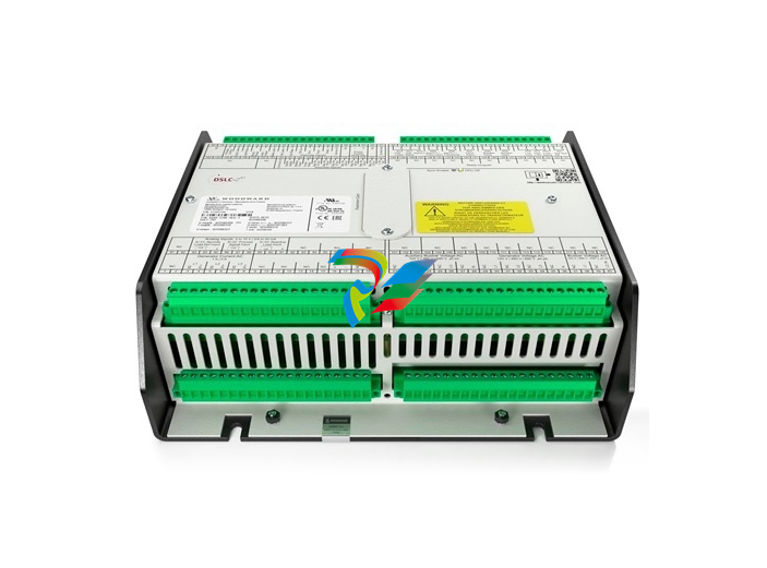 Woodward DSLC-2XT 8440-2299 Digital Synchronizer and Load Control
 -
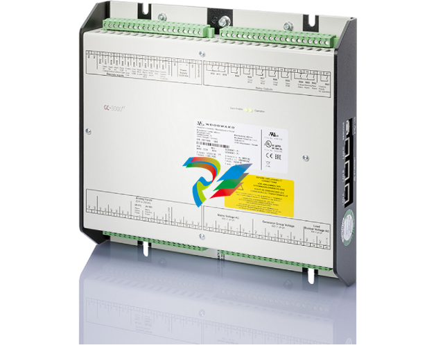 Woodward: GC-3400XT-P1 8440-2267 Group Controller
 -
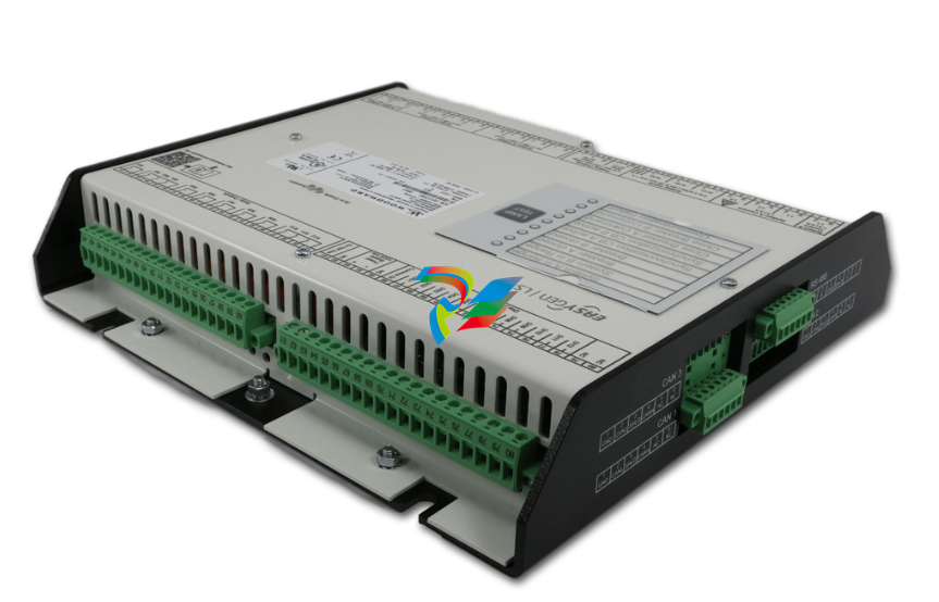
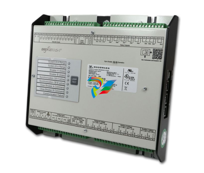 Woodward: LS-612XT-P2 8440-2317
 -
 Woodward: CONTROL-LS-612XT-P1,8440-2222 Cabinet back mounting


