
parkerQUICK START MANUAL VM600 machinery protection system (MPS)
dangerous and may damage the equipment or result in injury.
Read the following recommendations carefully before handling electronic
circuits, printed circuit boards or modules containing electronic
components
INSTALLATION
This chapter provides a brief overview on the installation of VM600 machinery protection
system (MPS) hardware. Information is provided on unpacking, installing a rack, connecting
power, connecting cards and software configuration.
NOTE: For further information on installing a VM600 machinery protection system (MPS),
refer to the VM600 machinery protection system (MPS) hardware manual.
1.1 Unpacking and inspecting
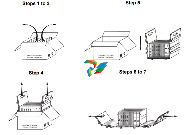
The procedure for unpacking VM600 MPS hardware is shown in Figure 1-1 and described
below:
Figure 1-1: Procedure for unpacking and inspecting VM600 MPS hardware
Step 1: Place the outer box on a flat surface with the arrows on the side of the box
pointing upwards.
Step 2: Open the outer box along the tape using a pair of scissors.
Step 3: Pull the handles of the inner box outwards to a vertical position.
Step 4: Gently lift the inner box vertically out of the outer box using the handles of the
inner box.
Step 5: Place the inner box on a flat surface.
Step 6: Open the inner box using the handles.
Step 7: Inspect the VM600 MPS hardware to ensure that no damage has occurred
during delivery
If damage has occurred to VM600 MPS hardware during delivery, please contact
your nearest Meggitt representative.
1.2 System overview
The VM600 machinery protection system (MPS) is a digital machinery protection system
designed for use in industrial applications. It is intended primarily for vibration monitoring to
assure the protection of rotating machinery as used in, for example, the power generation,
petro-chemical and petroleum industries as well as in marine related applications.
The VM600 series of machinery protection and condition monitoring systems from Meggitt’s
Vibro-Meter® product line are based around a 19" rack containing various types of cards,
depending on the application.
There are basically two types of system:
• VM600 machinery protection system (MPS – 1U or 6U rack).
• VM600 condition monitoring system (CMS – 1U or 6U rack).
It is also possible to integrate MPS and CMS hardware into the same VM600 rack (ABE04x).
NOTE: This manual describes machinery protection system (MPS) hardware only.
Further information on condition monitoring system hardware can be found in the
VM600 condition monitoring system (CMS) hardware manual.
In its most basic configuration, a VM600 machinery protection system (MPS) consists of the
following hardware:
1- VM600 rack: 19" system rack x 6U (ABE04x) or 19" slimline rack x 1U (ABE056)
NOTE: ABE04x refers to both the ABE040 and ABE042, which are identical apart from the
position of the rack mounting brackets.
2- RPS6U rack power supply (ABE04x only)
When an AC-input version of the RPS6U is installed in a VM600 rack, the optional ASPS
auxiliary sensor power supply can be used to replace external power supplies such as
the APF19x 24 VDC power supplies.
3- MPC4 machinery protection card
4- IOC4T input/output card for the MPC4
5- AMC8 analog monitoring card
6- IOC8T input/output card for the AMC8.
The MPC4 and IOC4T cards form an inseparable card pair and one cannot be used without
the other. These cards are used primarily to monitor vibration for the purposes of machinery
protection.
Similarly, the AMC8 and IOC8T cards form an inseparable card pair and one cannot be used
without the other. These cards are used primarily to monitor quasi-static parameters such as
temperature, fluid level or flow rate for the purposes of machinery protection.
In general, a VM600 rack used for machinery protection can contain:
• Only MPC4 / IOC4T card pairs
• Only AMC8 / IOC8T card pairs
• A combination of MPC4 / IOC4T and AMC8 / IOC8T card pairs.
Depending on the application, the following type of cards can also be installed in the VM600
rack (ABE04x or ABE056):
7- RLC16 relay card (16 relays) and IRC4 intelligent relay card (eight relays combined as
either 4 DPDT or 8 SPDT).
All the above items can be used to make a stand-alone MPS system, that is, one that is not
connected to a network.
A networked version of the MPS will in addition contain the following hardware in the VM600
rack (ABE04x):
8- CPUM modular CPU card
9- IOCN input/output card for the CPUM.
Depending on the application (and irrespective of whether the rack is used in a stand-alone
or a networked configuration), one or more of the following power supplies can be used
outside a VM600 rack (ABE04x):
• APF19x 24 VDC power supplies
• Any equivalent low-noise power supply provided by the customer.
These devices must be used for GSI1xx galvanic separation units, GSV safety barriers and
transducer and signal conditioner front-ends having a current requirement greater than
25 mA. They will often be mounted in the cubicle in which the rack is installed.
NOTE: Auxiliary sensor power supplies (ASPSs) installed in a VM600 rack (ABE04x)
perform the same function as external power supplies such as the APF19x 24 VDC
power supplies. That is, they are used to power external hardware such as GSI
galvanic separation units or signal conditioners that require more power than can
-
 Applied Materials (AMAT) 0190-04098 | 5.X Factory Interface I/O Distribution Board
 -
 Applied Materials (AMAT) 0190-03705 | MF Producer SE/E Interlock Module
 -
 Applied Materials (AMAT) 0190-02748 | Flex Scanner Transition Module
 -
 Applied Materials (AMAT) 0190-02362 | Mainframe Interlock 1 Relay Module
 -
 Applied Materials (AMAT) 0190-01227 | Intelligent Motor Control OMS Board
 -
 Applied Materials (AMAT) 0190-00318 | VME 486 Video Controller
 -
 Applied Materials (AMAT) 0130-14007 | Advanced RF Signal Assembly
 -
 Applied Materials (AMAT) 0130-14005 | RF Cable/Interface Assembly
 -
 Applied Materials (AMAT) 0130-01218 | High-Efficiency RF Interface Controller
 -
 Applied Materials (AMAT) 0110-77040 | Head Pneumatic Controller
 -
 Applied Materials (AMAT) 0110-00077 | Precision Control Module
 -
 AMAT 0101-57015 high-performance Next-Generation Deflection Amplifier Board
 -
 AMAT 0100-77040 critical Head Pneumatic Controller Board
 -
 AMAT 0100-76291 Data Buffer / Memory Expansion Interface
 -
 AMAT 0100-76290 Advanced I/O Interface Board
 -
 AMAT 0100-76269 Control Board / Interface Module
 -
 AMAT 0100-71462-01 high-performance Process Controller PCB
 -
 AMAT 0100-71171 Chamber Interlock Control PCB
 -
 AMAT 0100-71154 Semiconductor Circuit Board / Electronic Group Card
 -
 AMAT 0100-70034 PCB Assembly (PCBA) for Endpoint VGA I/O Interconnect.
 -
 AMAT 0100-38032 ESC (Electrostatic Chuck) Controller PCB
 -
 AMAT 0100-36035 DPS Source Match / Seriplex I/O Distribution PCB
 -
 AMAT 0100-35231 Seriplex I/O Distribution Module
 -
 AMAT 0100-35217 TC Amp Interlock PCB Module
 -
 AMAT 0100-35065 High-Precision Serial Isolator PCB
 -
 AMAT 0100-35054 Advanced Chamber Interface Module
 -
 AMAT 0100-20453 DeviceNet Digital I/O Interface Board
 -
 AMAT 0100-20100 High-Performance Semiconductor Component
 -
 AMAT 0100-20068 Precision CCD Image Control Board
 -
 AMAT 0100-20064 Advanced Semiconductor Control Module
 -
Applied Materials (AMAT) 0100-20018 Advanced Communication Interface Module
-
 Applied Materials (AMAT) 0100-20016 High-Performance Interface and Control Module
 -
 Applied Materials (AMAT) 0100-20003 Digital I/O (DI/DO) Interface Board
 -
 Applied Materials (AMAT) 0100-20001 System Electronics Interface (SEI) / PCB Assembly
 -
 Applied Materials (AMAT) 0100-11030 Chamber Hardware / Gas Distribution Component
 -
 Applied Materials (AMAT) 0100-11022 Semiconductor Board Card
 -
 Applied Materials (AMAT) 0100-11018 Advanced Interface Control Module
 -
 Applied Materials (AMAT) 0100-11001 Precision Analog Output Board
 -
 Applied Materials (AMAT) 0100-11000 High-Precision Analog Input Board
 -
 Applied Materials (AMAT) 0100-09237 Advanced Signal Interface Module
 -
 Applied Materials (AMAT) 0100-09204 Advanced Digital Interface Control Board
 -
 Applied Materials (AMAT) 0100-09172 High-Density Digital I/O Control Board
 -
 Applied Materials (AMAT) 0100-09137 High-Performance VME Control Module
 -
 Applied Materials (AMAT) 0100-09054 Precision Analog Input Board
 -
 Applied Materials (AMAT) 0100-09029 Turbo Interconnect Interface Module
 -
 AMAT 0100-03391 Precision Semiconductor Control
 -
 AMAT 0100-01984 | VME System Interface & Logic Controller Board
 -
 AMAT 0100-01363 | VME Intelligent System Control & I/O Board
 -
 AMAT 0100-01321 | VME DeviceNet Scanner / Interface Board
 -
AMAT 0100-00793 | VME Multi-Channel Interface & Logic Board
-
 AMAT 0100-00689 | VME PCB Power Module
 -
 AMAT 0100-00580 | VME Intelligent System Controller Board
 -
 AMAT 0100-00523 | VME Multi-Channel Analog-to-Digital (A/D) Board
 -
 AMAT 0100-00493 | VME Multi-Function System Controller Board
 -
 AMAT 0100-00398 | VME Interface System Control Board
 -
 AMAT 0100-00369 | VME 12-Channel High-Speed Stepper Motor Controller
 -
 AMAT 0100-00196 | VME System Mainframe CPU Controller Board
 -
 AMAT 0100-00169 | VME 12-Channel Stepper Motor Controller Board
 -
 AMAT 0100-00162 | VME Dual Channel Serial Communication Board
 -
 AMAT 0100-00137 | VME Stepper Motor Controller Interface Board
 -
 AMAT 0100-00075 | VME Digital Input/Output (DI/O) Interface Board
 -
 AMAT 0100-00007 VME Analog Input/Output Interface Board
 -
 AMAT 0100-00002 | VME Slave I/O Interface PCB
 -
 AMAT 0090-05596 High-Voltage DC Power Cable Assembly
 -
 AMAT 0090-01809 | High-Performance RF Power Cable Assembly
 -
 AMAT 0010-29958 | CCM HART 3 Mainframe Control Assembly
 -
 AMAT 0010-20003 System Controller Card Cage Assembly
 -
.png) AMAT 0010-11239 PVD High-Voltage Power Interface Assembly
AMAT 0010-11239 PVD High-Voltage Power Interface Assembly -
 AMAT 0010-09416 RF Matching Network Assembly
 -
 AMAT 0010-00019 Analog Power Supply Assembly
 -
 AMAT AS00009-02 (31-000-00940) | Precision Semiconductor Component
 -
 AMAT 0010-00028 Power Supply Module
 -
 AMAT 0330-1586A Serial Communication PCB
 -
 AMAT 0190-09690 Seriplex SENSORbus SPX-MUXADIO-001
 -
 AMAT 0190-04397 DeviceNet I/O Interface Board
 -
 AMAT 0190-02506 DeviceNet I/O Interface Card
 -
 AMAT 0090-00475 Seriplex 210 MUXADIO
 -
 AMAT 410-0198-1 Multi-Output Switching Power Supply
 -
 AMAT 0100-20458 high-reliability Configurable Interlock Personality Board
 -
 AMAT VAS104350-0415 Gasline Heater Control Unit
 -
 AMAT VME6U1V2 VMEbus Backplane Interface Module
 -
AMAT 0920-01070 high-performance RF Power Generator
-
 AMAT 0090-76133A VME Single Board Computer (SBC)
 -
 AMAT 0190-24115 DeviceNet I/O Interface Card
 -
 AMAT 0190-37607 Backplane / Base Board Assembly
 -
 AMAT 0190-32372 Analog Input/Output (I/O) Board
 -
 AMAT 0190-09956 Loadlock Interface PCB Base Assembly
 -
 AMAT 0190-07908 four-channel DeviceNet Interface Card
 -
 AMAT 0190-07905 (UPS) control board
 -
 AMAT 0190-07502 Precision Controller / Interface Board
 -
 AMAT 0190-03680 I/O Backplane
 -
 AMAT 0190-02200 Water Leak Detection Control Board
 -
 AMAT 0100-76124 Digital I/O Board Assembly
 -
 AMAT 0100-35563 Leak Detector Configuration PCB
 -
 AMAT 0100-35250 Chamber Interface DPS Centura PCB
 -
 AMAT 0100-35124 Seriplex I/O Distribution Board
 -
 AMAT 0100-35058 Loadlock Interlocks PCB
 -
 AMAT 0100-20213 RF Match Detector PCB
 -
 AMAT 0100-20063 Interface PCB Assembly
 -
 AMAT 0100-09225 TC AMP/INTERLOCK PCB
 -
 AMAT 0100-09153 Gas Panel Interface PCB
 -
 AMAT 0100-09127 Loader Interconnect Board
 -
 AMAT 0100-09009 Buffer I/O PCB Card
 -
 AMAT 0100-02813 Signal Conditioning Board
 -
 AMAT 0100-01911 AC Gas Heater Control Board
 -
 AMAT 0100-01708 Pedestal Integration PCB
 -
 AMAT 0100-00658 300mm RTP Controller Distribution PCB
 -
 AMAT 0100-00582 Gas Panel Controller Backplane
 -
 AMAT 0100-00049 Analog Signal Conditioner
 -
 AMAT 0100-00008 Control Interface Module
 -
 AMAT 0090-03402 DC Power Supply / Power Module
 -
 AMAT 0090-01248 DC Power Supply / Power Module
 -
 AMAT 0090-76109 RF Matching / Capacitor Assembly
 -
 AMAT 0101-57106 Substrate Voltage Board
 -
 AMAT 0101-57014 Deflection-Amplifier PCB
 -
 AMAT 0101-57012 AKT Column Control PCB (COL-C 50-10)
 -
 AMAT AKT 0241-58482 PCB
 -
 AMAT 0241-58255 REV05 PCB
 -
 AMAT 0161-57042 AKT framework
 -
 AMAT 0101-57196 electronic control board
 -
 AMAT 0101-57178 Digital Input / Interface PCB
 -
 AMAT 0101-57162 electronic control board
 -
 AMAT 0101-57127 P-DRV (Power Driver Board)
 -
 AMAT 0101-57126 D-AMP 50-06 (Digital/Analog Amplifier)
 -
 AMAT 0101-57125 AKT COL-C Communication Board
 -
AMAT 0101-57120 D-OUT 50-32 (Digital Output Board)
-
 AMAT 0101-57112 D-IN 50-32 (Digital Input Board)
 -
 AMAT 0101-57102 electronic control board


