
Woodward easYgen-3000 Genset Control for
easYgen-3000
Genset Control for
Multiple Unit Operation

The easYgen-3000 is a control unit for genset management applications. The numerous inputs and outputs,
along with a modular software structure, permit you to use the easYgen-3000 for a wide range of applications
with only a single part number. This includes stand-by, AMF, peak shaving, import-export, cogeneration or
distributed generation, among others. Also the easYgen-3000 is compatible for island, island parallel, mains
parallel and multiple unit mains parallel operations.
The easYgen-3000 is able to control up to 32 gensets connected in a network with automatic sequencing.
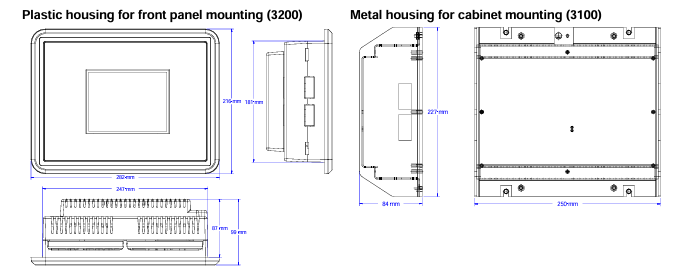
The easYgen-3000 is available in two variants, the easYgen-3100 for cabinet back panel installation, and the
easYgen-3200 with graphical display and soft keys for front panel mounting.
FlexAppTM – This feature provides the tools to easily configure the number of operated breakers: None, GCB,
GCB and MCB.
LogicsManagerTM – Woodward's LogicsManager software enables to change the operation sequences and
adapt them to specific needs. The LogicsManager accomplishes this by monitoring a range of measuring val
ues and internal states, which are combined logically with Boolean operators and programmable timers. This
enables to create and/or modify control and relay functions.
FlexInTM – The analog inputs are configurable to operate with VDO, resistive, and/or 0 to 20 mA senders.
Flexible Outputs – Speed and voltage bias outputs are configurable to function with all speed governors and
voltage regulators. The outputs can also be used as freely scalable outputs (e.g. for driving external meters).
FlexCANTM – Advanced network interfaces ensure unsurpassed control performance – from engine control up
to total plant operation. The easYgen-3000 is capable of working with all common industrial interfaces, includ
ing CAN, RS-232. and RS-485. The multiple communication protocols permit the easYgen-3000 to communi
cate with a vast majority of engine control units (ECUs), external I/O boards, PLCs, and modems. CANopen,
J1939. Modbus RTU, and Modem protocols are supported.
DynamicsLCDTM – The adaptive and interactive 5.7", 320x240 pixel graphical LC display with soft keys and a
clear menu structure ensures intuitive user operation and navigation.
Features
• Operation modes: Auto, Stop, Manual, and Load/No Load test modes via discrete input possible
• Breaker control: Slip frequency / phase matching synchronization, open-close control, breaker monitoring
• Load transfer features: open / closed transition, interchange, soft loading / soft unloading, mains parallel
• Process and load-dependent start/stop logic for diesel and gas engines programmable for spinning or system
reserve with fixed or dynamic priorities.
• Real and reactive power load sharing with up to 32 units
• Remote control via interface and discrete/analog inputs for adjusting speed, frequency, voltage, power, reactive
power, and power factor set points
• Complete integrated engine and generator protection as well as mains monitoring features
• Freely configurable PID controllers for various control purposes, such as heating circuit control (CHP applica
tions), water level, fuel level, or pressure and/or other process values
• Special Scania S6. MTU ADEC, Volvo EMS2 & EDC4. Deutz EMR2. MAN MFR/EDC7. SISU EEM and Wood
ward EGS02 ECU support (depending on Package)
• Counters for operating hours / engine starts / maintenance / active energy / reactive energy
• Configurable trip levels / delay timers / alarm classes for monitoring and protective functions
• Clear text display and evaluation of up to 100 J1939 analog values
• Discrete and analog I/O expansion board connectivity (Woodward IKD 1 or Phoenix Contact IL series)
• Front panel and PC configurable (ToolKit software)
• Multi-level password protection for access via HMI or interface
• Multi-lingual capability (English, German, French, Spanish, Chinese, Japanese, Italian, Portuguese, Turkish, Russian)
• Peak shaving operation
• Stand-by operation
• AMF operation
• Cogeneration (CHP)
• Isolated & mains parallel
operation
• Import/export control
• Soft loading features
• Open/closed transition
• Load sharing and load
dependent start/stop for
up to 32 units
• Programmable operation
sequences
• Multi-lingual capability
• CANopen / J1939 ECU
Control
• Modbus RTU Protocol
• CE marked
• UL/cUL Listing
• LR & ABS Marine Ap
provals
• Event recorder (300 events, FIFO) with real time clock
Power supply .......................................................... 12/24 Vdc (8 to 40 Vdc)
Intrinsic consumption .................................................................. max. 17 W
Ambient temperature (operation) ....................... -20 to 70 °C / -4 to 158 °F
Ambient temperature (storage) ........................ -30 to 80 °C / -22 to 176 °F
Ambient humidity ...................................................... 95 %, non-condensing
Voltage ............................................................................................... ( /Δ)
100 Vac [1] Rated (Vrated) ............................................ 69/120 Vac
Max. value (Vmax) ........................................... 86/150 Vac
Rated surge volt.(Vsurge) .................................................... 2.5 kV
and 400 Vac [4] Rated (Vrated) .......................................... 277/480 Vac
Max. value (Vmax) ......................................... 346/600 Vac
Rated surge volt.(Vsurge) .................................................... 4.0 kV
Accuracy .......................................................................................... Class 1
Measurable alternator windings ..................... 3p-3w, 3p-4w, 1p-2w, 1p-3w
Setting range ..................... primary .................................50 to 650.000 Vac
Linear measuring range .............................................................. 1.25×Vrated
Measuring frequency................................................50/60 Hz (40 to 85 Hz)
High Impedance Input; Resistance per path ....... [1] 0.498 MΩ, [4] 2.0 MΩ
Max. power consumption per path ................................................ < 0.15 W
Current (Isolated) Rated (Irated) .............................. [1] ../1 A or [5] ../5 A
Linear measuring range ....................................................... Igen = 3.0×Irated
Imains/ground = 1.5×Irated
Setting range .......................................................................... 1 to 32.000 A
Burden .......................................................................................... < 0.15 VA
Rated short-time current (1 s) ................................ [1] 50×Irated, [5] 10×Irated
Power .........................................................................................................
Setting range .......................................................... 0.5 to 99.999.9 kW/kvar
Discrete inputs .............................................................................. isolated
Input range ............................................................. 12/24 Vdc (8 to 40 Vdc)
Input resistance .............................................................. approx. 20 kOhms
Measuring
Generator voltage (3-phase/4-wire)
Generator current (3x true r.m.s.)
Mains voltage (3-phase/4-wire)
Mains or ground current (1x true r.m.s.) #1
Busbar voltage (1-phase/2-wire)
Control
Breaker control logic (open and closed transition) FlexAppTM 2 2 2 2
Automatic, Manual, Stop, and test operating modes
Single and multiple-unit operation
Mains parallel multiple-unit operation (up to 32 units) #2
AMF (auto mains failure) and stand-by operation
Critical mode operation
GCB and MCB synchronization (slipping / phase matching)
Interchange (import / export control)
Load-dependent start/stop
n/f, V, P, Q, and PF remote control via analog input or interface
Load/var sharing for up to 32 gensets
Freely configurable PID controllers - 3 - 3
HMI
Soft keys (advanced LC display) DynamicsLCDTM - -
Start/stop logic for diesel / gas engines
Counters for operating hours / starts / maintenance / active/reactive energy
Configuration via PC #3
Event recorder entries with real time clock (battery backup) 300 300 300 300
Protection ANSI#
Generator: voltage / frequency 59 / 27 / 81O / 81U
Generator: overload, reverse/reduced power 32 / 32R / 32F
Generator: unbalanced load 46
Generator: instantaneous overcurrent 50
Generator: time-overcurrent (IEC 255 compliant) 51
Generator: ground fault #4
50G
Generator: power factor 55
Generator: rotation field
Engine: overspeed / underspeed 12 / 14
Engine: speed / frequency mismatch
Engine: D+ auxiliary excitation failure
Mains: voltage / frequency 59 / 27 / 81O / 81U
Mains: phase shift / rotation field 78 /
I/Os
Speed input (magnetic / switching; Pickup)
Discrete alarm inputs (configurable) 10 10 10 10
Discrete outputs (configurable) LogicsManagerTM max. 12 max. 12 max. 12 max. 12
External discrete inputs / outputs via CANopen (maximum) 16 / 16 32 / 32 16 / 16 32 / 32
Analog inputs #5 (configurable) FlexInTM 3 3 3 3
Analog outputs (+/- 10V, +/- 20mA, PWM; configurable) 2 2 2 2
External analog inputs / outputs via CANopen (maximum) - 16 / 4 - 16 / 4
Display of J1939 analog values (number of SPNs) 16 - 16 -
Display and evaluation of J1939 analog values (supported SPNs) - 100 - 100
CAN bus communication interfaces #6 FlexCANTM 2 2 2 2
RS-232/485 Modbus RTU Slave interface(s) 1 / 1 1 / 1 1 / 1 1 / 1
Listings/Approvals
UL Listing
cUL Listing
LR & ABS Marine Approval
CE Marked
Part Numbers
1A CT inputs / front panel mounting with display #7 P/N 8440- - - 1816 1842
5A CT inputs / front panel mounting with display #7 P/N 8440- - - 1831 1843
1A CT inputs / cabinet back mounting w/o display P/N 8440- 1818 1844 - -
5A CT inputs / cabinet back mounting w/o display P/N 8440- 1817 1845 - -
Spare connector kit P/N 8923- 1314 1314 1314 1314
-
 MSM40-T1T1T1TZ9HH9E99.9.99 HIRSCHMANN Switch
 -
MSM40-T1T1T1TZ9HH9E99.9.99 HIRSCHMANN Switch
-
 HIRSCHMANN MS20-0800SAAEHC / MS20-0800SAAEHC0 8-port modular Layer 2 management Ethernet switch
 -
 Hirschmann RSPM20-4T14T1SZ9HHS9 Switch RSPM20-4T14T1SZ9HHS9
 -
 HIRSCHMANN RS20-1600M2M2SDAEHH09.1. RS20/30/40 Managed Switch configurator
 -
.png) HIRSCHMANN RS20-1600M2M2SDAEHX09.0.00 Ethernet switch
HIRSCHMANN RS20-1600M2M2SDAEHX09.0.00 Ethernet switch -
 HIRSCHMANN BELDEN SPIDER-PL-20-07T1M2M299TY9HHHH / SPIDERPL2007T1M2M299TY9HHHH
 -
 HIRSCHMANN MM3-1FXS2/3TX1 Switching Board Module
 -
 HIRSCHMANN RSPE30-24044O7T99-ECCP999HHSE2A08.1.00 Industrial-grade fanless management-type Ethernet switch
 -
 HIRSCHMANN RS30-1602OOZZSDAEHC09.1.00 DIN-rail-mounted managed Layer 2 Ethernet switch
 -
 HIRSCHMANN MACH104-20TX-F Managed 24-port Full Gigabit 19" Switch
 -
 HIRSCHMANN Switch RS20-0800M4M4SDAE
 -
Hirschmann RS30-1602O6O6SDAEHH09.1. Management-type Ethernet switch
-
 Hirschmann RS30-1602OOZZSDAEHC09.0.10 Open rack-style Ethernet switch
 -
 HIRSCHMANN RSPE30-24044O7T99-SCCV999HHSI2SXX.X.XX High-Availability Seamless Redundancy
 -
HIRSCHMANN RSPE30-24044O7T99-SCCZ999HHSE2A DIN-rail Ethernet switch
-
 HIRSCHMANN MM2-4TX1-EEC switch
 -
HIRSCHMANN MSM40-T1T1T1T1TZ9HH9E99.9.99 Module
-
 HIRSCHMANN RS20 Rail Switch RS20-0400S4T1SDAEHC07.1.01
 -
 HIRSCHMANN M4-FAST8-SFP Fast Ethernet media module
 -
 HIRSCHMANN RS20-0400M2T1SDAP Managed Fast-Ethernet-Switch
 -
 HIRSCHMANN BELDEN SPIDER II 8TX/1FX EEC Industrial Ethernet Rail Switch
 -
HIRSCHMANN MM3-2FXS2/2TX1
-
 HIRSCHMANN RS2-4TX/1FX EEC Industrial Ethernet Rail Switch
 -
 RS30-0802O6O6SDAEHC09.0.10 HIRSCHMANN Switch
 -
 HIRSCHMANN m4-8TP-RJ45 Ethernet Media Module
 -
 HIRSCHMANN MSP30-24040SCZ9URHHE3A switch
 -
 Hirschmann rack MS30-1602SAAPHC
 -
 HIRSCHMANN RS2-FX/FX Industrial Switch Module
 -
Rs1txfx - Hirschmann - Rs1-Tx/Fx Rail Switch
-
RS20-0800S2S2SDAEHC09.1.00 HIRSCHMANN Commutator
-
 Hirschmann EAGLE20 TX/TX Industrial Security Router
 -
 Hirschmann SPIDER-SL-20-04T1S29999SY9HHHH Industrial Switch
 -
 HIRSCHMANN MAR1040-4C4C4C4C9999SMMHRHHXX.X. Gigabit Ethernet Switch configurator
 -
 Hirschmann MAR1040 Industrial Switch
 -
 HIRSCHMANN BELDEN RS30-1602O6O6SDAE
 -
Hirschmann RS20-1600M2M2SDAUHC Ethernet DIN rail switch
-
 HIRSCHMANN OCTOPUS 24M industrial switch
 -
 HIRSCHMANN RS20-1600T1T1SDAE Management-type Ethernet switch
 -
 HIRSCHMANN RS20-1600T1T1SDAUHH industrial switch
 -
 HIRSCHMANN RS20-0800M2M2SDAPHC09.0.04 switch
 -
 Hirschmann MR 8-03 24V DC Industrial Modular Bridge/Router
 -
 HIRSCHMANN RS20-0400M2T1SDAPHC08.0.01 Managed Switch
 -
 MACH1130 Hirschmann Industrial Switch
 -
 HIRSCHMANN 943824-002 SPIDER 5TX Industrial Ethernet Switch
 -
 HIRSCHMANN RS30-0802O6O6SDAEHC09.1.00 Managed Industrial Switch
 -
 HIRSCHMANN RS20-0400M2M2TDAEHC04.0.01 Industrial Switch
 -
 HIRSCHMANN BRS20-0600Z6Z6-STCZ99HHSES Industrial Switch
 -
 HIRSCHMANN MACH104-20TX-FR-L3P Industrial Ethernet Switch
 -
 HIRSCHMANN RS40-0009CCCCEDBPHH06.0.01 Industrial Switch
 -
 HIRSCHMANN RS2-3TX/2FX EEC Industrial Ethernet Switch
 -
 Hirschmann MACH 1020/1030 Fast/Gigabit Rack Mount Switches
 -
 HIRSCHMANN RS20-0800M2M2SDAPHC09.0.14 Industrial Switch
 -
 HIRSCHMANN RS20-1600T1T1SDAEHC09.0.04 Industrial Switch
 -
 HIRSCHMANN RSB20-0800T1T1EAABHH Industrial Switch
 -
 HIRSCHMANN MACH4002-48+4G-L3E Industrial Backbone Switch
 -
 HIRSCHMANN RS20-0400S2T1SDAE Industrial Managed Switch
 -
 HIRSCHMANN RS20-0800S2T1SDAUHC Industrial Switch
 -
 HIRSCHMANN RS20-2400S4S4SDAEHC09.0.14 industrial switch
 -
 HIRSCHMANN OS20-001200T5T5T5- TBBZ999HHNE3S 08.1.00 industrial switch
 -
HIRSCHMANN OS20-001200T5T5T5- TBBZ999HHNE3S 08.1.00 industrial switch
-
 HIRSCHMANN RS40-0009CCCCSDAEHH09.0.14 switch
 -
 Hirschmann RS20-1600T1T1SDAUHC Management-type Ethernet Switch
 -
 Hirschmann M1-8SFP Switche
 -
Hirschmann Industrial Ethernet Ruggedized Switch MACH1000 Family
-
 Basler Electric, Solid State Protective Relay, BE1-60
 -
BASLER ELECTRIC SR4A-2B15B3A Static Voltage Regulator
-
.png) BASLER ELECTRIC EXCITER DIODE MONITOR EDM-200
BASLER ELECTRIC EXCITER DIODE MONITOR EDM-200 -
.png) BASLER ELECTRIC DECS125-15-B2C5 DIGITAL EXCITATION CONTROL SYSTEM V 2.0.9
BASLER ELECTRIC DECS125-15-B2C5 DIGITAL EXCITATION CONTROL SYSTEM V 2.0.9 -
 BASLER ELECTRIC BE1-851 OVERCURRENT PROTECTION RELAY MECHANISM
 -
 Basler Electric BE1-51A / BE151A
 -
 Basler Electric BE1-40Q Loss of Excitation Relay
 -
 Basler Electric BE1-87G Variable Percentage Differential Relay
 -
 Basler Electric BE1-11 Protection System I5A3M2P2N0EA00
 -
 BASLER ELECTRIC DECS-200-1C Digital Excitation Control System
 -
 Basler Electric / Kohler BE1-11g Generator Protection Relay G5A3M2J2N0E000
 -
BASLER ELECTRIC DECS125-15 DIGITAL EXCITATION CONTROL SYSTEM
-
 BASLER ELECTRIC BE1-951 OverCurrent Protecton System
 -
Basler Electric DECS-200-1L Digital Excitation Control System
-
 Basler Electric DGC-2020HD-5NS1DNSBA Digital Genset Controller -
 -
 BASLER ELECTRIC BE1-81T1EE1WA0N1F / BE181T1EE1WA0N1F
 -
 BASLER ELECTRIC BE1-25M1EA6PN5R1F / BE125M1EA6PN5R1F
 -
 BASLER ELECTRIC DECS-250-LN1SN1N DIGITAL EXCITATION CONTROL SYSTEM
 -
Basler Electric DECS-250-CN2CN 1N Digital Excitation Control System Unit
-
 BASLER ELECTRIC DECS-300-C0N0 DIGITAL EXCITATION CONTROL SYSTEM
 -
 BASLER ELECTRIC BE1-87T-A1E-A1J-D0S1F / BE187TA1EA1JD0S1F
 -
BASLER ELECTRIC BE1-11-G6D1M0J2P0E000 Protection System
-
 BASLER ELECTRIC BE1-GPS100-E4N1H1N GENERATOR PROTECTION SYSTEM
 -
 Jaquet Relay card (Auxiliary module) FTV 3090 377Z-03985
 -
 Jaquet Trip Chain Control card FTBU 3034 377Z-05030
 -
 Jaquet with input card -E04 FTFU 3024 -E04 377Z-05855
 -
 Jaquet with input card -E03 FTFU 3024- E03 377Z-03983
 -
 Jaquet FTFU 3024- E02 377Z-03982 with input card -E02
 -
 Jaquet FTFU 3024-E01 377Z-03981 with input card -E01
 -
 Hirschmann RS20-2400T1T1SDAE Industrial Managed Ethernet Switch
 -
 Hirschmann BELDEN EAGLE30-04022O6TT999SCCV9HSE3F
 -
 Hirschmann MM3-2FXS2/2TX MICE Media Module
 -
 Hirschmann RS20-1600M2M2SDAPHC08.0.05 Industrial Managed Switch
 -
 Hirschmann OZD Profi 12M G12-1300 PRO Fieldbus Repeater
 -
Hirschmann SPIDER 4TX/1FX-ST EEC Industrial Ethernet Switch
-
 Hirschmann MM2-2FXM3/2TX1 MICE Media Module
 -
 Hirschmann RS20-2400M2M2SDAPHC09.0.14 Industrial Switch
 -
 Hirschmann RS20-0400M2M2SDAEHC07.1.05 OpenRail Switch
 -
 Hirschmann OZD Profi 12M G12-EEC Fieldbus Repeater
 -
HIRSCHMANN MDA422-1/2-3.5c-23/46 sensor
-
Hirschmann RS30-2402T1T1SDAUHC Managed Industrial Switch
-
 Hirschmann OZD GENIUS G12 Industrial Switche
 -
 Hirschmann OZD 485 G12-1300 PRO Fieldbus Repeater
 -
Hirschmann MM2-2FXM2 MICE Media Module
-
 Hirschmann RS20-1600S2T1SDAUHC Managed Industrial Switch
 -
 Hirschmann MS20-0800SAAEHH04.2.04 MICE Switch
 -
 Hirschmann SPIDER 4TX/1FX EEC Unmanaged Industrial Switch
 -
 HIRSCHMANN MS4128-L3P EEC Managed Industrial Ethernet Switch
 -
 HIRSCHMANN RS20-0400M2T1SDAPHC08.0.01 Managed Switch
 -
 ETEL EA-S0M-400-40/80A-0000-00 AccurET Modular Power Supply
 -
 ETEL EA-B0I-0-0-0000-00 Backplane Interface Board
 -
 ETEL EA-P2M-400-15/40A-0100-00 Position Controller
 -
ETEL EA-P2M-400-15/40A-0000-00 Position Controller
-
 ETEL EA-P2M-400-10/20A-0100-01 Position Controller
 -
 ETEL EA-P2M-400-10/20A-0000-01 Position Controller
 -
 ETEL EA-P2M-400-5/10A-0100-01 Position Controller
 -
 ETEL EA-P2M-048-2.5/5A-0000-01 Modular Position Controller
 -
 ETEL EA-S0M-300-40/80A-0000-00 Power Supply Module
 -
 ETEL EA-P2M-300-07/15A-0100-01 Position Controller
 -
 ETEL EA-P2M-300-07/15A-0000-01: Modular Position Controller
 -
 ETEL EA-P2M-300-4/7.5A-0100-01 Overview
 -
 Basler Electric MOC2. Motor Operated Potentiometer
 -
 Basler Electric BE1-11 RTD Module, Resistance Temperature Detector


