
EMERSONFloBoss™ S600+ Flow Computer Instruction Manual
regulations. All installation procedures should be in accordance with
normal practices of good workmanship. Although the S600+ shipped
to you may not include all of the hardware options described in this
manual, the procedure for the basic installation of the unit remains the
same.
Note: We strongly recommend you familiarize yourself with the
procedures described in this chapter before you begin to install
the S600+.
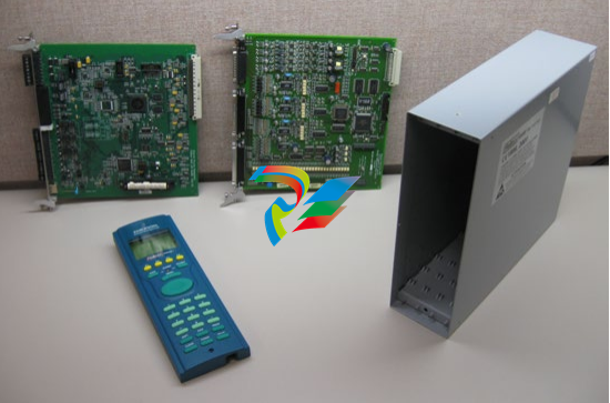
The S600+ uses a modular design that provides maximum flexibility
and ease of installation. The basic panel-mounted version consists of
three major components:
Fabricated metal case, complete with pre-installed PSU/backplane
and four card slots for the modules (a dedicated CPU slot and three
I/O slots).
Removable front panel comprising the LCD display and keypad
assembly.
Plug-in modules. A CPU module and one I/O module are supplied
for a basic configuration; two blank plates are supplied to cover the
unused slots.
Figure 2-1 shows the S600+ system components
Note: User-supplied tools to assist in the installation process may
include a Phillips screwdriver, a regular screwdriver, a small
adjustable spanner wrench, and a 2.5mm Allen key.
2.2 Environmental Considerations
The S600+ panel mounted flow computer is designed for use within
the control room. Place it in a position that provides ease of use,
comfort, and safety for operators and maintenance personnel. The
optimum height for viewing and using the display and keypad is at
operator eye level.
Caution If you install one or more units in a confined space with other heatproducing equipment, give special attention to the combined heating
effect. This combined heat could increase the environmental
temperature beyond its acceptable threshold, thereby impacting
performance.
2.3 Required Tools for Installation
Before you attempt to install the S600+, ensure that you have the
following tools:
Small flat-blade screwdriver suitable for the slot-headed captive
screws on the rear of the case that secure each plug-in board into
the case.
5.5 mm (5 BA) hex or small adjustable wrench for the front panel
bosses
2.5 mm Allen key suitable for the hex cap screw on the front face
of the front panel that secures the front panel molding to the case.
2.4 Installing the S600+
Refer to the following procedures for installing the various S600+
components, including the front panel, panel-mounted unit, and
modules.
2.4.1 Unpacking the S600+
Unpack the S600+ carefully and inspect parts for visual damage.
Note: Do not discard packaging material until after you have
identified all pieces of the shipment and you are confident that
all parts are working correctly.
2.4.2 Removing the Front Panel
To begin the mounting process, remove the front panel from the
S600+:
1. Ensure power has been removed from the S600+.
2. Using a 2.5 mm Allen key, remove the hex cap screw from the
bottom centre of the front panel (refer to Figure 2-2).
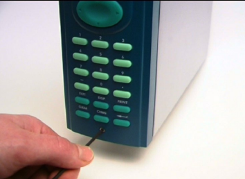
Note: A security cap may cover the hex cap screw.
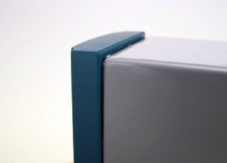
3. Carefully slide the front panel up 4 mm (0.15 in) to allow it to clear
the retaining groove at the top of the case, and then allow the panel
to come forward to clear the panel case completely (refer to Figure
2-3).
Figure 2-3. Lifted Front Panel
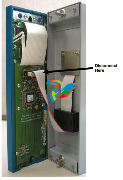
Disconnect the ribbon cable from the back of the front panel at the
blue connector (refer to Figure 2-4). Observe the orientation of the
connector with its mating keyway. You must correctly re-insert the
ribbon cable at the end of the installation process.
Caution Do not remove the ribbon cable from the S600+ housing. This might
damage the S600+. Also, the ribbon cable may also have an EMC
clamp. Be sure to leave it intact without damaging the ribbon cable.
5. Remove the top and bottom bosses from the unit housing, using a
5.5 mm (5 BA) hex wrench.
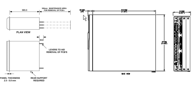
Table 2-1. Mounting Dimensions
Part Dimensions
Display Keypad Molding 85 mm (3.35") width x 269 mm (10.59") height x 28 mm (1.10") deep
Case 84.5 mm (3.327") width x 270 mm (10.63") height x 303.8 mm (11.94")
deep
Panel Cutout 66 mm (2.6") width x 150 mm (5.9") height
Pitch Between Cases 110 mm (4.33") giving 25 mm (0.98") air gap
Max Panel Thickness 10 mm (0.39")
Access Allow 300 mm (11.81") clearance directly behind case for maintenance
2.4.3 Installing the Panel-Mounted Unit
After removing the front panel, install the panel-mounted unit:
1. Keeping environmental considerations in mind, construct the
framework of the cubicle to support the operating panel.
Note: A standard 483 mm (19 in) rack that is 311 mm (12.25 in)
high can accommodate up to four S600+s provided you
support the rear of the case.
2. Refer to Figure 2-6 and Table 2-1 for position details for two 7 mm
(0.276 in) holes and a cutout. The panel cutout should be
-
 Beckhoff PLC module CX1020-0000 Basic CPU module (service phase)
 -
 Beckhoff CP7812-1056-0010 15" Multitouch Display Control Panel
 -
 Beckhoff CX5120-0115 /2GB Controller Module
 -
 Beckhoff CP7201-1000-0000 Industrial Panel PC
 -
 Beckhoff Servo Motor AM8061-0JH1-0000
 -
 BECKHOFF CP6503-0001-0050 Built-in Panel PC
 -
 Beckhoff CP3919-0010 Display G190ETN01.2 19" PCT V04. Multi-touch Control Panel
 -
 Beckhoff CX5110-0112-9020/000368201 Embedded PC Intel Atom Processor
 -
 Beckhoff AX8206-0000 Dual-Axis Module
 -
Beckhoff Nail Operating Terminal CP7032-1031-0010
-
Beckhoff AM8042-0EH1-0000 Servomotor 4.10 Nm (M0), F4 (87 mm)
-
 Beckhoff EK9300 Beckhoff CPU Module
 -
Beckhoff CP3224-0020 Multitouch-Panel-PC
-
 Beckhoff CP2712-0000 12.1" 24VDC Touch Screen WMD0
 -
 BECKHOFF CX5240-0195 / 0000289234 Embedded PC 40 GB CFast Card
 -
 Beckhoff CP6932-1000-0000 Control Panel
 -
 BECKHOFF CX5120-0121 PLC Module
 -
 Beckhoff EL3218 | EtherCAT Terminal, 8-channel analog input
 -
 Beckhoff C6640-0050 | Control cabinet Industrial PC
 -
 Beckhoff Cx5130-0120/4GB Embedded-PC
 -
 BECKHOFF CX2030-0122 PLC PROCESSOR
 -
 BECKHOFF CX5020-0122 Controller Module
 -
 Beckhoff CP3915-0000 Multitouch Panel
 -
 BECKHOFF EL3014 | EtherCAT Terminal
 -
 BECKHOFF Industrial Computer c6920-1057-0030
 -
 Beckhoff CX5130-0141/4GB CX5130-0141 Embedded PC
 -
 Beckhoff C6240-1052-0040 4-086-06-3073 Industrial Computer
 -
 Beckhoff CX5140-0135 /4GB High-Performance Embedded Industrial PC
 -
 Beckhoff C6515-1001-0000 Industrial PC
 -
 Beckhoff AX5103-0000-0200 - Digital Compact Servo Drives
 -
 Beckhoff CX2030-0130-1003/4GB Basic CPU module
 -
 Beckhoff AX8620-0000 Power Supply Module
 -
 Beckhoff CX9020-0111 module with
 -
 Beckhoff EL7332 PLC Module
 -
 BECKHOFF CP7709-0001-0020 HMI
 -
 Beckhoff CX5120-0155/2GB Embedded PC
 -
 BECKHOFF CP7037-1037-0010 OPERATOR INTERFACE TOUCHSCREEN
 -
 Beckhoff EK9000 | ModbusTCP/UDP Bus Coupler
 -
 Beckhoff Touch Panel Screen CP6020 -0000-0000
 -
 Beckhoff CX2020-0121 Module FAST Shipping
 -
 Beckhoff CX2030-0125 Basic CPU Module
 -
 Beckhoff CP3918-0000 Multi-Touch 18.5" Control Panel
 -
 Automotion LC4A00010 DC BL Motor Control, ATS, Sub Assy, SCP, 115VAC,
 -
 500T-115VAC - VAS ENGINEERING - DORIC 500 SERIES DIGITAL TEMP INDICATOR
 -
 Honeywell X-DCS2000/EN Digital Integrated System Manager 50/60Hz 100-240V #4
 -
 Kollmorgen S60600 Servostar600 606-Fan 4 kVA, 6 A, 3 X 230 - 480 V
 -
 ABB XZ C828 A101 Didt Dioder Snubber 3BHE039453R0101
 -
 ABB 3BHB027232R0001 1-Phase Charging Transformer
 -
 ABB 3BHE006412R0101 Circuit Board UFC762AE101
 -
 ABB XVC770BE101 3BHE021083R0101 Circuit Board
 -
 ABB 3BHE021887R0101 (Model: UBCC717BE101 / UBC717BE101) is an advanced
 -
 ABB 3BHE032593R0001 Isolated Power Supply
 -
 ABB 3BSC610023R0001 POWER SUPPLY SD812
 -
 Beckhoff C6650-0060 | Control cabinet Industrial PC
 -
 Beckhoff CP2916-0000 Industrial HMI Display Panel
 -
 Beckhoff AM8053-0L2B-0000 Servomotor 15.4 Nm (M0), F5 (104 mm)
 -
 Beckhoff CP6202-0001-0020 Industrial Panel PC
 -
Beckhoff CX2020-0120 Plc Module
-
 Beckhoff CX1010-0111 BASIC CPU MODULE
 -
 Beckhoff C6017-0010 | Ultra-compact Industrial PC
 -
 BECKHOFF CX2040-0155 Plc Module
 -
 Beckhoff CX5120-0125 Embedded PC
 -
 BECKHOFF C6930-0040 INDUSTRIAL CONTROL COMPUTER
 -
 Beckhoff CP6907-0001-0000 Economy Built-in Control Panel
 -
 Beckhoff CP2912-0000 Multi-Touch Built-In Control Panel
 -
 Beckhoff C6015-0010 Ultra-Compact Industrial PC
 -
 Beckhoff CX5130 | Embedded PC with Intel Atom® E3827
 -
 Beckhoff C6030-0060 Ultra-Compact Industrial PC
 -
 OMRON 3G3XV-A2007 3G3XV-A2007-NEV2
 -
 Omron NJ1019000 NJ1 programable logic controller
 -
 OMRON C120-LK202-EV1/C120LK202EV1
 -
 OMRON C200H-AD003 PLC
 -
 OMRON C200H-CPU23-E COIL 24VDC PLC
 -
 Omron C200HG - C200H-ID212- C200H-OC226 C200HW-BC101 PLC Base Unit
 -
 OMRON C200H-OC222(Output Unit),C200H-PS211(Power Supply Unit),SP001 Module Rack
 -
 OMRON C200H-RT201 PROGRAMMABLE CONTROLLER
 -
 OMRON C200HS-CPU01-E SYSMAC PROGRAMMABLE CONTROLLER
 -
 OMRON C200H-SNT31 C200H Programmable Controllers
 -
 OMRON C200HW-MC402-E Motion control unit
 -
 OMRON C200PC-ISA02-DRM-E PLC ISA bus compatible board card
 -
 OMRON C500-CT012 PLC
 -
 OMRON C500-NC103-E PLC
 -
 OMRON C500-NC222-E PLC
 -
 OMRON C500-PRW05-V1 PLC
 -
 OMRON C500-PRW06 PROGRAMMABLE CONTROLLER
 -
 OMRON C500-PS223-E 3G2A5-PS223-E PLC SYSMAC PROGRAMMABLE CONTROLLER
 -
 OMRON C500-TU001 3G2A5-TU001 PLC PLC
 -
 OMRON C60H-C1DR-DE-V1 Programmable Controllers
 -
 OMRON C60H-C5DR-DE-V1 Programmable Controllers
 -
 OMRON C60H-C6DR-DE-V1 Programmable Controllers
 -
 OMRON CJ1G-CPU44H CPU module
 -
 OMRON CJ1G-CPU45H PLC
 -
 OMRON CJ1M-CPU13-ETN V4.0 PLC PLC
 -
 OMRON CJ1W-AD041-V1 Analog input uni
 -
 OMRON CJ1W-CORT21 PLC module
 -
 OMRON CJ1W-IDP01 Input unit
 -
 OMRON CJ1W-MCH71 - MECHATROLINK-II
 -
 OMRON CJ1W-MD261 Digital I/O
 -
 OMRON CJ1W-NC413 Position control unit
 -
 OMRON CJ1W-NCF71 Position Control Units
 -
 OMRON CJ1W-PTS51 Process Simulation I/O Module
 -
 OMRON CJ1W-PTS52 Process Simulation I/O Module
 -
 OMRON CJ1W-SCU21-V1 PLC
 -
 Omron CJ1W-SCU22 Serial Communication Unit
 -
 OMRON CJ1W-TC001 CJ Series Temperature Control Unit
 -
 Omron CK3W-AX1515N Motion Controller
 -
 Omron CP1E-N60DR-D Compact PLC CPU
 -
 OMRON CP1E-NA20DT1-D PLC PLC
 -
 OMRON CP1H-X40DT-D plc PLC
 -
 OMRON CPM2C-S110C-DRT Interface module
 -
 OMRON CQM1-AD041 PLC
 -
 SAACKE F‑GDSA‑1 / F‑GDSA‑2 Feuerungsautomaten
 -
 SAACKE F-GDSA 143303 Controller SHIPS UPS
 -
 ICS Triplex T8270 Trusted 24 Vdc FanAssembly
 -
 SCHNEIDER M522220000 SA SM_DO16R 16 DIGITAL OUTPUTS MODULE
 -
 LENZ EPL10200-W EPZ-10203 CANPT010W3E
 -
 OMRON CQM1H-ADB21 PLC
 -
OMRON CQM1H-CPU61 PLC
-
 OMRON CQM1H-MAB42 PLC
 -
 OMRON CQM1-TC102 CQM1-TC101 PLC
 -
 OMRON CS1G-CPU44-EV1 PLC
 -
 OMRON CS1G-CPU44H CPU
 -
OMRON CS1H-CPU63-EV1 PLC
-
 OMRON CS1H-CPU66-V1 PLC
 -
 OMRON CS1W-CLK13 PLC communication module
 -
OMRON CS1W-EIP21 PLC
-
 OMRON CS1W-MAD44 PLC PLC
 -
 OMRON CS1W-SCU31-V1 CVM1-BC103 PLC


