
GE IS220PPRAH1A Emergency Turbine Protection Module
GE IS220PPRAH1A Emergency Turbine Protection ModuleTechnical Overview and Implementation GuideMay 16, 2025 | Industrial Automation | |
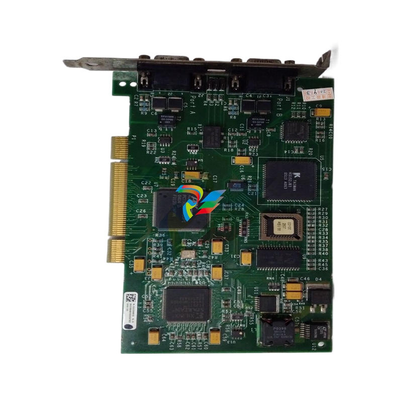 | Mark VIe Turbine Control System ComponentThe GE IS220PPRAH1A Emergency Turbine Protection Module is an essential component of the Mark VIe control system, designed to provide critical emergency protection for gas and steam turbine systems. This highly reliable module ensures turbine safety by monitoring and controlling key parameters in real-time, delivering fast response during emergency conditions. With its advanced architecture and robust design, the IS220PPRAH1A stands as a critical safeguard for high-value turbine assets in power generation and industrial applications, helping to prevent equipment damage and minimize operational downtime. |
IntroductionThe GE IS220PPRAH1A is an advanced Emergency Turbine Protection Module specifically engineered for the GE Speedtronic Mark VIe control system. As a critical safety component in turbine control applications, this module plays a pivotal role in ensuring the operational integrity and protection of gas and steam turbines in power generation facilities, oil and gas installations, and other industrial settings where turbine reliability is paramount. In today's power generation landscape, where turbine availability and equipment protection are directly linked to operational economics, the IS220PPRAH1A represents a sophisticated solution to turbine safety challenges. This technical article provides a comprehensive analysis of the module's architecture, functionality, integration considerations, and application scenarios to assist control system engineers and turbine operators in leveraging its capabilities effectively. | |
Technical Specifications | |
| Specification | Value |
|---|---|
| Part Number | IS220PPRAH1A |
| Series | Mark VI/VIe Turbine Control System |
| Manufacturer | General Electric |
| Product Type | Emergency Turbine Protection Module |
| Operating Temperature | -20°C to +55°C |
| Power Supply Voltage | Min: 27.4 VDC, Nominal: 28.0 VDC, Max: 28.6 VDC |
| Power Supply Current | Maximum 0.5 ADC |
| Compatible Terminal Board | IS200TREAH1A |
| Compatible Daughter Board | IS200WREAH1A |
| Speed Inputs | Six channels (configurable as three sets of speed pairs) |
| Speed Input Voltage Range | -15 VDC to +15 VDC |
| Contact Input Voltage | 0 to 32 VDC |
| E-stop Input Voltage | 18 to 140 VDC |
| Contact Outputs 1-2 | Up to 28 VDC, 7 ADC maximum |
| Contact Output 3 | Up to 28 VDC, 5 ADC maximum |
| Hazardous Location Rating | Approved for use in hazardous and non-hazardous locations |
System Architecture and ComponentsThe IS220PPRAH1A operates as part of a comprehensive turbine protection system, working in conjunction with specific terminal boards and daughter boards to create a complete protection solution. The module's architecture is designed with redundancy and reliability as core principles, ensuring that turbine protection remains intact even during component failures or abnormal operating conditions. Key System ComponentsThe complete turbine protection system using the IS220PPRAH1A typically includes:
This combination of components creates a comprehensive protection system that is approved for use in both hazardous and non-hazardous locations, making it suitable for a wide range of industrial environments. Architectural Features
| ||
Functional CapabilitiesThe IS220PPRAH1A provides a comprehensive set of protection functions specifically designed for turbine applications. These functions are implemented through a combination of firmware-based algorithms and hardware-enforced safety mechanisms, creating multiple layers of protection for the turbine system. Primary Protection FunctionsThe module implements several critical protection functions, including:
When any protection threshold is exceeded or abnormal condition detected, the PPRA module will trip the backup trip relays on the TREA terminal board and activate a trip signal to the primary control system, ensuring that the turbine is brought to a safe state rapidly and reliably. | ||
Speed Monitoring and ProtectionThe IS220PPRAH1A accepts six speed signals, configured as three sets of speed pairs, providing redundant speed measurement for reliable protection. This arrangement ensures that accurate speed information is available even if individual speed sensors fail. The module implements several speed-related protection functions:
This comprehensive approach to speed monitoring ensures that the turbine is protected against a wide range of potential issues, from simple overspeed conditions to more complex scenarios involving sensor failures or rapid changes in operating conditions. | ||
Integration and ConfigurationIntegrating the IS220PPRAH1A into a turbine control system requires careful planning and consideration of multiple factors. The following sections outline key aspects of the integration process. Hardware InstallationThe physical installation of the PPRA module involves several key steps:
Careful attention to wiring practices, grounding, and shielding is essential for ensuring reliable operation of the protection system, particularly for the speed sensor inputs which can be sensitive to electrical noise. | ||
Software ConfigurationConfiguration of the IS220PPRAH1A is performed through the GE ToolboxST software, which provides the interfaces necessary for defining protection parameters, alarm thresholds, and system behavior. The configuration process typically includes the following steps:
The configuration must be carefully validated to ensure that protection functions will operate correctly under all anticipated conditions, while avoiding nuisance trips that could impact plant availability unnecessarily. | ||
Application ScenariosThe IS220PPRAH1A is designed for use in a variety of turbine protection applications across different industries. The following sections highlight some of the key application scenarios where this module provides significant value. Gas Turbine ProtectionIn gas turbine applications, the IS220PPRAH1A provides critical protection against conditions that could lead to catastrophic failure, such as:
The module's independent operation from the primary control system ensures that protection remains available even if the main control system experiences failures, providing an essential safety net for high-value gas turbine assets. Steam Turbine ProtectionFor steam turbine applications, the IS220PPRAH1A addresses specific protection requirements, including:
| ||
Maintenance and TroubleshootingProper maintenance and troubleshooting procedures are essential for ensuring the continued reliable operation of the IS220PPRAH1A and associated protection systems. The following sections provide guidance on key maintenance and troubleshooting aspects. Preventive MaintenanceRegular preventive maintenance activities should include:
Comprehensive maintenance records should be maintained, documenting all inspections, tests, and any issues identified, along with corrective actions taken. Troubleshooting Common IssuesWhen issues arise with the protection system, systematic troubleshooting approaches can help identify and resolve problems efficiently. Common issues and troubleshooting steps include:
| ||
Best Practices for ImplementationImplementing the IS220PPRAH1A effectively requires attention to several best practices to ensure optimal protection system performance and reliability. System Design ConsiderationsWhen designing protection systems using the IS220PPRAH1A, consider the following best practices:
Testing and ValidationThorough testing and validation are essential for ensuring protection system reliability:
| ||
Series Comparison and Selection GuideGeneral Electric offers several variants of the emergency turbine protection module to address different application requirements. Understanding the differences between these variants is essential for selecting the most appropriate module for a specific application. | ||
| Model | Key Features | Typical Applications |
|---|---|---|
| IS220PPRAH1A | Original version with standard features for emergency turbine protection. Compatible with IS200TREAH1A terminal board and IS200WREAH1A daughter board. | Standard gas and steam turbine protection in power generation and industrial applications. |
| IS220PPRAS1A | Enhanced version with additional safety features. Compatible with IS200TREAS1A terminal board and IS200WREAS1A daughter board. | Applications requiring additional safety certification or enhanced protection features. |
| IS220PPRAS1B | Latest generation with updated hardware components and enhanced diagnostic capabilities. Compatible with IS200TREAS1A terminal board and IS200WREAS1A daughter board. | New installations and upgrades where the latest technology and enhanced diagnostics are desired. |
When selecting a protection module, consider factors such as:
Compatibility with existing control system components
Specific safety certification requirements
Need for advanced diagnostic capabilities
Long-term availability of spare parts and support
Integration with other protection and control systems
Consulting with GE application engineers can provide valuable guidance on selecting the most appropriate module for specific applications, particularly for complex installations or critical protection requirements.
ConclusionThe GE IS220PPRAH1A Emergency Turbine Protection Module represents a sophisticated solution for ensuring the safety and reliability of gas and steam turbines in power generation and industrial applications. With its comprehensive protection functions, robust design, and integration with the Mark VIe control system, it provides a critical safeguard for high-value turbine assets. By understanding the module's architecture, functionality, and implementation requirements, engineers and operators can effectively leverage its capabilities to build resilient protection systems that minimize the risk of turbine damage while maintaining high availability. As turbine control technology continues to evolve, the fundamental principles of independent, redundant, and diverse protection embodied in the IS220PPRAH1A remain essential for ensuring safe and reliable turbine operation. Whether implementing new turbine protection systems or upgrading existing installations, the technical considerations and best practices outlined in this article provide a foundation for successful deployment of the IS220PPRAH1A in a variety of industrial environments. |
-
 SAUTER Valve actuator ASM 105S/115S series ASM115SF152
 -
SAUTER Valve actuator ASM 105S/115S series ASM105SF152
-
SAUTER Valve actuator ASM 105S/115S series ASM115SF132
-
SAUTER Valve actuator ASM 105/115 series ASM105SF132
-
 SAUTER Valve actuator ASM 105/115 series ASM115F122
 -
SAUTER Valve actuator ASM 105/115 series ASM115F120
-
SAUTER Valve actuator ASM 105/115 series ASM105F122
-
SAUTER Valve actuator ASM 105/115 series ASM105F120
-
SAUTER Valve actuator ASM 105/115 series ASM105F10
-
 SAUTER AKF113S Rotating actuator AKF 112/113 series
 -
SAUTER AKF113F122 Rotating actuator AKF 112/113 series
-
SAUTER AKF113F120 Rotating actuator AKF 112/113 series
-
SAUTER AKF112F122 Rotating actuator AKF 112/113 series
-
SAUTER AKF112F120 Rotating actuator AKF 112/113 series
-
 SAUTER AKM115SAF332: Smart Actuator for ball valve, BACnet/IP
 -
 SAUTER AKM115SAF232 Rotating Actuator AKM 115SA Smart Actuator
 -
 SAUTER AKM115SF152 Rotating Actuator AKM 105S/115S Series
 -
SAUTER AKM115SF132 Rotating Actuator AKM 105S/115S Series
-
SAUTER AKM105SF132 Rotating Actuator AKM 105S/115S Series
-
 SAUTER AKM115F122 Rotating actuator AKM 105/115 series
 -
 SAUTER Rotating actuator AKM 105/115 series AKM115F120
 -
SAUTER Rotating actuator AKM 105/115 series AKM105F122
-
SAUTER Rotating actuator AKM 105/115 series AKM105F120
-
 SAUTER Continuous actuator for unit valves, with stroke AXS215S
 -
 SAUTER Linear valve actuator AXT/AXS series AXT211
 -
SAUTER Linear valve actuator AXT/AXS series AXT201
-
 SAUTER Linear valve actuator AXM/AXF series AXF217S
 -
SAUTER Linear valve actuator AXM/AXF series AXM217S
-
SAUTER AXM217SF404 is an electric actuator for unit valves.
-
SAUTER AXM217SF402 is an electric actuator for unit valves.
-
SAUTER Linear valve actuator AXM/AXF series AXM217
-
 SAUTER Linear valve actuator AVF 124/125 series AVF125S
 -
SAUTER Linear valve actuator AVF 124/125 series AVF124S
-
SAUTER Linear valve actuator AVF 124/125 series AVF124S
-
 SAUTER AVM322S-R Linear valve actuator AVM 234S series
 -
SAUTER AVM322-R Linear valve actuator AVM 234S series
-
SAUTER AVM322SF132 Linear valve actuator AVM 234S series
-
 SAUTER AVM321SF132 Linear Valve Actuator
 -
 GE Power Conversion P112-6053 Advanced Micro Controller (AMC2)
 -
GE Power Conversion P111-6053 Advanced Micro Controller (AMC2)
-
 GE Power Conversion P110-6053 Advanced Micro Controller (AMC2)
 -
 GE Power Conversion P122-6052 Advanced Micro Controller (AMC2)
 -
GE Power Conversion P121-6052 Advanced Micro Controller (AMC2)
-
 GE Power Conversion P112-6152 Advanced Micro Controller (AMC2)
 -
GE Power Conversion P110-6152 Advanced Micro Controller (AMC2)
-
GE Power Conversion P112-6052 Advanced Micro Controller (AMC2)
-
GE P106-6052 AMC2 Advanced Micro Controller Unit
-
SAUTER AVF234SF232 Linear valve actuator AVM 234S series
-
SAUTER AVF234SF132 Linear valve actuator AVM 234S series
-
 SAUTER Linear valve actuator AVM 234S series AVM234SF132-6
 -
SAUTER Linear valve actuator AVM 234S series AVM234SF132-5
-
SAUTER Linear valve actuator AVM 234S series AVM234SF132
-
SAUTER Linear valve actuator AVM215SF132-7
-
SAUTER Linear valve actuator AVM215SF132R
-
 Linear valve actuator AVM 115SA Smart Actuator AVM115SAF332
 -
Linear valve actuator AVM 115SA Smart Actuator AVM115SAF232
-
 SAUTER Linear valve actuator AVM 105S/115S series AVM115SF132
 -
SAUTER Linear valve actuator AVM 105S/115S series AVM105SF132
-
 SAUTER AVM115F901 Linear Valve Actuator
 -
SAUTER AVM115F122 Linear Valve Actuator
-
SAUTER AVM115F120 Linear Valve Actuator
-
SAUTER AVM105F122 Linear Valve Actuator
-
 SAUTER AVM105F120 Linear Valve Actuator
 -
 SAUTER AVM105F100 Linear Valve Actuator
 -
 AEROTECH SM Series High-Performance Stepper Motors
 -
 AEROTECH BLMSC Series Linear Motors
 -
 AEROTECH Custom Linear Motors
 -
 AEROTECH BMS Series Brushless, Slotless Rotary Motors
 -
 AEROTECH BM Series Brushless Rotary Motors
 -
 AEROTECH BLMX Series Linear Motors
 -
 AEROTECH BLMH Series Linear Motors
 -
 AEROTECH BLM Series Linear Motors
 -
 AEROTECH BLMC Series Linear Motors
 -
 AEROTECH BLMUC-143 Linear motor forcer with thermistor
 -
AEROTECH BLMUC-111 Linear motor forcer with thermistor
-
AEROTECH BLMUC-95 Linear motor forcer with thermistor
-
AEROTECH BLMUC-79 Linear motor forcer with thermistor
-
AEROTECH BLMUC Series Linear Motors
-
 AEROTECH Automation1 FLEX Distributed Amplifier Multi-Axis Servo Control System
 -
 AEROTECH Automation1 HXA4 6-Axis Hexapod Servo Drive
 -
 AEROTECH Automation1 iHXA4 6-Axis Hexapod Servo Drive with Motion Controller
 -
 AEROTECH Modular System Control Console
 -
 AEROTECH TV Series Transformers
 -
 AEROTECH TM Series Transformers
 -
 AEROTECH UFM Noise Filter Module
 -
 AEROTECH MFM Motor Filter Module
 -
 AEROTECH MPG Handwheel Pendant
 -
 AEROTECH Automation1 Multi-Axis Joystick
 -
 AEROTECH ETM Enhanced Throughput Module
 -
 AEROTECH Automation1 XL4s High-Speed, Single-Phase Linear Servo Drive
 -
 AEROTECH Automation1 XL2e Enhanced, Compact Linear Servo Drive
 -
 Automation1 iXL2e Enhanced, Compact Linear Servo Drive with Motion Controller
 -
 AEROTECH Automation1 XL5e Enhanced, Linear Servo Drive
 -
 AEROTECH Automation1 iXL5e Enhanced Linear Servo Drive with Motion Controller
 -
 AEROTECH Automation1 GI4 Laser Scan Head Controller
 -
 AEROTECH Automation1 SI4 Stepper Interface
 -
AEROTECH Automation1 XI4 Servo Interface
-
 AEROTECH AEROTECH Automation1 iXI4 Servo Interface with Motion Controller
 -
 AEROTECH Automation1 XC6e Enhanced, High-Power PWM Servo Drive
 -
 AEROTECH Automation1 iXC6e Enhanced, High-Power PWM Servo Drive with Motion Controller
 -
 AEROTECH Automation1 XC2 Compact PWM Servo Drive
 -
 AEROTECH Automation1 XC4 PWM Servo Drive
 -
 AEROTECH Automation1 GL4 Galvo Laser Scan Head Linear Drive
 -
 AEROTECH Automation1 XC2e Enhanced, Compact Servo Drive with PWM+
 -
 AEROTECH Automation1 XC4e Enhanced, PWM Servo Drive
 -
 AEROTECH Automation1 XR3 Multi-Axis Servo Drive Rack
 -
 AEROTECH Automation1 iXR3 Multi-Axis Servo Drive Rack with Motion Controller
 -
 AEROTECH Automation1 iXC2 Compact PWM Servo Drive with Motion Controller
 -
 AEROTECH Automation1 iXC2e Enhanced, Compact PWM+ Servo Drive with Motion Controller
 -
 AEROTECH Automation1 iXC4 PWM Servo Drive with Motion Controller
 -
 AEROTECH Automation1 iXC4e Enhanced, PWM Servo Drive with Motion Controller
 -
 AEROTECH Automation1 iPC Industrial PC with Motion Controller
 -
 AEROTECH EPICS & TANGO Drivers for Distributed Control Systems
 -
 AEROTECH .NET, C, Python & LabVIEW APIs Custom Application Develotpmen
 -
 AEROTECH Automation1 Industrial Ethernet Support
 -
 AEROTECH Automation1 iSMC Intelligent, Software-Based Motion Controller
 -
 AEROTECH Automation1 iXA4 1- 2- or 4-Axis PWM Servo Drive with Motion Controller
 -
 AEROTECH Automation1 XA4 1- 2- or 4-Axis PWM Servo Drive
 -
 CTI 2500-ADP2-DISC Discrete Wiring Adapter for Series 500
 -
 CTI 2500-ADP1 Analog Wiring Adapter for Series 500
 -
 CTI 2500C-RADP-RS485 Remote Base Controller Adapter for Series 500
 -
 CTI 2500C-RADP-RBC Profibus RBC Adapter for Series 500
 -
 CTI 2500C-PADP-120V 120VAC 50W Power Supply for Series 500
 -
 CTI 2500-RADP RBC Adapter for Series 500
 -
 CTI 2500-R4500 520/530/DBC Adapter for Series 500 - MATURE
 -
 CTI 2500-PADP Power Supply Adapter for Series 500
 -
 CTI 2500-IADP I/O Adapter for Series 500
 -
 CTI 2500-VP15A-N4-W7 15" Flat-Panel PC with Windows® 7 Embedded


