
schneiderInstruction MI 021-390 February 2016 I/A Series® Magnetic Flow Transmitter Model IMT25 Operation, Configuration, and Calibration
{012.000000}. Then press Shift + Change to enter Edit mode.
e. Use the Right/Left arrow keys to move the cursor under the digits you want to
change. Use the Up/Down arrow keys to change the digits to the desired values. In
the case of this example, continue this procedure until the display reads
[018.220000]. Use the Right arrow key to move the cursor out past the right
bracket to save the setting. The display then reads METER FACTOR?
{018.219998}. Note that in some cases, as with this example, a slightly different
value appears. The magnitude of this difference is insignificant.
NOTE
To determine the correct meter factor, refer to “Determining the Meter Factor” on
page 18.
f. Press the Right arrow key again. The display reads 3 CALIBRATION Meter
Factor.
5. Now that all changes have been made, press the Left arrow key until you are asked Go
On-Line? Reply Yes by pressing the Right arrow key. To display flow measurement,
press the Right arrow key once more.
! CAUTION
If you change the upper range value or engineering units in the Transducer Block with
the local display pushbuttons without making a corresponding change in the
corresponding Analog Input Blocks from a fieldbus host, a mismatch error occurs and
the Analog Input Block reverts to Out of Service mode.
Determining the Meter Factor
First find the “Cal Factor” or “IMT25 Cal Fact” on the flowtube data label.
If the flowtube data label has a “IMT25 Cal Fact.” listing, use that value as the “Meter Factor.”
If only a “Cal Factor” value is found on the flowtube data label, that value must be multiplied by
the appropriate factor from Table 2 to calculate the “Meter Factor.”
Operation from Keypad/Display Panel
For local operation, configuration, and calibration, all operator entries are made through a
5-button keypad and all data is presented on a 2-line x 16 character LCD display. The
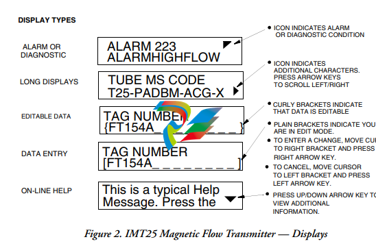
keypad/display of the IMT25 Transmitter is shown in Figure 1. Information on various types of
display is shown in Figure .
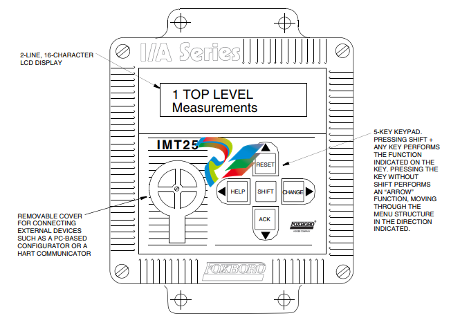
Figure 1. IMT25 Magnetic Flow Transmitter — Keypad/Display
All required functions are accomplished by using the four arrow keys alone and in combination
with the Shift key. Table 4 explains the function of each key
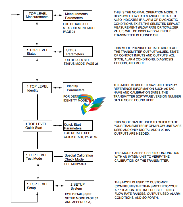
Top Level Menu
The Top Level menu displays the following modes – Measurements, Status, Identity, Quick Start
(in FoxCom and HART transmitters), Test Mode, and Setup. You can switch from one to another
in sequence by using the Up/Down arrow keys. To enter the second level menu from a particular
top level screen, press the Right arrow key. To return to the top level from a second level menu
item, press the Left arrow key. The level of the first, second, third, and fourth level menus is
indicated by the digit appearing as the first character in Line 1 of the display; a 1 indicates Level 1
(Top Level), a 2 indicates Level 2, and a 3 indicates Level 3, etc.
The top level menu is shown in Figure 3. For a complete presentation of all menu structures, refer
to Appendix A.
Measurements Mode
The Measurements mode, which is your main operating mode, is displayed upon startup.
Depending on the transmitter configuration, it has up to seven displays, any of which may be set
as the startup default. All screens can be scrolled with the Up/Down arrow keys.
Rate (EGU) — Shows current flow rate (forward or reverse) in the selected
engineering units.
Rate (% Range) — Shows current flow rate (forward or reverse) as a percentage of full
scale URV.
Fwd Tot — Shows current value of the forward totalized flow in engineering units.
Use the Net Tot display to reset.
Rev Tot — Shows current value of the reverse totalized flow in engineering units. Use
the Net Tot display to reset.
Net Tot — Shows current value of the net totalized flow (forward total - reverse total)
in selected engineering units. Press Shift + Reset to reset the displayed total to
zero. Resetting Net Tot also resets Fwd Tot and Rev Tot. It does not reset Gr Tot.
If Reset Totals is passcode protected, the message Enter Passcode appears.
Grand Tot — Shows current value of the grand total flow in engineering units. Press
Shift + Reset to reset the displayed total to zero. Resetting Gr Tot does not reset
Fwd Tot, Rev Tot, and Net Tot. If Reset Totals is passcode protected, the message
Enter Passcode appears.
If the Dual Display feature is configured On, a combination of two of these parameters can be
displayed at once. A typical dual display, in which Line 1 shows flow rate and Line 2 shows the
present forward total, is shown below. Units may not be displayed or may be truncated.
You may step through the displays of each of these parameters with the Up and Down arrow keys.
However, unless you specifically do so, the display defaults to that configured in Setup mode. The
engineering units and formats used in the displays are also configured in Setup mode.
Status Mode
The Status mode enables you to view fourteen system parameters and thus assess the performance
-
 BECKHOFF AX5106-0000-0200 | Digital Compact Servo Drives 1-channel
 -
 BECKHOFF C3620-0000 INDUSTRIAL COMPUTER (MOTORSHELVES)
 -
 Beckhoff EK1960-0000 TwinSAFE Compact Controller
 -
 Beckhoff C6930-0050 Control Cabinet Industrial PC
 -
 Beckhoff CP7711-0001-0030 Industrial Computer Detection
 -
 Beckhoff CX1001-0111 Embedded PC CPU Module
 -
 Beckhoff C6017-0020 | Ultra-compact Industrial PC
 -
 Beckhoff EK1322 | 2-port EtherCAT P junction with feed-in
 -
 Beckhoff CP2219-0010 Panel
 -
 BECKHOFF C6015-0020 ULTRA COMPACT INDUSTRIAL PC
 -
 BECKHOFF CX2030-0120/Standard CPU Module Embedded PC Windows PLC controller
 -
 Beckhoff CP7721-1090-0020 Panel PC
 -
 Beckhoff PC CPU Module CX5130-0175
 -
 Beckhoff C6920-0050 Control Cabinet
 -
 Beckhoff EL6631 EtherCAT 2-Port Communication Interface, Profinet RT Controller
 -
 Beckhoff CP6202-0001-0060 touch screen panel PC
 -
 Beckhoff CP3916-1002-0000 Multi-Touch Control Panel
 -
 Beckhoff EP1809-0021 | EtherCAT Box, 16-channel digital input, 24 V DC, 3 ms, M8Preferred type
 -
 Beckhoff CX8190 PLC Embedded Industrial PC Ethernet Controller
 -
 Beckhoff CX2100-0914 Power Supply for External
 -
 Beckhoff Automation CP6906-0001-0000 HMI
 -
 Beckhoff EP7342-0002 Module
 -
 Beckhoff CX1020-0112 / CX1100-0910 / CX1020-N010 / CX1100-0003 Windows CPU
 -
 Beckhoff EP7211-0034 EtherCAT Box 1 Channel Motion Interface
 -
 Beckhoff C6240-0030 Control cabinet Industrial PC
 -
 beckhoff motherboard CB1052-0004 CB1052-0004
 -
 Beckhoff AX2006-AS Servo Drive / Variable Frequency Drive
 -
BECKHOFF CP6207-0001-0020 NSMP
-
 Beckhoff C6930-1142-0060 Industrial Computer
 -
 Beckhoff FC7501-0000 interface card
 -
 Beckhoff CX5140-0175 Embedded PC PLC CPU CX5140 Industrial Controller
 -
 Beckhoff CP7802-1100-0010: High-End IP65 Control Panel with DVI/USB Extended Interface
 -
BECKHOFF CP3716-1058-0010 CONTROL PANEL
-
 Beckhoff AX8108-0000 Single-Axis Module
 -
 Beckhoff CU8851-0000 | USB extension, USB Extended 2.0 receiver box
 -
Beckhoff C6017-0030 | Ultra-compact Industrial PC
-
 Beckhoff CX1001-0120/CX10010120.cx1000-n001.cx1000-n000 System Overview
 -
 Beckhoff CPU Module CX5140-0155/4GB CPU Module
 -
 Beckhoff CP6533-0001-005: Built-in Panel PC with High-Definition Multi-Touch Control
 -
 Beckhoff EL5042 | EtherCAT Terminal, 2-channel encoder interface, BiSS® C
 -
 Beckhoff C6920-1080-0040: Premium Control Cabinet Industrial PC
 -
 Beckhoff C6920-0060 | Control cabinet Industrial PC
 -
 Beckhoff Embedded-PC CX5010-1121
 -
 Beckhoff CB3050-0010 Mainboard Motherboard
 -
 Beckhoff PLC module CX1020-0000 Basic CPU module (service phase)
 -
 Beckhoff CP7812-1056-0010 15" Multitouch Display Control Panel
 -
 Beckhoff CX5120-0115 /2GB Controller Module
 -
 Beckhoff CP7201-1000-0000 Industrial Panel PC
 -
 Beckhoff Servo Motor AM8061-0JH1-0000
 -
 BECKHOFF CP6503-0001-0050 Built-in Panel PC
 -
Beckhoff CP3919-0010 Display G190ETN01.2 19" PCT V04. Multi-touch Control Panel
-
 Beckhoff CX5110-0112-9020/000368201 Embedded PC Intel Atom Processor
 -
 Beckhoff AX8206-0000 Dual-Axis Module
 -
Beckhoff Nail Operating Terminal CP7032-1031-0010
-
Beckhoff AM8042-0EH1-0000 Servomotor 4.10 Nm (M0), F4 (87 mm)
-
 Beckhoff EK9300 Beckhoff CPU Module
 -
Beckhoff CP3224-0020 Multitouch-Panel-PC
-
 Beckhoff CP2712-0000 12.1" 24VDC Touch Screen WMD0
 -
 BECKHOFF CX5240-0195 / 0000289234 Embedded PC 40 GB CFast Card
 -
 Beckhoff CP6932-1000-0000 Control Panel
 -
 BECKHOFF CX5120-0121 PLC Module
 -
 Beckhoff EL3218 | EtherCAT Terminal, 8-channel analog input
 -
Beckhoff C6640-0050 | Control cabinet Industrial PC
-
 Beckhoff Cx5130-0120/4GB Embedded-PC
 -
 BECKHOFF CX2030-0122 PLC PROCESSOR
 -
 BECKHOFF CX5020-0122 Controller Module
 -
 Beckhoff CP3915-0000 Multitouch Panel
 -
 BECKHOFF EL3014 | EtherCAT Terminal
 -
 BECKHOFF Industrial Computer c6920-1057-0030
 -
 Beckhoff CX5130-0141/4GB CX5130-0141 Embedded PC
 -
 Beckhoff C6240-1052-0040 4-086-06-3073 Industrial Computer
 -
 Beckhoff CX5140-0135 /4GB High-Performance Embedded Industrial PC
 -
 Beckhoff C6515-1001-0000 Industrial PC
 -
 Beckhoff AX5103-0000-0200 - Digital Compact Servo Drives
 -
 Beckhoff CX2030-0130-1003/4GB Basic CPU module
 -
 Beckhoff AX8620-0000 Power Supply Module
 -
 Beckhoff CX9020-0111 module with
 -
 Beckhoff EL7332 PLC Module
 -
 BECKHOFF CP7709-0001-0020 HMI
 -
 Beckhoff CX5120-0155/2GB Embedded PC
 -
 BECKHOFF CP7037-1037-0010 OPERATOR INTERFACE TOUCHSCREEN
 -
 Beckhoff EK9000 | ModbusTCP/UDP Bus Coupler
 -
 Beckhoff Touch Panel Screen CP6020 -0000-0000
 -
 Beckhoff CX2020-0121 Module FAST Shipping
 -
 Beckhoff CX2030-0125 Basic CPU Module
 -
 Beckhoff CP3918-0000 Multi-Touch 18.5" Control Panel
 -
 Automotion LC4A00010 DC BL Motor Control, ATS, Sub Assy, SCP, 115VAC,
 -
 500T-115VAC - VAS ENGINEERING - DORIC 500 SERIES DIGITAL TEMP INDICATOR
 -
 Honeywell X-DCS2000/EN Digital Integrated System Manager 50/60Hz 100-240V #4
 -
 Kollmorgen S60600 Servostar600 606-Fan 4 kVA, 6 A, 3 X 230 - 480 V
 -
 ABB XZ C828 A101 Didt Dioder Snubber 3BHE039453R0101
 -
 ABB 3BHB027232R0001 1-Phase Charging Transformer
 -
 ABB 3BHE006412R0101 Circuit Board UFC762AE101
 -
 ABB XVC770BE101 3BHE021083R0101 Circuit Board
 -
 ABB 3BHE021887R0101 (Model: UBCC717BE101 / UBC717BE101) is an advanced
 -
 ABB 3BHE032593R0001 Isolated Power Supply
 -
 ABB 3BSC610023R0001 POWER SUPPLY SD812
 -
 Beckhoff C6650-0060 | Control cabinet Industrial PC
 -
 Beckhoff CP2916-0000 Industrial HMI Display Panel
 -
 Beckhoff AM8053-0L2B-0000 Servomotor 15.4 Nm (M0), F5 (104 mm)
 -
 Beckhoff CP6202-0001-0020 Industrial Panel PC
 -
Beckhoff CX2020-0120 Plc Module
-
 Beckhoff CX1010-0111 BASIC CPU MODULE
 -
 Beckhoff C6017-0010 | Ultra-compact Industrial PC
 -
 BECKHOFF CX2040-0155 Plc Module
 -
 Beckhoff CX5120-0125 Embedded PC
 -
 BECKHOFF C6930-0040 INDUSTRIAL CONTROL COMPUTER
 -
 Beckhoff CP6907-0001-0000 Economy Built-in Control Panel
 -
 Beckhoff CP2912-0000 Multi-Touch Built-In Control Panel
 -
 Beckhoff C6015-0010 Ultra-Compact Industrial PC
 -
 Beckhoff CX5130 | Embedded PC with Intel Atom® E3827
 -
 Beckhoff C6030-0060 Ultra-Compact Industrial PC
 -
 OMRON 3G3XV-A2007 3G3XV-A2007-NEV2
 -
 Omron NJ1019000 NJ1 programable logic controller
 -
 OMRON C120-LK202-EV1/C120LK202EV1
 -
 OMRON C200H-AD003 PLC
 -
 OMRON C200H-CPU23-E COIL 24VDC PLC
 -
 Omron C200HG - C200H-ID212- C200H-OC226 C200HW-BC101 PLC Base Unit
 -
 OMRON C200H-OC222(Output Unit),C200H-PS211(Power Supply Unit),SP001 Module Rack
 -
 OMRON C200H-RT201 PROGRAMMABLE CONTROLLER
 -
 OMRON C200HS-CPU01-E SYSMAC PROGRAMMABLE CONTROLLER
 -
 OMRON C200H-SNT31 C200H Programmable Controllers
 -
 OMRON C200HW-MC402-E Motion control unit
 -
 OMRON C200PC-ISA02-DRM-E PLC ISA bus compatible board card
 -
 OMRON C500-CT012 PLC
 -
 OMRON C500-NC103-E PLC
 -
 OMRON C500-NC222-E PLC
 -
 OMRON C500-PRW05-V1 PLC


