
GEMVME6100 Single-Board Computer Programmer’s Reference Guide
block diagram. The remainder of the chapter provides memory map
information including a default memory map, MOTLoad’s processor
memory map, a default PCI memory map, MOTLoad’s PCI memory map,
a PCI I/O memory map, and system I/O memory maps.
Note Programmable registers in the MV64360 system controller are
documented in a separate publication and obtainable from
Motorola Computer Group by contacting your Field Area
Engineer. Refer to Appendix A, Related Documentation, for
more information on obtaining this documentation.
Overview
The MVME6100 is a single-board computer based on the PowerPC
MPC7457 processor, the Marvell MV64360 system controller, up to 2 GB
of ECC-protected DDR DRAM, up to 128MB of Flash memory, a dual
Gigabit Ethernet interface, two asynchronous serial ports, and two
IEEE1386.1 PCI, PCI-X capable mezzanine card slots (PMCs
Memory Maps
Default Processor Memory Map
The MV64360 presents a default CPU memory map following RESET
negation. The following table shows the default memory map from the
point of view of the processor. Address bits [35:32] are only relevant for
the MPC7457 extended address mode and are not shown in the following
tables. (Note that it is the same as the GT-64260A with the addition of
integrated SRAM.)

ABORT_L
Abort. This bit reflects the current state of the onboard abort signal.
This is a debounced version of the abort switch and may be used to
determine the state of the abort switch. A set condition indicates that
the abort switch is not depressed while a cleared condition would
indicate that the abort switch is asserted.
FLASH_BSY_L
FLASH Busy. This bit provides the current state of the Flash Bank A
StrataFlash device Status pins. These two open drain output pins are
wire ORed. Refer to the appropriate Intel StrataFlash data sheet for a
description on the function of the Status pin.
FUSE_STAT
Fuse Status. This bit indicates the status of the onboard fuses. A
cleared condition indicates that one of the fuses is open. A set
condition indicates that all fuses are functional.
SROM_INIT
SROM Init. This bit indicates the status of the SROM Init. A cleared
condition indicates that the SROM Init is disabled. A set condition
indicates that the SROM Init is enabled and the MV64360 was
initialized using the MV64360 User Defined Initialization SROM at
$A6.
TSTAT_MASK
Thermostat Mask. This bit is used to mask the DS1621 temperature
sensor thermostat output. If this bit is cleared, the thermostat output
will be enabled to generate an interrupt on GPP3. If the bit is set, the
thermostat output is disabled from generating an interrupt.
FBOOTB_WP
Software Flash Bank B Boot Block Write Protect. This bit is to provide
software-controlled protection against inadvertent writes to the Flash
Bank B Top 1 MB (0xFFF00000) space. Clearing this bit and disabling
HW write-protect will enable writes to the Bank B Flash Top 1MB
boot block devices. This bit is set during reset and must be reset by the
system software to enable writing of the Flash Bank B boot block.
FBA_WP_HDR
Hardware Flash Bank A write protect header status. Read ONLY.
Hardware jumper configuration can not be overridden by the software
control bit 6 in this register.
FBOOTB_WP_HDR
Hardware Flash Bank B Boot Block write protect header status. Read
ONLY. Hardware jumper configuration can not be overridden by the
software control bit 3 in this register.
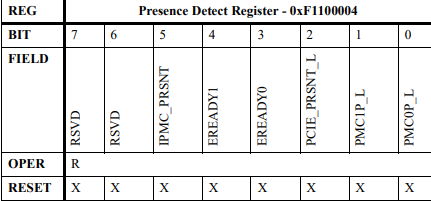
IPMC_PRSNT
IPMC Module Present. If set (HIGH true), there is PMCspan module
installed. If cleared, the PMCspan module is not installed.
EREADY1
EREADY1. Indicates that the PrPMC module installed in PMC slot 2
is ready for enumeration when set. If cleared, the PrPMC module is not
ready for enumeration. The PrPMC software must assert EREADY#
for this bit to be set. The purpose of EREADY# is to provide a
signaling method indicating that a non-monarch (vassal) PrPMC is
ready to be enumerated.
EREADY0
EREADY0. Indicates that the PrPMC module installed in PMC slot 1
is ready for enumeration when set. If cleared, the PrPMC module is not
ready for enumeration. The purpose of EREADY# is to provide a
signaling method indicating that a non-monarch (vassal) PrPMC is
ready to be enumerated.
-
 GE IS200AEPBH1B IS200AEPBH1B‑REV‑AA Pitch-Charger Control PCB Board
 -
 GE IS200EDEXG1ADA EX2100 SCR Trigger Control Board
 -
 GE 151X1207CK01SA01 IS200EDEXG1A EX2100 SCR
 -
 GE 151X1233DD02SA02 IS200AEPBH1B - Variant for pitch control charger assembly
 -
 GE 151X1233DB01SA01 IS200AEPBH1B - 10kW Wind Power Converter
 -
 GE 151X1233DB01SA01R | IS200AEPBH1B 10KW Converter
 -
GE 151X1233DD01SA02 Pitch Battery Charger (109W6931P001)
-
GE 151X1233DD01SA02 Pitch Battery Charger Assy IS200AEPBH1B
-
 GE 151X1233DB02SA02 Rev A IS200AEPBH1B Wind Turbine Converter
 -
 GE 151X1207CK02SA02 SCR 4400 V 1850 A IS200EDEXG1ADA General Electric EX2100
 -
 Triconex 3723X 32-Channel TMR Analog Input Module with HART
 -
 SHINKAWA VM-21G SIGNAL CONDITIONER SOCKET
 -
SHINKAWA VM-21R REVOLUTION SIGNAL CONDITIONER
-
SHINKAWA VM-21T DISPLACEMENT INPUT THRUST SIGNAL CONDITIONER
-
SHINKAWA VM-21D 6-WIRE LVDT SIGNAL CONDITIONER
-
 SHINKAWA VM-21P 3-WIRE LVDT SIGNAL CONDITIONER
 -
SHINKAWA VM-21A VIBRATION SIGNAL CONDITIONER
-
SHINKAWA VM-21K DISPLACEMENT INPUT VIBRATION SIGNAL CONDITIONER
-
 SHINKAWA VM-25S01 CONDITION MONITORING SYSTEM
 -
SHINKAWA VM-25 CONDITION MONITORING SYSTEM
-
SHINKAWA VM-772B DEVICE CONFIG
-
SHINKAWA VM-771B MCL VIEW
-
 SHINKAWA VM-76B INSTRUMENT RACK
 -
SHINKAWA VM-75B POWER SUPPLY MODULE
-
 SHINKAWA VM-742B NETWORK COMMUNICATION MODULE
 -
 SHINKAWA VM-741B LOCAL COMMUNICATION & PHASE MARKER MODULE
 -
SHINKAWA VM-722B 9-CHANNEL RELAY MODULE
-
SHINKAWA VM-707B AERODERIVATIVE GAS TURBINE MONITOR MODULE
-
 SHINKAWA VM-706B ROD DROP MONITOR MODULE
 -
 SHINKAWA VM-705B 18-CHANNEL TEMPERATURE MONITOR MODULE
 -
 SHINKAWA VM-704B TEMPERATURE MONITOR MODULE
 -
 SHINKAWA VM-702B ABSOLUTE VIBRATION MONITOR MODULE
 -
SHINKAWA VM-701B VIBRATION / DISPLACEMENT MONITOR MODULE
-
 SHINKAWA MODEL VM-5X INTERFACE UNIT
 -
 SHINKAWA MODEL VM-5W2 DUAL POWER SUPPLY INSTRUMENT RACK
 -
 SHINKAWA MODEL VM-5H4 INSTRUMENT RACK (for VM-5Z5.6.7)
 -
SHINKAWA MODEL VM-5G SINGLE UNIT INSTRUMENT RACK
-
SHINKAWA MODEL VM-5Z5,6,7 POWER SUPPLY UNIT
-
SHINKAWA MODEL VM-5Y1,2,3 RELAY MODULE UNIT
-
 SHINKAWA MODEL VM-5P3 PHASE MARKER UNIT
 -
 SHINKAWA MODEL VM-53 DUAL COMMUNICATION UNIT
 -
 SHINKAWA MODEL VM-52 BOTTOM HOLD MONITOR
 -
SHINKAWA MODEL VM-51 ROD DROP MONITOR
-
SHINKAWA MODEL VM-5R TACHOMETER
-
SHINKAWA MODEL VM-5S DUAL TACHOMETER
-
SHINKAWA MODEL VM-5A DUAL VALVE
-
SHINKAWA MODEL VM-5E DUAL CASE
-
SHINKAWA MODEL VM-5L COMPLEMENTARY INPUT
-
SHINKAWA MODEL VM-5N RAMP DIFFERENTIAL
-
SHINKAWA MODEL VM-5D DUAL DIFFERENTIAL
-
SHINKAWA MODEL VM-5T DUAL THRUST MONITOR
-
SHINKAWA MODEL VM-5C ECCENTRICITY MONITOR
-
SHINKAWA MODEL VM-5M DUAL PATH MONITOR
-
SHINKAWA MODEL VM-5B DUAL ACCELERATION MONITOR
-
SHINKAWA MODEL VM-5U DUAL SEISMIC MONITOR
-
SHINKAWA MODEL VM-55 VIBRATION MONITOR
-
 SHINKAWA VM-742B1-5 VIBRATION MONITORING SYSTEM CARD
 -
 Shinkawa PSP-17B P-24-64A P-24-64B Circuit Board Module
 -
 SHINKAWA MGP-67 PCB
 -
 Shinkawa JBP-278 P-22-48A-1 P-22-48B-1 Circuit Board Module
 -
 Shinkawa VM-721B 18-CHANNEL RELAY MODULE
 -
Shinkawa FRP-337 P-26-54A P-26-54B Circuit Board Module
-
 Shinkawa CPP-111 P-25-59A P-25-59B Circuit Board Module
 -
Shinkawa WKN-142K2-2 Vibration Transmitter
-
 SHINKAWA VL-202A08L-1012 Rotor Position Monitor Probe Sensor
 -
 Shinkawa CPP-128 P-26-74A P-26-74B Circuit Board Module
 -
 Honeywell 51402755-100 PROCESSOR CARD
 -
 Honeywell 51107595-100 Power
 -
HONEYWELL 51304544-100 Control Board
-
 HONEYWELL 51109919-100 BOARD
 -
 HHoneywell 51204160-175 Digital Input Module
 -
 Honeywell 51304754-150 High Level Analog Input Module
 -
 HONEYWELL 51304690-100 DIGITAL INPUT CARD
 -
 Honeywell 51401635-150 COMM CONTROL
 -
 HONEYWELL 51204174-175 MC-TAOY 52 ANALOG OUTPUT BOARD
 -
 HONEYWELL 51400596-100
 -
 HONEYWELL 51401291-100 board card
 -
 HONEYWELL 51401642-150 I/O LINK MODULE
 -
 Honeywell LCN‑E Hub Power Supply 38500148‑300
 -
 Honeywell LCN‑E Hub redundant 38500143‑202 Twisted‑pair LCN
 -
 Honeywell LCN‑E Hub non‑redundant,38500143‑102
 -
Honeywell Enhanced Micro‑TDC‑3000 System Unit MX‑DTAC01K2
-
 Honeywell Enhanced Micro‑TDC‑3000 System Unit MX‑DTAB01K2
 -
 Honeywell Enhanced Micro‑TDC‑3000 System Unit MT11‑520
 -
 Honeywell STI‑CE Smart Transmitter Interface 51304516‑150
 -
 Honeywell STI Smart Transmitter Interface 51304516‑100 MC‑PSTX02
 -
 Honeywell ulse Counter IOP,51304386‑100.MU‑PPIX02
 -
 Honeywell DO Digital Output IOP‑CE 51304487‑150 CE version
 -
.png) Honeywell DO Digital Output IOP 51304487‑100 MC‑PDOX02
Honeywell DO Digital Output IOP 51304487‑100 MC‑PDOX02 -
 Honeywell TDC‑3000 SOE DI IOP,51402625-175 MC‑PDIS12
 -
 Honeywell TDC‑3000 DI Digital Input IOP‑CE 51304485‑150
 -
Honeywell TDC‑3000 DI Digital Input IOP 51304485‑100 MC‑PDIX02
-
Honeywell TDC‑3000 AO Analog Output IOP 51304757‑100 MU‑PAOX02
-
Honeywell TDC‑3000 TC Thermocouple IOP 51304756‑100 MU‑TAMT03
-
 Honeywell TDC‑3000 51304755‑100 MU‑TAMR03
 -
 Honeywell TDC‑3000 LLAI Multiplex AI IOP,51304362‑150
 -
 Honeywell TDC‑3000 HLAI Analog Input IOP‑CE,51304363‑150
 -
 Honeywell TDC‑3000 HLAI Analog Input IOP,51304363‑100.4‑20mA
 -
Honeywell TDC‑3000 HPM Power Supply,51401731‑100
-
 Honeywell TDC‑3000 Standard 1986.HPM High‑Performance PM CPU,51402362‑100
 -
Honeywell TDC‑3000 APM Advanced Process Manager CPU,51304459‑100
-
Honeywell TDC‑3000 Standard 1986.PM Process Manager CPU,51304362‑100
-
Honeywell TDC‑3000 NIM Network Interface Module,51304481‑200
-
 Honeywell TDC‑3000 NIM Network Interface Module 51304481‑100
 -
 Honeywell TDC‑3000 BASIC,LCN Terminator Resistor,30732052‑001.Coaxial
 -
Honeywell TDC‑3000 BASIC,Hiway Coupler,30753732-001
-
 Honeywell TDC‑3000 BASIC,LEPIU Low‑Energy PIU,4DP7APCFA309
 -
Honeywell TDC‑3000 BASIC,HLPIU High‑Level PIU,4DP7APCFA106
-
Honeywell TDC‑3000 BASIC,Multifunction Controller(TDC‑2000 DHW),4DP7MFA103
-
 Honeywell TDC‑3000 BASIC,Extended Controller(TDC‑2000 DHW),4DP7AXA102
 -
Honeywell TDC‑3000 BASIC,Basic Controller(TDC‑2000 DHW),4DP7BBA101
-
Honeywell TDC‑3000 BASIC,XLCNE2 LCN Extender,51305508‑100.Coaxial LCN
-
 Honeywell TDC‑3000 BASIC,E‑PLCG PLC Gateway,51400997‑200
 -
 Honeywell TDC‑3000 BASIC,PLNM Plant Network Module,51401163‑100
 -
 Honeywell TDC‑3000 BASIC,CG Computer Gateway,80360206‑001
 -
 Honeywell TDC‑3000 BASIC,HG High‑Speed Gateway,51304526‑100
 -
 Honeywell TDC‑3000 BASIC,HM History Module,51191596‑200
 -
Honeywell TDC‑3000 BASIC,HM History Module,51191596‑100
-
Honeywell TDC‑3000 BASIC,AM Application Module CPU,51401551‑800.K2LCN‑8
-
Honeywell TDC‑3000 BASIC,AM Application Module CPU,51401551‑600.K2LCN‑6
-
 Honeywell TDC‑3000 BASIC,AM Application Module CPU,51401551‑400,K2LCN‑4
 -
 Honeywell TDC‑3000 BASIC,AM Application Module CPU,51401551‑300.K2LCN‑3
 -
Honeywell TDC‑3000 BASIC,AM Application Module CPU,51401551‑200,K2LCN‑2
-
 Honeywell TDC‑3000 BASIC,US Universal Station CPU,51401288‑200
 -
TDC‑3000 BASIC,US Universal Station CPU,51401288‑100
-
 SHINKAWA VM-21P1 Signal Conditioner 0-50MM 24VDC
 -
 Shinkawa RiverNew Vibration Transducer VK202 Series
 -
 Shinkawa Electric VM-3E2 Vibration Monitor Module


