
parkerQUICK START MANUAL VM600 machinery protection system (MPS)
is available at the rear of the rack, on the rear panel associated with the RPS6U power supply
or supplies.
NOTE: Refer to the VM600 system rack (ABE040 and ABE042) data sheet for further
information on the power supply check relay.
As shown in Figure 1-12, the connector for the power supply check relay has three pins that
provide access to the relay contacts, defined from left to right as COM, NO and NC.
Apart from the power supply check relay connector, the other components shown in
Figure 1-12 are mounted on the VM600 rack (ABE04x) backplane.
THE POWER SUPPLY CHECK RELAY IS SPECIFIED FOR OPERATION WITH SEPARATED
OR SAFETY EXTRA-LOW VOLTAGE (SELV) SYSTEM VOLTAGE LEVELS:
• MAXIMUM SWITCHING VOLTAGE OF ±30 VRMS / ±42.4 VAC(PEAK) OR 60 VDC
Handling cards
1.5.1 Card locations
The VM600 MPS rack (ABE04x) is a modular system with 21 card (VME) slots, designated
slot 0 to slot 20 (from left to right, as seen from the front). See Figure 1-4.
The front and rear card cages of the rack are partitioned by a backplane. Each side of the
back plane is equipped with connectors allowing modules and cards to be quickly and easily
installed.
The following elements are connected to the backplane by installing them from the front of
the rack:
• AMC8 analog monitoring card
• CPUM modular CPU card
• MPC4 machinery protection card
• RPS6U mains power supply unit
The following elements are connected to the backplane by installing them from the rear of the
rack:
• IOC4T input/output card, for use with the corresponding MPC4
• IOC8T input/output card, for use with the corresponding AMC8
• IOCN input/output card, for use with the corresponding CPUM
• IRC4 intelligent relay card
• RLC16 relay card.
If the ABE04x rack is intended for use as a condition monitoring system (CMS) as well as an
machinery protection system (MPS), it can contain additional hardware:
• XMx16/XIO16T extended monitoring card pairs.
NOTE: Further information on the condition monitoring system hardware can be found in
the VM600 condition monitoring system (CMS) hardware manual.
Operating personnel should remember to observe the handling
precautions mentioned in Handling precautions for electrostatic sensitive
devices on page x when handling cards.
Failure to do this may result in cards becoming damaged by electrostatic
discharges.
Before inserting a card in a rack, visually check that none of the connector
pins are ben
Communicating with a VM600 MPS
The VM600 MPS may be configured in several ways, depending on the hardware installed in
the VM600 rack (ABE04x). Figure 1-13 shows the various possibilities for communicating
with the system. In all cases, one of the VM600 MPSx software packages (MPS1 or MPS2)
is required to perform the configuration.
Figure 1-13 (a) shows the simplest VM600 MPS configuration. This is a stand-alone rack, that
is, one not containing a CPUM card. In this case, each MPC4 or AMC8 card in the rack must
be programmed individually from a personal computer over an RS-232 link
(see 1.7 Connecting to a computer).
Figure 1-13 (b) shows a rack containing a CPUM modular CPU card. An Ethernet link may
be established between the personal computer and the VM600 MPS via this card. The
connection is made on the front panel of the CPUM, hence at the front of the rack.
Communication between the CPUM and the MPC4 / IOC4T or AMC8 / IOC8T card pair takes
place over a VME bus on the rack backplane.
Figure 1-13 (c) shows a rack containing a CPUM modular CPU card and the corresponding
IOCN input/output card. A connection may be established between the personal computer
and the VM600 MPS via the IOCN. The connection is made on the IOCN panel, hence at the
rear of the rack. Communication between the CPUM / IOCN card pair and the MPC4 / IOC4T
or AMC8 / IOC8T card pair takes place over a VME bus on the rack backplane.
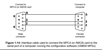
Connecting to a computer
The MPC4 and AMC8 cards have 9-pin D-sub RS-232 connectors. This can be used to
configure cards in a stand-alone rack. This is achieved using an interface cable from a
personal computer running one of the VM600 MPSx software packages (MPS1 or MPS2).
Details of the interface cable connections are shown in Figure 1-14.
8 Software configuration
The configuration of individual channels on the MPC4 and AMC8 cards must be made using
software before the system can be used. One of the VM600 MPSx software packages (MPS1
or MPS2) should be used to do this once the rack is powered up. For a stand-alone rack, the
configuration can be downloaded from a computer to each MPC4 and/or AMC8 card in turn
via an RS-232 link (see 1.7 Connecting to a computer). Alternatively, if the rack contains a
CPUM card (and, optionally, its corresponding IOCN card), the configuration can be
downloaded over an Ethernet link.
The majority of parameters are normally configured in the factory before delivery. The user
is nevertheless able to modify certain parameters if required using one of the VM600 MPSx
software packages (MPS1 or MPS2).
NOTE: Refer to the VM600 MPS1 configuration software for machinery protection systems
software manual or VM600 MPS2 configuration software for machinery protection
systems software manual for further information.
1.8.1 Setting the IP address of the CPUM card
-
 Applied Materials (AMAT) 0190-04098 | 5.X Factory Interface I/O Distribution Board
 -
 Applied Materials (AMAT) 0190-03705 | MF Producer SE/E Interlock Module
 -
 Applied Materials (AMAT) 0190-02748 | Flex Scanner Transition Module
 -
 Applied Materials (AMAT) 0190-02362 | Mainframe Interlock 1 Relay Module
 -
 Applied Materials (AMAT) 0190-01227 | Intelligent Motor Control OMS Board
 -
 Applied Materials (AMAT) 0190-00318 | VME 486 Video Controller
 -
 Applied Materials (AMAT) 0130-14007 | Advanced RF Signal Assembly
 -
 Applied Materials (AMAT) 0130-14005 | RF Cable/Interface Assembly
 -
 Applied Materials (AMAT) 0130-01218 | High-Efficiency RF Interface Controller
 -
 Applied Materials (AMAT) 0110-77040 | Head Pneumatic Controller
 -
 Applied Materials (AMAT) 0110-00077 | Precision Control Module
 -
 AMAT 0101-57015 high-performance Next-Generation Deflection Amplifier Board
 -
 AMAT 0100-77040 critical Head Pneumatic Controller Board
 -
 AMAT 0100-76291 Data Buffer / Memory Expansion Interface
 -
 AMAT 0100-76290 Advanced I/O Interface Board
 -
 AMAT 0100-76269 Control Board / Interface Module
 -
 AMAT 0100-71462-01 high-performance Process Controller PCB
 -
 AMAT 0100-71171 Chamber Interlock Control PCB
 -
 AMAT 0100-71154 Semiconductor Circuit Board / Electronic Group Card
 -
 AMAT 0100-70034 PCB Assembly (PCBA) for Endpoint VGA I/O Interconnect.
 -
 AMAT 0100-38032 ESC (Electrostatic Chuck) Controller PCB
 -
 AMAT 0100-36035 DPS Source Match / Seriplex I/O Distribution PCB
 -
 AMAT 0100-35231 Seriplex I/O Distribution Module
 -
 AMAT 0100-35217 TC Amp Interlock PCB Module
 -
 AMAT 0100-35065 High-Precision Serial Isolator PCB
 -
 AMAT 0100-35054 Advanced Chamber Interface Module
 -
 AMAT 0100-20453 DeviceNet Digital I/O Interface Board
 -
 AMAT 0100-20100 High-Performance Semiconductor Component
 -
 AMAT 0100-20068 Precision CCD Image Control Board
 -
 AMAT 0100-20064 Advanced Semiconductor Control Module
 -
Applied Materials (AMAT) 0100-20018 Advanced Communication Interface Module
-
 Applied Materials (AMAT) 0100-20016 High-Performance Interface and Control Module
 -
 Applied Materials (AMAT) 0100-20003 Digital I/O (DI/DO) Interface Board
 -
 Applied Materials (AMAT) 0100-20001 System Electronics Interface (SEI) / PCB Assembly
 -
 Applied Materials (AMAT) 0100-11030 Chamber Hardware / Gas Distribution Component
 -
 Applied Materials (AMAT) 0100-11022 Semiconductor Board Card
 -
 Applied Materials (AMAT) 0100-11018 Advanced Interface Control Module
 -
 Applied Materials (AMAT) 0100-11001 Precision Analog Output Board
 -
 Applied Materials (AMAT) 0100-11000 High-Precision Analog Input Board
 -
 Applied Materials (AMAT) 0100-09237 Advanced Signal Interface Module
 -
 Applied Materials (AMAT) 0100-09204 Advanced Digital Interface Control Board
 -
 Applied Materials (AMAT) 0100-09172 High-Density Digital I/O Control Board
 -
 Applied Materials (AMAT) 0100-09137 High-Performance VME Control Module
 -
 Applied Materials (AMAT) 0100-09054 Precision Analog Input Board
 -
 Applied Materials (AMAT) 0100-09029 Turbo Interconnect Interface Module
 -
 AMAT 0100-03391 Precision Semiconductor Control
 -
 AMAT 0100-01984 | VME System Interface & Logic Controller Board
 -
 AMAT 0100-01363 | VME Intelligent System Control & I/O Board
 -
 AMAT 0100-01321 | VME DeviceNet Scanner / Interface Board
 -
AMAT 0100-00793 | VME Multi-Channel Interface & Logic Board
-
 AMAT 0100-00689 | VME PCB Power Module
 -
 AMAT 0100-00580 | VME Intelligent System Controller Board
 -
 AMAT 0100-00523 | VME Multi-Channel Analog-to-Digital (A/D) Board
 -
 AMAT 0100-00493 | VME Multi-Function System Controller Board
 -
 AMAT 0100-00398 | VME Interface System Control Board
 -
 AMAT 0100-00369 | VME 12-Channel High-Speed Stepper Motor Controller
 -
 AMAT 0100-00196 | VME System Mainframe CPU Controller Board
 -
 AMAT 0100-00169 | VME 12-Channel Stepper Motor Controller Board
 -
 AMAT 0100-00162 | VME Dual Channel Serial Communication Board
 -
 AMAT 0100-00137 | VME Stepper Motor Controller Interface Board
 -
 AMAT 0100-00075 | VME Digital Input/Output (DI/O) Interface Board
 -
 AMAT 0100-00007 VME Analog Input/Output Interface Board
 -
 AMAT 0100-00002 | VME Slave I/O Interface PCB
 -
 AMAT 0090-05596 High-Voltage DC Power Cable Assembly
 -
 AMAT 0090-01809 | High-Performance RF Power Cable Assembly
 -
 AMAT 0010-29958 | CCM HART 3 Mainframe Control Assembly
 -
 AMAT 0010-20003 System Controller Card Cage Assembly
 -
.png) AMAT 0010-11239 PVD High-Voltage Power Interface Assembly
AMAT 0010-11239 PVD High-Voltage Power Interface Assembly -
 AMAT 0010-09416 RF Matching Network Assembly
 -
 AMAT 0010-00019 Analog Power Supply Assembly
 -
 AMAT AS00009-02 (31-000-00940) | Precision Semiconductor Component
 -
 AMAT 0010-00028 Power Supply Module
 -
 AMAT 0330-1586A Serial Communication PCB
 -
 AMAT 0190-09690 Seriplex SENSORbus SPX-MUXADIO-001
 -
 AMAT 0190-04397 DeviceNet I/O Interface Board
 -
 AMAT 0190-02506 DeviceNet I/O Interface Card
 -
 AMAT 0090-00475 Seriplex 210 MUXADIO
 -
 AMAT 410-0198-1 Multi-Output Switching Power Supply
 -
 AMAT 0100-20458 high-reliability Configurable Interlock Personality Board
 -
 AMAT VAS104350-0415 Gasline Heater Control Unit
 -
 AMAT VME6U1V2 VMEbus Backplane Interface Module
 -
AMAT 0920-01070 high-performance RF Power Generator
-
 AMAT 0090-76133A VME Single Board Computer (SBC)
 -
 AMAT 0190-24115 DeviceNet I/O Interface Card
 -
 AMAT 0190-37607 Backplane / Base Board Assembly
 -
 AMAT 0190-32372 Analog Input/Output (I/O) Board
 -
 AMAT 0190-09956 Loadlock Interface PCB Base Assembly
 -
 AMAT 0190-07908 four-channel DeviceNet Interface Card
 -
 AMAT 0190-07905 (UPS) control board
 -
 AMAT 0190-07502 Precision Controller / Interface Board
 -
 AMAT 0190-03680 I/O Backplane
 -
 AMAT 0190-02200 Water Leak Detection Control Board
 -
 AMAT 0100-76124 Digital I/O Board Assembly
 -
 AMAT 0100-35563 Leak Detector Configuration PCB
 -
 AMAT 0100-35250 Chamber Interface DPS Centura PCB
 -
 AMAT 0100-35124 Seriplex I/O Distribution Board
 -
 AMAT 0100-35058 Loadlock Interlocks PCB
 -
 AMAT 0100-20213 RF Match Detector PCB
 -
 AMAT 0100-20063 Interface PCB Assembly
 -
 AMAT 0100-09225 TC AMP/INTERLOCK PCB
 -
 AMAT 0100-09153 Gas Panel Interface PCB
 -
 AMAT 0100-09127 Loader Interconnect Board
 -
 AMAT 0100-09009 Buffer I/O PCB Card
 -
 AMAT 0100-02813 Signal Conditioning Board
 -
 AMAT 0100-01911 AC Gas Heater Control Board
 -
 AMAT 0100-01708 Pedestal Integration PCB
 -
 AMAT 0100-00658 300mm RTP Controller Distribution PCB
 -
 AMAT 0100-00582 Gas Panel Controller Backplane
 -
 AMAT 0100-00049 Analog Signal Conditioner
 -
 AMAT 0100-00008 Control Interface Module
 -
 AMAT 0090-03402 DC Power Supply / Power Module
 -
 AMAT 0090-01248 DC Power Supply / Power Module
 -
 AMAT 0090-76109 RF Matching / Capacitor Assembly
 -
 AMAT 0101-57106 Substrate Voltage Board
 -
 AMAT 0101-57014 Deflection-Amplifier PCB
 -
 AMAT 0101-57012 AKT Column Control PCB (COL-C 50-10)
 -
 AMAT AKT 0241-58482 PCB
 -
 AMAT 0241-58255 REV05 PCB
 -
 AMAT 0161-57042 AKT framework
 -
 AMAT 0101-57196 electronic control board
 -
 AMAT 0101-57178 Digital Input / Interface PCB
 -
 AMAT 0101-57162 electronic control board
 -
 AMAT 0101-57127 P-DRV (Power Driver Board)
 -
 AMAT 0101-57126 D-AMP 50-06 (Digital/Analog Amplifier)
 -
 AMAT 0101-57125 AKT COL-C Communication Board
 -
AMAT 0101-57120 D-OUT 50-32 (Digital Output Board)
-
 AMAT 0101-57112 D-IN 50-32 (Digital Input Board)
 -
 AMAT 0101-57102 electronic control board


