
GE VMIVME-5576 Fiber-Optic Reflective Memory with Interrupts
VMIVME-5576
Fiber-Optic Reflective Memory with Interrupts
High-speed, easy-to-use fiber-optic network (170 Mbaud serially)
Data written to memory in one node is also written to memory in all nodes on
the network

Up to 2.000 m between nodes and up to 256 nodes
Data transferred at 6.2 Mbyte/s without redundant transfer
Data transferred at 3.2 Mbyte/s with redundant transfer
Any node on the network can generate an interrupt in any other node on the
network or in all network nodes with a single command
Error detection
Redundant transmission mode for suppressing errors
No processor overhead
No processor involvement in the operation of the network
Up to 1 Mbyte of Reflective Memory
A24:A32:D32:D16:D8 memory access
Single 6U VMEbus board
INTRODUCTION
VMIVME-5576 is a
high-performance, multidrop VME-to-VME network. Data is
transferred by writing to on-board global RAM. The data is
automatically sent to the location in memory on all Reflective
Memory boards on the network.
PRODUCT OVERVIEW
—
The Reflective Memory
concept provides a very fast and efficient way of sharing data
across distributed computer systems.
VMIC’s VMIVME-5576 Reflective Memory interface
allows data to be shared between up to 256 independent
systems (nodes) at rates up to 6.2 Mbyte/s. Each Reflective
Memory board may be configured with 256 Kbyte to 1 Mbyte
of on-board SRAM. The local SRAM provides fast Read
access times to stored data. Writes are stored in local SRAM
and broadcast over a high-speed fiber-optic data path to other
Reflective Memory nodes. The transfer of data between nodes
is software transparent, so no I/O overhead is required.
Transmit and Receive FIFOs buffer data during peak data
rates to optimize CPU and bus performance to maintain high
data throughput.
The Reflective Memory also allows interrupts to one or
more nodes by writing to a byte register. These interrupt (three
level, user definable) signals may be used to synchronize a
system process, or used to follow any data that may have
preceded it. The interrupt always follows the data to ensure the
reception of the data before the interrupt is acknowledged.
The VMIVME-5576 requires no initialization unless
interrupts are being used. If interrupts are used, vectors and
interrupt levels must be written to on-board registers and the
interrupts armed.
Each node on the system has a unique identification
number between 0 and 255. The node number is established
during hardware system integration by placement of jumpers
on the board. This node number can be read by software by
accessing an on-board register. In some applications, this node
number would be useful in establishing the function of the
node.
LINK ARBITRATION — The VMIVME-5576 system
is a fiber-optic daisy chain ring as shown in Figure 2. Each
transfer is passed from node to node until it has gone all the
way around the ring and reaches the originating node. Each
node retransmits all transfers that it receives except those that
it had originated. Nodes are allowed to insert transfers
between transfers passing through.
INTERRUPT TRANSFERS — In addition to
transferring data between nodes, the VMIVME-5576 will
allow any processor in any node to generate an interrupt on
any other node. These interrupts would generally be used to
indicate to the receiving node that new data has been sent and
is ready for processing. These interrupts are also used to
indicate that processing of old data is completed and the
receiving node is ready for new data.
Three interrupts are available. The user may define the
function, priority, and vector for each interrupt. Any
processor can generate an interrupt on any other node on the
network. In addition, any processor on the network can
generate an interrupt on all nodes on the network. Interrupts
are generated by simply writing to a single VMIVME-5576
register.
All data and interrupt command transfers contain the
node number of the node that originated the transfer. This
information is used primarily so the originating node can
remove the transfer from the network after the transfer has
traversed the ring. The node identification is also used by
nodes receiving interrupt commands. When a node receives
an interrupt command for itself, it places the identification
number of the originating node in a FIFO. Up to 512
interrupts can be stacked in the FIFO. During the interrupt
service routine, the identification of the interrupting node can
be read from the FIFO.
ERROR MANAGEMENT — Errors are detected by
the VMIVME-5576 with the use of the error detection
facilities of the TAXI chipset and additional parity encoding
and checking. The error rate of the VMIVME-5576 is a
function of the rate of errors produced in the optical portion
of the system. This optical error rate depends on the length
and type of fiber-optic cable.
Assuming an optical error rate of 10-12. the error rate of
the VMIVME-5576 is 10-10 transfers/transfer. However, the
rate of undetectable errors is less than 10-20 transfers/transfer.
When a node detects an error, the erroneous transfer is
removed from the system and a VMEbus interrupt is
generated, if armed.
The VMIVME-5576 can be operated in a redundant
transfer mode in which each transfer is transmitted twice. In
this mode of operation, the first of the two transfers is used
unless an error is detected in which case the second transfer
is used. In the event that an error is detected in both transfers,
the node removes the transfer from the system. The
probability of both transfers containing an error is 10-20. or
about one error every 372.000 years at maximum data rate.
PROTECTION AGAINST LOST DATA — Data
received by the node from the fiber-optic cable is error
checked and placed in a receive FIFO. Arbitration with
accesses from the VMEbus then takes place and the data is
written to the node’s SRAM and to the node’s transmit FIFO.
Data written to the board from the VMEbus is placed directly
into SRAM and into the transmit FIFO. Data in the transmit
FIFO is transmitted by the node over the fiber-optic cable to
the next node. Data could be lost if either FIFO were allowed
to become full.
The product is designed to prevent either FIFO becoming
full and overflowing. It is important to note the only way that
data can start to accumulate in FIFOs is for data to enter the
node at a rate greater than 6.2 or 3.2 Mbyte/s in redundant
mode. Since data can enter from the fiber and from the
VMEbus, it is possible to exceed these rates. If the transmit
FIFO becomes half-full, a bit in the Status Register is set and,
if armed, an interrupt is generated. This condition is an
indication to the software in the node that writes to the
Reflective Memory should be suspended until the FIFO
becomes less than half-full. If the half-full indication is
ignored and the transmit FIFO becomes full, then writes to the
Reflective Memory will be acknowledged with a bus error.
With VMEbus writes being blocked by the bus error, data
cannot overflow in the receive FIFO.
NETWORK MONITOR — There is a bit in a Status
Register that can be used to verify that data is traversing the
ring (that is, the ring is not broken). This can also be used to
measure network latency.
SPECIFICATIONS
Memory Size: 256 Kbyte, 512 Kbyte, or 1 Mbyte
Access Time:
400 ns (worst-case arbitration)
200 ns (best-case arbitration)
TRANSFER SPECIFICATION
Transfer Rate:
6.2 Mbyte/s (longword accesses) without redundant
transfer
3.2 Mbyte/s (longword accesses) with redundant transfer
COMPATIBILITY
VMEbus: This product complies with the VMEbus
specification (ANSI/IEEE STD 1014-1987. IEC 821 and
297), with the following mnemonics:
A32: A24: D32/D16/D08 (EO): Slave: 39/3D:09/0D
Form factor: 6U
Memory: Addressable on 256 Kbyte boundaries for
256 Kbyte memory option
Addressable on 512 Kbyte boundaries for 512 Kbyte
memory option
Addressable on 1 Mbyte boundary for 1 Mbyte memory
option
INTERCONNECTION
Cable Requirements: Two fiber-optic cables
Cable Length: 2.000 m maximum between nodes
Configuration: Daisy chain ring up to 256 nodes
PHYSICAL/ENVIRONMENTAL
Temperature Range: 0 to 55 °C, operating-40 to 85 °C, storage
Relative Humidity: 20 to 80 percent, noncondensing
Power Requirements: 5.0 A maximum at +5 VDC
MTBF: 142.400 hours (217F)
DATA TRANSFERS
Data written into the Reflective Memory is broadcast to
all nodes on the network without further involvement of the
sending or receiving nodes. Data is transferred from memory
locations on the sending nodes to corresponding memory
locations on the receiving nodes.
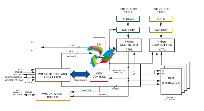
A functional block diagram of the VMIVME-5576 is
shown in Figure 1.
TRADEMARKS
The VMIC logo is a registered trademark of VMIC.
Other registered trademarks are the property of their
respective owners.
-
 Hirschmann RS20-1600M2T1SDAEHH03.1.02 Rail Switch
 -
 Hirschmann BRS30-24TX Industrial Rail Switch
 -
 Hirschmann RSPM20-4T14T1EV9HHS999.9.99 Managed Ethernet Switch
 -
 Hirschmann BELDEN RS40-0009CCCCSDAPHH09.0.14 / RS400009CCCCSDAPHH09014
 -
Hirschmann RS40 Rail Switch RS40-0009CCCCSDAE
-
 Hirschmann BELDEN RS30-0802T1T1SDAP / RS300802T1T1SDAP Fully Managed Layer 2 Compact Rail Switch
 -
 Hirschmann BELDEN RS20-0800M2M2SDAUHH / RS200800M2M2SDAUHH
 -
 Hirschmann EAGLE30-04022O6TT999SCCY9HSE3F Industrial Firewall Router Switch
 -
 Hirschmann RS20-1600T1T1SDAEHH09.0.14 RS20 Rail Mount Ethernet Switch
 -
 Hirschmann EAGLE0200T1T1TDDY90000HHE05.3.03 Industrial Security Router
 -
Hirschmann - BELDEN MIPP-AD-1L9P
-
 HIRSCHMANN RSPM20-4Z64Z6TV9HHS9 942 106-999 RAIL SAFETY SWITCH
 -
 HIRSCHMANN FIBEROPTIC MODULE FIP P/N: OZDFIPG3T
 -
 HIRSCHMANN RS20-1600M2M2SDAUHH Ethernet rack-mounted switch
 -
 HIRSCHMANN BELDEN RS20-0400T1T1SDAEHH04.0.01 / RS200400T1T1SDAEHH04001
 -
HIRSCHMANN MM2-4FXM3 MICE Media Module
-
HIRSCHMANN RS20-0800M2M2SDAE Industrial Ethernet Rail Switch
-
 Hirschmann RS20-2400T1T1SDAP / RS20-2400T1T1SDAPHH05.0.02
 -
 GE MLJ1005B010H00C MLJ Digital Synchromism Check
 -
 ALSTOM MICROTECH DX21-M2 Digital Excitation Controller
 -
HIRSCHMANN BRS20-1200ZZZZ-STCY99HHSES
-
 HIRSCHMANN MM3-4FXM2 MICE Media Module
 -
Hirschmann RSB20-0800T1T1SAABHH 8Port ENet Rail Switch RSB20
-
 Hirschmann MACH102-8TP Ethernet Switch
 -
 SAACKE DDZ-M marine steam pressure atomizer
 -
 SAACKE SKV-A marine rotary cup atomizer
 -
 SAACKE Seavis HMI05e
 -
 Kollmorgen MMC-SD-2.0-230 Servo Drive 100-240VAC 2KW 10A Output 3PH 100-240VAC
 -
 Kollmorgen Servo drive CR10550
 -
 Kollmorgen AKD-P01207-NACN-0054 Servo Driver
 -
 Kollmorgen S406M-CA-036 Servostar
 -
.png) Kollmorgen AKD-B02407-NAAN-0000 Digital Servo Drive
Kollmorgen AKD-B02407-NAAN-0000 Digital Servo Drive -
 Kollmorgen SERVOSTAR S406AM-CA Digital Servo Drive
 -
 KOLLMORGEN SERVOSTAR 603-AS SERVO AMPLIFIER_SERVOSTAR603AS_S60301
 -
Kollmorgen S700 Servo Controller (S70602-NANANA-NA)
-
 Kollmorgen MPK411 controller
 -
 KOLLMORGEN MMC-SD-1.3-460-D Smart Drive
 -
 KOLLMORGEN AKM21C-CKB2AA-00 / AKM21CCKB2AA00 Servomotor
 -
 BECKHOFF AX5106-0000-0200 | Digital Compact Servo Drives 1-channel
 -
 BECKHOFF C3620-0000 INDUSTRIAL COMPUTER (MOTORSHELVES)
 -
 Beckhoff EK1960-0000 TwinSAFE Compact Controller
 -
 Beckhoff C6930-0050 Control Cabinet Industrial PC
 -
 Beckhoff CP7711-0001-0030 Industrial Computer Detection
 -
 Beckhoff CX1001-0111 Embedded PC CPU Module
 -
 Beckhoff C6017-0020 | Ultra-compact Industrial PC
 -
 Beckhoff EK1322 | 2-port EtherCAT P junction with feed-in
 -
 Beckhoff CP2219-0010 Panel
 -
 BECKHOFF C6015-0020 ULTRA COMPACT INDUSTRIAL PC
 -
 BECKHOFF CX2030-0120/Standard CPU Module Embedded PC Windows PLC controller
 -
 Beckhoff CP7721-1090-0020 Panel PC
 -
 Beckhoff PC CPU Module CX5130-0175
 -
 Beckhoff C6920-0050 Control Cabinet
 -
 Beckhoff EL6631 EtherCAT 2-Port Communication Interface, Profinet RT Controller
 -
 Beckhoff CP6202-0001-0060 touch screen panel PC
 -
 Beckhoff CP3916-1002-0000 Multi-Touch Control Panel
 -
 Beckhoff EP1809-0021 | EtherCAT Box, 16-channel digital input, 24 V DC, 3 ms, M8Preferred type
 -
 Beckhoff CX8190 PLC Embedded Industrial PC Ethernet Controller
 -
 Beckhoff CX2100-0914 Power Supply for External
 -
 Beckhoff Automation CP6906-0001-0000 HMI
 -
 Beckhoff EP7342-0002 Module
 -
 Beckhoff CX1020-0112 / CX1100-0910 / CX1020-N010 / CX1100-0003 Windows CPU
 -
 Beckhoff EP7211-0034 EtherCAT Box 1 Channel Motion Interface
 -
 Beckhoff C6240-0030 Control cabinet Industrial PC
 -
 beckhoff motherboard CB1052-0004 CB1052-0004
 -
 Beckhoff AX2006-AS Servo Drive / Variable Frequency Drive
 -
BECKHOFF CP6207-0001-0020 NSMP
-
 Beckhoff C6930-1142-0060 Industrial Computer
 -
 Beckhoff FC7501-0000 interface card
 -
 Beckhoff CX5140-0175 Embedded PC PLC CPU CX5140 Industrial Controller
 -
 Beckhoff CP7802-1100-0010: High-End IP65 Control Panel with DVI/USB Extended Interface
 -
BECKHOFF CP3716-1058-0010 CONTROL PANEL
-
 Beckhoff AX8108-0000 Single-Axis Module
 -
 Beckhoff CU8851-0000 | USB extension, USB Extended 2.0 receiver box
 -
Beckhoff C6017-0030 | Ultra-compact Industrial PC
-
 Beckhoff CX1001-0120/CX10010120.cx1000-n001.cx1000-n000 System Overview
 -
 Beckhoff CPU Module CX5140-0155/4GB CPU Module
 -
 Beckhoff CP6533-0001-005: Built-in Panel PC with High-Definition Multi-Touch Control
 -
 Beckhoff EL5042 | EtherCAT Terminal, 2-channel encoder interface, BiSS® C
 -
 Beckhoff C6920-1080-0040: Premium Control Cabinet Industrial PC
 -
 Beckhoff C6920-0060 | Control cabinet Industrial PC
 -
 Beckhoff Embedded-PC CX5010-1121
 -
 Beckhoff CB3050-0010 Mainboard Motherboard
 -
 Beckhoff PLC module CX1020-0000 Basic CPU module (service phase)
 -
 Beckhoff CP7812-1056-0010 15" Multitouch Display Control Panel
 -
 Beckhoff CX5120-0115 /2GB Controller Module
 -
 Beckhoff CP7201-1000-0000 Industrial Panel PC
 -
 Beckhoff Servo Motor AM8061-0JH1-0000
 -
 BECKHOFF CP6503-0001-0050 Built-in Panel PC
 -
Beckhoff CP3919-0010 Display G190ETN01.2 19" PCT V04. Multi-touch Control Panel
-
 Beckhoff CX5110-0112-9020/000368201 Embedded PC Intel Atom Processor
 -
 Beckhoff AX8206-0000 Dual-Axis Module
 -
Beckhoff Nail Operating Terminal CP7032-1031-0010
-
Beckhoff AM8042-0EH1-0000 Servomotor 4.10 Nm (M0), F4 (87 mm)
-
 Beckhoff EK9300 Beckhoff CPU Module
 -
Beckhoff CP3224-0020 Multitouch-Panel-PC
-
 Beckhoff CP2712-0000 12.1" 24VDC Touch Screen WMD0
 -
 BECKHOFF CX5240-0195 / 0000289234 Embedded PC 40 GB CFast Card
 -
 Beckhoff CP6932-1000-0000 Control Panel
 -
 BECKHOFF CX5120-0121 PLC Module
 -
 Beckhoff EL3218 | EtherCAT Terminal, 8-channel analog input
 -
Beckhoff C6640-0050 | Control cabinet Industrial PC
-
 Beckhoff Cx5130-0120/4GB Embedded-PC
 -
 BECKHOFF CX2030-0122 PLC PROCESSOR
 -
 BECKHOFF CX5020-0122 Controller Module
 -
 Beckhoff CP3915-0000 Multitouch Panel
 -
 BECKHOFF EL3014 | EtherCAT Terminal
 -
 BECKHOFF Industrial Computer c6920-1057-0030
 -
 Beckhoff CX5130-0141/4GB CX5130-0141 Embedded PC
 -
 Beckhoff C6240-1052-0040 4-086-06-3073 Industrial Computer
 -
 Beckhoff CX5140-0135 /4GB High-Performance Embedded Industrial PC
 -
 Beckhoff C6515-1001-0000 Industrial PC
 -
 Beckhoff AX5103-0000-0200 - Digital Compact Servo Drives
 -
 Beckhoff CX2030-0130-1003/4GB Basic CPU module
 -
 Beckhoff AX8620-0000 Power Supply Module
 -
 Beckhoff CX9020-0111 module with
 -
 Beckhoff EL7332 PLC Module
 -
 BECKHOFF CP7709-0001-0020 HMI
 -
 Beckhoff CX5120-0155/2GB Embedded PC
 -
 BECKHOFF CP7037-1037-0010 OPERATOR INTERFACE TOUCHSCREEN
 -
 Beckhoff EK9000 | ModbusTCP/UDP Bus Coupler
 -
 Beckhoff Touch Panel Screen CP6020 -0000-0000
 -
 Beckhoff CX2020-0121 Module FAST Shipping
 -
 Beckhoff CX2030-0125 Basic CPU Module
 -
 Beckhoff CP3918-0000 Multi-Touch 18.5" Control Panel
 -
 Automotion LC4A00010 DC BL Motor Control, ATS, Sub Assy, SCP, 115VAC,
 -
 500T-115VAC - VAS ENGINEERING - DORIC 500 SERIES DIGITAL TEMP INDICATOR
 -
 Honeywell X-DCS2000/EN Digital Integrated System Manager 50/60Hz 100-240V #4
 -
 Kollmorgen S60600 Servostar600 606-Fan 4 kVA, 6 A, 3 X 230 - 480 V


