
A-BControlLogix AutoMax DCSNet and AutoMax Remote I/O Communication Interface Module
Important User Information
Because of the variety of uses for the products described in this publication, those responsible for the application and use of this control equipment must satisfy themselves that all necessary steps have been taken to assure that each application and use meets all performance and safety requirements, including any applicable laws, regulations, codes and standards. The illustrations, charts, sample programs and layout examples shown in this guide are intended solely for purposes of example. Since there are many variables and requirements associated with any particular installation, Rockwell Automation does not assume responsibility or liability (to include intellectual property liability) for actual use based upon the examples shown in this publication. Allen-Bradley publication SGI-1.1, Safety Guidelines for the Application, Installation and Maintenance of Solid-State Control (available from your local Rockwell Automation office), describes some important differences between solid-state equipment and electromechanical devices that should be taken into consideration when applying products such as those described in this publication. Reproduction of the contents of this copyrighted publication, in whole or part, without written permission of Rockwell Automation, is prohibited
Throughout this manual we use the following notes to make you aware of safety considerations:
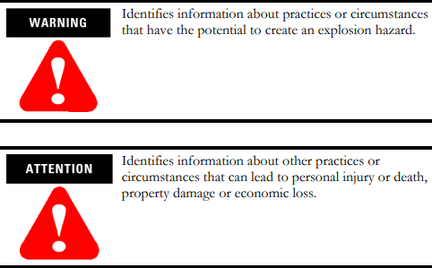
Warning and Attention statements help you to:
• identify a hazard
• avoid a hazard
• recognize the consequences
Understand Compliance to European Union Directive If this product bears the CE marking, it is approved for installation within the European Union and EEA regions. It has been designed and tested to meet the following directives.
EMC Directive This product is tested to meet Council Directive 89/336/EEC Electromagnetic Compatibility (EMC) and the following standards, in whole or in part, documented in a technical construction file:
• EN 50081-2 EMC - Generic Emission Standard, Part 2 - Industrial Environment
• EN 50082-2 EMC - Generic Immunity Standard, Part 2 - Industrial Environment This product is intended for use in an industrial environmen
Low Voltage Directive This product is tested to meet Council Directive 73/23/EEC Low Voltage, by applying the safety requirements of EN 61131-2 Programmable Controllers, Part 2 - Equipment Requirements and Tests. For specific information required by EN 61131-2, see the appropriate sections in this publication, as well as the following Allen-Bradley publications:
• Industrial Automation Wiring and Grounding Guidelines, publication 1770-4.1
• Automation Systems Catalog, publication B113 Open style devices must be provided with environmental and safety protection by proper mounting in enclosures designed for specific application conditions. See NEMA Standards publication 250 and IEC publication 529, as applicable, for explanations of the degrees of protection provided by different types of enclosure.
Enclosure and Environmental Requirements Specific To This Product The 56AMXN/B is NOT suitable for use in hazardous locations. This product must be mounted within a suitable system enclosure to prevent personal injury resulting from accessibility to live parts. The interior of this enclosure must be accessible only by the use of a tool. This industrial control equipment is intended to operate in a Pollution Degree 2 environment, in overvoltage category II applications, (as defined in IEC publication 664A) at altitudes up to 2000 meters without derating.
Preventing Electrostatic Discharge The 56AMXN/B module is sensitive to electrostatic discharge.

Electrostatic discharge can damage integrated circuits or semiconductors if you touch backplane connector pins. Follow these guidelines when you handle the module:
• Touch a grounded object to discharge static potential
• Wear an approved wrist-strap grounding device
• Do not touch the backplane connector or connector pins
• Do not touch circuit components inside the module
• If available, use a static-safe work station
• When not in use, keep the module in its static-shield packaging
For additional information refer to publication 1770-4.1, Industrial Automation Wiring and Grounding Guidelines.
Identify Module Features Refer to the following figure to identify the hardware components of the 56AMXN/B module
The module has:
• A label to indicate that it is a scanner for AutoMax DCSNet and remote I/O
• A 4-character scrolling display (XXXX)
• 3 LEDs, labelled NET, CLX, and OK, to indicate the status of the network, the connection to the ControlLogix processor, and its own internal state
• a 9-pin D-shell connector to connect to the DCS or remote I/O network
• switches at the top of the module to set the mode of operation and the drop number and drop depth
Set the Network Type and Node Address Switches Before you install the module, you must set the network type, drop number and drop depth using the switches at the top of the module. The two switches at the left set the drop depth, the two at the right set the drop number. The following table shows how to set the switches for each mode of operation.
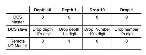
For example, to configure the 56AMXN/B as a DCS slave with drop number 17, drop depth 5, set the switches to 0, 5, 1, and 7 from left to right. Any other settings are invalid and result in the module going into “Thumbwheel test” mode. In thumbwheel test mode, the display shows the current switch settings. It doesn’t go out of thumbwheel test mode until you cycle power. In thumbwheel test mode, the 56AMXN/B initially displays “Thumb Test Mode” on the 4-character display, displays the switch settings for 5 seconds, then resumes displaying “Thumb Test Mode” For DCS slave operation, if the drop number and drop depth are individually valid but the combination results in invalid drop numbers (for example, drop number 55, drop depth 2), the module displays an error message on the 4-character display but does not enter Thumbwheel test mode
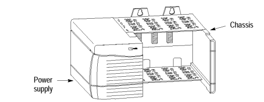
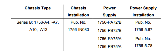
Prepare the Chassis for Module Installation Before you install the 56AMXN/B module, you must install and connect a ControlLogix chassis and power supply.
For information on installing these products, refer to the publications listed in the following table
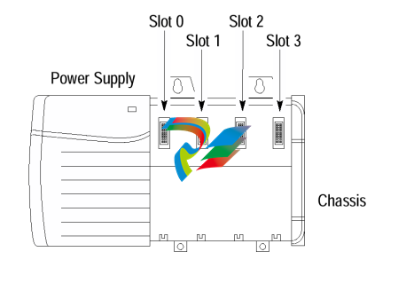
Determine Module Slot Location The figure below shows chassis slot numbering in a 4-slot chassis. Slot 0 is the first slot and is always the leftmost slot in the rack (the first slot to the right of the power supply). You can use any size ControlLogix chassis and install the module in any slot. You can also install multiple 56AMXN/B modules in the same chassis. You can install as many modules as your power supply can accommodate (i.e., number for which the power supply is rated)
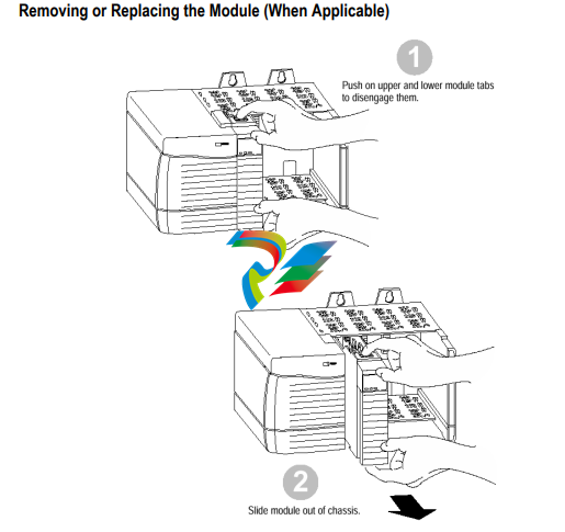
Installing or Removing the Module While Power Is Applied Versions of the 56AMXN hardware prior to O-57677-1 do NOT support removal and insertion under power. The hardware version can be identified by looking for a sticker with the part number O-57677-1 or above on the module’s printed circuit (near the serial number – you do not need to disassemble the 56AMXN to find the sticker). Modules with no stickers are hardware version O-57677 and do NOT support removal and insertion under power For hardware versions O-57677-1 and above, you can install or remove the module while chassis power is applied if you observe the following precautions.
When you insert or remove a module while backplane power is on, an electrical arc may occur. An electrical arc can cause personal injury or property damage by: • sending an erroneous signal to your system’s actuators causing unintended machine motion or loss of process control. • causing an explosion in a hazardous environment. Repeated electrical arcing causes excessive wear to contacts on both the module and its mating connector. Worn contacts may create electrical resistance that can affect module operation.
Do not force the module into the backplane connector. If you cannot seat the module with firm pressure, check the alignment. Forcing the module into the chassis can damage the backplane connector or the module
If you are replacing an existing module with an identical one, and you want to resume identical system operation, you must install the new module in the same slot. You must also set the switches to the same settings and run the configuration program and download the appropriate configuration to the module.
Wire the Connector for the AutoMax Network Use a drop cable, 612574-36R, available through Rockwell Automation Systems Business, and passive tap M/N 57C380 to connect the module to the coaxial network cable. This cable turns down and has a ferrite to reduce EMI. This cable must be used in CE applications. You can also use drop cable 612403-036R but it points up. The drop cable is a 3-foot long multi-conductor cable with 9-pin D-shell connectors at each end. Connect one end to the connector on the module and the other end to the passive tap. The passive tap has two BNC connectors for connection to the coaxial cables and terminating loads. The network coaxial cable must be terminated with 75 ohm terminating loads attached to the taps at the physical ends of the network. There should be two and only two terminators on the network. For DCS, the network cable can be RG-59/U or RG-11/U. For remote I/O, the cable must be RG-59/U. Apply Chassis Power Turn the rack power supply on.
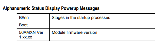
Check Power Supply and Module Status The rack power supply indicator should be green. The module OK LED should be solid red, then solid green. The alphanumeric display shows the following messages at powerup.
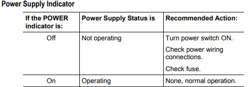
Troubleshooting the Power Supply If the alphanumeric indicator on the 56AMXN/B module does not cycle through these messages on powerup, refer to the following table and to the Troubleshooting section that follows.
OK LED – Module Health A bicolor OK LED indicates module health. A red LED indicates that module startup diagnostics have failed or a major module fault such as watchdog bite or jabber inhibit has occurred. Green indicates that the card has passed all power-up diagnostics and is functioning normally. This LED is red during powerup. If all three LEDs are solid red and the 4-character display shows something like M#66, this indicates that a fatal error has occurred. Refer to the User Guide for information on clearing fatal errors. Where to Find Information on Configuring Your 56AMXN/B Module Now that you have installed your AutoMax DCS/RIO module, you must configure it. For this information, refer to the configuration chapters of your 56AMXN User’s Guide, publication 56AMXN-UM002A-EN-P. This manual is supplied on the 56AMXN/B distribution CD. The CD also contains the Adobe PDF reader.
-
 Hirschmann RS20-1600M2T1SDAEHH03.1.02 Rail Switch
 -
 Hirschmann BRS30-24TX Industrial Rail Switch
 -
 Hirschmann RSPM20-4T14T1EV9HHS999.9.99 Managed Ethernet Switch
 -
 Hirschmann BELDEN RS40-0009CCCCSDAPHH09.0.14 / RS400009CCCCSDAPHH09014
 -
Hirschmann RS40 Rail Switch RS40-0009CCCCSDAE
-
 Hirschmann BELDEN RS30-0802T1T1SDAP / RS300802T1T1SDAP Fully Managed Layer 2 Compact Rail Switch
 -
 Hirschmann BELDEN RS20-0800M2M2SDAUHH / RS200800M2M2SDAUHH
 -
 Hirschmann EAGLE30-04022O6TT999SCCY9HSE3F Industrial Firewall Router Switch
 -
 Hirschmann RS20-1600T1T1SDAEHH09.0.14 RS20 Rail Mount Ethernet Switch
 -
 Hirschmann EAGLE0200T1T1TDDY90000HHE05.3.03 Industrial Security Router
 -
Hirschmann - BELDEN MIPP-AD-1L9P
-
 HIRSCHMANN RSPM20-4Z64Z6TV9HHS9 942 106-999 RAIL SAFETY SWITCH
 -
 HIRSCHMANN FIBEROPTIC MODULE FIP P/N: OZDFIPG3T
 -
 HIRSCHMANN RS20-1600M2M2SDAUHH Ethernet rack-mounted switch
 -
 HIRSCHMANN BELDEN RS20-0400T1T1SDAEHH04.0.01 / RS200400T1T1SDAEHH04001
 -
HIRSCHMANN MM2-4FXM3 MICE Media Module
-
HIRSCHMANN RS20-0800M2M2SDAE Industrial Ethernet Rail Switch
-
 Hirschmann RS20-2400T1T1SDAP / RS20-2400T1T1SDAPHH05.0.02
 -
 GE MLJ1005B010H00C MLJ Digital Synchromism Check
 -
 ALSTOM MICROTECH DX21-M2 Digital Excitation Controller
 -
HIRSCHMANN BRS20-1200ZZZZ-STCY99HHSES
-
 HIRSCHMANN MM3-4FXM2 MICE Media Module
 -
Hirschmann RSB20-0800T1T1SAABHH 8Port ENet Rail Switch RSB20
-
 Hirschmann MACH102-8TP Ethernet Switch
 -
 SAACKE DDZ-M marine steam pressure atomizer
 -
 SAACKE SKV-A marine rotary cup atomizer
 -
 SAACKE Seavis HMI05e
 -
 Kollmorgen MMC-SD-2.0-230 Servo Drive 100-240VAC 2KW 10A Output 3PH 100-240VAC
 -
 Kollmorgen Servo drive CR10550
 -
 Kollmorgen AKD-P01207-NACN-0054 Servo Driver
 -
 Kollmorgen S406M-CA-036 Servostar
 -
.png) Kollmorgen AKD-B02407-NAAN-0000 Digital Servo Drive
Kollmorgen AKD-B02407-NAAN-0000 Digital Servo Drive -
 Kollmorgen SERVOSTAR S406AM-CA Digital Servo Drive
 -
 KOLLMORGEN SERVOSTAR 603-AS SERVO AMPLIFIER_SERVOSTAR603AS_S60301
 -
Kollmorgen S700 Servo Controller (S70602-NANANA-NA)
-
 Kollmorgen MPK411 controller
 -
 KOLLMORGEN MMC-SD-1.3-460-D Smart Drive
 -
 KOLLMORGEN AKM21C-CKB2AA-00 / AKM21CCKB2AA00 Servomotor
 -
 BECKHOFF AX5106-0000-0200 | Digital Compact Servo Drives 1-channel
 -
 BECKHOFF C3620-0000 INDUSTRIAL COMPUTER (MOTORSHELVES)
 -
 Beckhoff EK1960-0000 TwinSAFE Compact Controller
 -
 Beckhoff C6930-0050 Control Cabinet Industrial PC
 -
 Beckhoff CP7711-0001-0030 Industrial Computer Detection
 -
 Beckhoff CX1001-0111 Embedded PC CPU Module
 -
 Beckhoff C6017-0020 | Ultra-compact Industrial PC
 -
 Beckhoff EK1322 | 2-port EtherCAT P junction with feed-in
 -
 Beckhoff CP2219-0010 Panel
 -
 BECKHOFF C6015-0020 ULTRA COMPACT INDUSTRIAL PC
 -
 BECKHOFF CX2030-0120/Standard CPU Module Embedded PC Windows PLC controller
 -
 Beckhoff CP7721-1090-0020 Panel PC
 -
 Beckhoff PC CPU Module CX5130-0175
 -
 Beckhoff C6920-0050 Control Cabinet
 -
 Beckhoff EL6631 EtherCAT 2-Port Communication Interface, Profinet RT Controller
 -
 Beckhoff CP6202-0001-0060 touch screen panel PC
 -
 Beckhoff CP3916-1002-0000 Multi-Touch Control Panel
 -
 Beckhoff EP1809-0021 | EtherCAT Box, 16-channel digital input, 24 V DC, 3 ms, M8Preferred type
 -
 Beckhoff CX8190 PLC Embedded Industrial PC Ethernet Controller
 -
 Beckhoff CX2100-0914 Power Supply for External
 -
 Beckhoff Automation CP6906-0001-0000 HMI
 -
 Beckhoff EP7342-0002 Module
 -
 Beckhoff CX1020-0112 / CX1100-0910 / CX1020-N010 / CX1100-0003 Windows CPU
 -
 Beckhoff EP7211-0034 EtherCAT Box 1 Channel Motion Interface
 -
 Beckhoff C6240-0030 Control cabinet Industrial PC
 -
 beckhoff motherboard CB1052-0004 CB1052-0004
 -
 Beckhoff AX2006-AS Servo Drive / Variable Frequency Drive
 -
BECKHOFF CP6207-0001-0020 NSMP
-
 Beckhoff C6930-1142-0060 Industrial Computer
 -
 Beckhoff FC7501-0000 interface card
 -
 Beckhoff CX5140-0175 Embedded PC PLC CPU CX5140 Industrial Controller
 -
 Beckhoff CP7802-1100-0010: High-End IP65 Control Panel with DVI/USB Extended Interface
 -
BECKHOFF CP3716-1058-0010 CONTROL PANEL
-
 Beckhoff AX8108-0000 Single-Axis Module
 -
 Beckhoff CU8851-0000 | USB extension, USB Extended 2.0 receiver box
 -
Beckhoff C6017-0030 | Ultra-compact Industrial PC
-
 Beckhoff CX1001-0120/CX10010120.cx1000-n001.cx1000-n000 System Overview
 -
 Beckhoff CPU Module CX5140-0155/4GB CPU Module
 -
 Beckhoff CP6533-0001-005: Built-in Panel PC with High-Definition Multi-Touch Control
 -
 Beckhoff EL5042 | EtherCAT Terminal, 2-channel encoder interface, BiSS® C
 -
 Beckhoff C6920-1080-0040: Premium Control Cabinet Industrial PC
 -
 Beckhoff C6920-0060 | Control cabinet Industrial PC
 -
 Beckhoff Embedded-PC CX5010-1121
 -
 Beckhoff CB3050-0010 Mainboard Motherboard
 -
 Beckhoff PLC module CX1020-0000 Basic CPU module (service phase)
 -
 Beckhoff CP7812-1056-0010 15" Multitouch Display Control Panel
 -
 Beckhoff CX5120-0115 /2GB Controller Module
 -
 Beckhoff CP7201-1000-0000 Industrial Panel PC
 -
 Beckhoff Servo Motor AM8061-0JH1-0000
 -
 BECKHOFF CP6503-0001-0050 Built-in Panel PC
 -
Beckhoff CP3919-0010 Display G190ETN01.2 19" PCT V04. Multi-touch Control Panel
-
 Beckhoff CX5110-0112-9020/000368201 Embedded PC Intel Atom Processor
 -
 Beckhoff AX8206-0000 Dual-Axis Module
 -
Beckhoff Nail Operating Terminal CP7032-1031-0010
-
Beckhoff AM8042-0EH1-0000 Servomotor 4.10 Nm (M0), F4 (87 mm)
-
 Beckhoff EK9300 Beckhoff CPU Module
 -
Beckhoff CP3224-0020 Multitouch-Panel-PC
-
 Beckhoff CP2712-0000 12.1" 24VDC Touch Screen WMD0
 -
 BECKHOFF CX5240-0195 / 0000289234 Embedded PC 40 GB CFast Card
 -
 Beckhoff CP6932-1000-0000 Control Panel
 -
 BECKHOFF CX5120-0121 PLC Module
 -
 Beckhoff EL3218 | EtherCAT Terminal, 8-channel analog input
 -
Beckhoff C6640-0050 | Control cabinet Industrial PC
-
 Beckhoff Cx5130-0120/4GB Embedded-PC
 -
 BECKHOFF CX2030-0122 PLC PROCESSOR
 -
 BECKHOFF CX5020-0122 Controller Module
 -
 Beckhoff CP3915-0000 Multitouch Panel
 -
 BECKHOFF EL3014 | EtherCAT Terminal
 -
 BECKHOFF Industrial Computer c6920-1057-0030
 -
 Beckhoff CX5130-0141/4GB CX5130-0141 Embedded PC
 -
 Beckhoff C6240-1052-0040 4-086-06-3073 Industrial Computer
 -
 Beckhoff CX5140-0135 /4GB High-Performance Embedded Industrial PC
 -
 Beckhoff C6515-1001-0000 Industrial PC
 -
 Beckhoff AX5103-0000-0200 - Digital Compact Servo Drives
 -
 Beckhoff CX2030-0130-1003/4GB Basic CPU module
 -
 Beckhoff AX8620-0000 Power Supply Module
 -
 Beckhoff CX9020-0111 module with
 -
 Beckhoff EL7332 PLC Module
 -
 BECKHOFF CP7709-0001-0020 HMI
 -
 Beckhoff CX5120-0155/2GB Embedded PC
 -
 BECKHOFF CP7037-1037-0010 OPERATOR INTERFACE TOUCHSCREEN
 -
 Beckhoff EK9000 | ModbusTCP/UDP Bus Coupler
 -
 Beckhoff Touch Panel Screen CP6020 -0000-0000
 -
 Beckhoff CX2020-0121 Module FAST Shipping
 -
 Beckhoff CX2030-0125 Basic CPU Module
 -
 Beckhoff CP3918-0000 Multi-Touch 18.5" Control Panel
 -
 Automotion LC4A00010 DC BL Motor Control, ATS, Sub Assy, SCP, 115VAC,
 -
 500T-115VAC - VAS ENGINEERING - DORIC 500 SERIES DIGITAL TEMP INDICATOR
 -
 Honeywell X-DCS2000/EN Digital Integrated System Manager 50/60Hz 100-240V #4
 -
 Kollmorgen S60600 Servostar600 606-Fan 4 kVA, 6 A, 3 X 230 - 480 V


