A-BControlLogix AutoMax DCSNet and AutoMax Remote I/O Communication Interface Module
Important User Information
Because of the variety of uses for the products described in this publication, those responsible for the application and use of this control equipment must satisfy themselves that all necessary steps have been taken to assure that each application and use meets all performance and safety requirements, including any applicable laws, regulations, codes and standards. The illustrations, charts, sample programs and layout examples shown in this guide are intended solely for purposes of example. Since there are many variables and requirements associated with any particular installation, Rockwell Automation does not assume responsibility or liability (to include intellectual property liability) for actual use based upon the examples shown in this publication. Allen-Bradley publication SGI-1.1, Safety Guidelines for the Application, Installation and Maintenance of Solid-State Control (available from your local Rockwell Automation office), describes some important differences between solid-state equipment and electromechanical devices that should be taken into consideration when applying products such as those described in this publication. Reproduction of the contents of this copyrighted publication, in whole or part, without written permission of Rockwell Automation, is prohibited
Throughout this manual we use the following notes to make you aware of safety considerations:
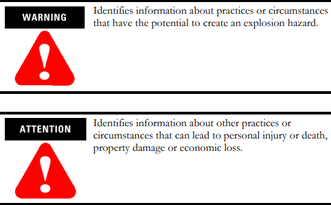
Warning and Attention statements help you to:
• identify a hazard
• avoid a hazard
• recognize the consequences
Understand Compliance to European Union Directive If this product bears the CE marking, it is approved for installation within the European Union and EEA regions. It has been designed and tested to meet the following directives.
EMC Directive This product is tested to meet Council Directive 89/336/EEC Electromagnetic Compatibility (EMC) and the following standards, in whole or in part, documented in a technical construction file:
• EN 50081-2 EMC - Generic Emission Standard, Part 2 - Industrial Environment
• EN 50082-2 EMC - Generic Immunity Standard, Part 2 - Industrial Environment This product is intended for use in an industrial environmen
Low Voltage Directive This product is tested to meet Council Directive 73/23/EEC Low Voltage, by applying the safety requirements of EN 61131-2 Programmable Controllers, Part 2 - Equipment Requirements and Tests. For specific information required by EN 61131-2, see the appropriate sections in this publication, as well as the following Allen-Bradley publications:
• Industrial Automation Wiring and Grounding Guidelines, publication 1770-4.1
• Automation Systems Catalog, publication B113 Open style devices must be provided with environmental and safety protection by proper mounting in enclosures designed for specific application conditions. See NEMA Standards publication 250 and IEC publication 529, as applicable, for explanations of the degrees of protection provided by different types of enclosure.
Enclosure and Environmental Requirements Specific To This Product The 56AMXN/B is NOT suitable for use in hazardous locations. This product must be mounted within a suitable system enclosure to prevent personal injury resulting from accessibility to live parts. The interior of this enclosure must be accessible only by the use of a tool. This industrial control equipment is intended to operate in a Pollution Degree 2 environment, in overvoltage category II applications, (as defined in IEC publication 664A) at altitudes up to 2000 meters without derating.
Preventing Electrostatic Discharge The 56AMXN/B module is sensitive to electrostatic discharge.

Electrostatic discharge can damage integrated circuits or semiconductors if you touch backplane connector pins. Follow these guidelines when you handle the module:
• Touch a grounded object to discharge static potential
• Wear an approved wrist-strap grounding device
• Do not touch the backplane connector or connector pins
• Do not touch circuit components inside the module
• If available, use a static-safe work station
• When not in use, keep the module in its static-shield packaging
For additional information refer to publication 1770-4.1, Industrial Automation Wiring and Grounding Guidelines.
Identify Module Features Refer to the following figure to identify the hardware components of the 56AMXN/B module
The module has:
• A label to indicate that it is a scanner for AutoMax DCSNet and remote I/O
• A 4-character scrolling display (XXXX)
• 3 LEDs, labelled NET, CLX, and OK, to indicate the status of the network, the connection to the ControlLogix processor, and its own internal state
• a 9-pin D-shell connector to connect to the DCS or remote I/O network
• switches at the top of the module to set the mode of operation and the drop number and drop depth
Set the Network Type and Node Address Switches Before you install the module, you must set the network type, drop number and drop depth using the switches at the top of the module. The two switches at the left set the drop depth, the two at the right set the drop number. The following table shows how to set the switches for each mode of operation.


.png)


