
galilmcEthernet/RS232 Accelera Series, 1–8 axes
Product Description
The DMC-40x0 motion controller is Galil’s highest
performance, stand-alone motion controller. It
belongs to Galil’s latest generation motion controller
family: the Accelera Series, which accepts encoder
inputs up to 22 MHz, provides servo update rates
as high as 32 kHz, and processes commands in as fast
as 40 microseconds—10 times the speed of prior
generation controllers.
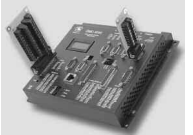
The DMC-40x0 is a fullfeatured motion controller
packaged with optional
multi-axis drives in a compact,metal enclosure.The
unit operates stand-alone
or interfaces to a PC with
Ethernet 10/100Base-T
or RS232.The controller
includes optically isolated
I/O, high-power outputs capable of driving brakes or
relays, and analog inputs for interfacing to analog
sensors.The DMC-40x0 controller and drive unit accepts
power from a single 20–80 VDC source.
The DMC-40x0 is available in one through eight axis
formats, and each axis is user-configurable for stepper
or servo motor operation. Standard programming
features include PID compensation with velocity and
acceleration feedforward, multitasking for simultaneously running up to eight programs, and I/O processing
commands for synchronizing motion with external
events. Modes of motion include point-to-point positioning, position tracking, jogging, linear and circular
interpolation,contouring, electronic gearing and ECAM.
Like all Galil controllers, the DMC-40x0 controllers use
Galil’s popular, English-like command language, which
makes them very easy to program. Galil’s WSDK servo
design software further simplifies system set-up with
“one-button” servo tuning and real-time display of
position and velocity information
Features
■ Packaged controller in 1 through 8 axis versions:
DMC-40x0 where x=1,2,3,4,5,6,7,8 axes
■ (1) 10/100BASE-T Ethernet port
(2) RS232 ports up to 115 kbaud
■ User-configurable for stepper or servo motors on any
combination of axes. Optional sinusoidal commutation
for brushless servo motors.
■ Accepts up to 22 MHz encoder frequencies for servos.
Outputs pulses up to6 MHz for steppers
■ PID compensation with velocity and acceleration feedforward, integration limits, notch filter and low-pass filter
■ Modes of motion include jogging, point-to-point positioning, contouring, linear and circular interpolation, electronic
gearing and ECAM. Features ellipse scaling, slow-down
around corners, infinite segment feed and feedrate override
■ Over 200 English-like commands including conditional
statements and event triggers
■ Non-volatile memory for programs,variables and arrays.
Multitasking for concurrent execution of up toeight
programs
■ Optically isolated home input and forward and reverse
limits for every axis.
■ Uncommitted, isolated inputs and isolated outputs
1- through 4-axis models: 8 inputs and 8 outputs
5- through 8-axis models: 16 inputs and 16 outputs
■ Isolated, high-power outputs for driving brakes or relays
■ High speed position latch for each axis and output compare
■ 8uncommitted analog inputs
■ 32 additional 3.3 V I/O (5 V option)
■ 2line x 8 character LCD
■ Dual encoder inputs for each axis
■ Accepts single 20–80 VDC input
■ Available with internal stepper and servo drives.
Or, connect to external drives of any power range
■ Communication drivers for all current versions of
Windows XP, .NET, and Linux
■ Custom hardware and firmware options available
Ethernet/RS232 Accelera Series, 1–8 axes
Specifications
System Processor
■ RISC-based, clock multiplying processor with DSP functions
Communications Interface
■ (1) 10/100BASE-T Ethernet port
■ (2) RS232 ports up to 115 kbaud
Commands are sent in ASCII. A binary communication mode is also
available as a standard feature
Modes of Motion:
■ Point-to-point positioning
■ Position Tracking
■ Jogging
■ 2D Linear and Circular Interpolation with feedrate override
■ Linear Interpolation for up to 8 axes
■ Tangential Following
■ Helical
■ Electronic Gearing with multiple masters and ramp-to-gearing
■ Gantry Mode
■ Electronic Cam
■ Contouring
■ Teach and playback
Memory
■ Program memory size—2000 lines × 80 characters
■ 510 variables
■ 16,000 total arrayelements in up to30 arrays
Filter
■ PID (proportional-integral-derivative) with velocity and acceleration
feedforward
■ Notch filter and low-pass filter
■ Dual-loop control for backlash compensation
■ Velocity smoothing to minimize jerk
■ Integration limit
■ Torque limit
■ Offset adjustment
Kinematic Ranges
■ Position: 32 bit (±2.15 billion counts per move; automatic rollover;
no limit in jog or vector modes)
■ Velocity: Up to 22 million counts/sec for servo motors
■ Acceleration: Up to 1 billion counts/sec2
Uncommitted I/O
ISOLATED ISOLATED ANALOG 3.3 V
INPUTS OUTPUTS INPUTS I/O
DMC-4010 thru -4040 8 8 8 32
DMC-4050 thru -4080 16 16 8 32
High Speed Position Latch
■ Uncommitted inputs 1-4 latch A,B,C,D and 9-12 latch E, F, G, H axes
(latches within 40 microseconds with optoisolation)
Dedicated Inputs (per axis)
■ Main encoder inputs—Channel A, A-, B,B-,I, I- (±12 V or TTL)
■ Dual encoder (for axes configured as servo)—Channel A, A-, B, B-
■ Forward and reverse limit inputs—optoisolated
■ Home input—optoisolated
■ Selectable high-speed position latch input—optoisolated
■ Selectable abort input for each axis—optoisolated
Dedicated Outputs (per axis)
■ Analog motor command output with 16-bit DAC resolution
■ Pulse and direction output for step motors
■ PWM output also available for servo amplifiers
■ Amplifier enable output
■ Error output (per set of 4 axes)
■ High-speed position compare output (per set of 4 axes)
Minimum Servo Loop Update Time
STANDARD -FAST*
■ 1–2 axes: 62 µsec 31 µsec
■ 3–4 axes:125 µsec 62 µsec
■ 5–6 axes:156 µsec 94 µsec
■ 7–8 axes: 187 µsec 125 µsec
Maximum Encoder Feedback Rate
■ 22 MHz
Maximum Stepper Rate
■ 6 MHz (Full, half or microstep)
Power Requirements
■ 20–80 VDC
Environmental
■ Operating temperature: 0–70º C
■ Humidity: 20–95% RH, non-condensing
Mechanical
■ 1- thru 4-axis: 8.1" × 7.25" × 1.72"
5- thru 8-axis: 11.5" × 7.25" × 1.72"
Ethernet/RS232 Accelera Series, 1–8 axes
Instruction Set
Servo Motor
AF Analog feedback
AG* Set AMP-43040 gain
AU* Set current loop gain
AW* Report AMP-43040 bandwidth
DV Dual loop operation
FA Acceleration feedforward
FV Velocity feedforward
IL Integrator limit
IT Independent time constant
KD Derivative constant
KI Integrator constant
KP Proportional constant
NB Notch bandwidth
NF Notch frequency
NZ Notch zero
OF Offset
PL Pole
SH Servo here
TL Torque limit
TM Sample time
Stepper Motor
DE Define encoder position
DP Define referenceposition
KS Stepper motor smoothing
MT Motor type
QS Error magnitude
RP Report commanded position
TD Step counts output
TP Tell position of encoder
YA Step drive resolution
YB Step motor resolution
YC Encoder resolution
YR Error correction
YS Stepper position maintenance
Brushless Motor
BA Brushless axis
BB Brushless phase
BC Brushless calibration
BD Brushless degrees
BI Brushless inputs
BM Brushless modulo
BO Brushless offset
BS Brushless setup
BZ Brushless zero
I/O
AL Arm latch
CB Clear bit
CO Configure I/O points
II Input interrupt
OB Define output bit
OC Output compare function
OP Output port
SB Set bit
@IN[x] State of digital input x
@OUT[x] Stateof digital output x
@AN[x] Value of analog input x
System Configuration
BN Burn parameters
BP Burn program
BR* Brush motor enable
BS* Brushless set-up
BV Burn variables and arrays
CE Configure encoder type
CN Configure switches
CO Configure I/O points
CW Data adjustment bit
DE Define dual encoder position
DP Define position
DR Data record update rate
EO Echo off
HS Handle switch
IA Set IP address
IH Internet handle
IT Independent smoothing
ˆLˆK Program protect
LZ Leading zeros format
MB ModBus
MO Motor off
MT Motor type
PF Position format
PW Password
QD Download array
QU Upload array
RS Reset
ˆRˆS Master reset
SM Subnet mask
VF Variable format
Math Functions
@SIN[x] Sine of x
@COS[x] Cosine of x
@COM[x] 1’s complementof x
@ASIN[x] Arc sine of x
@ACOS[x] Arc cosine of x
@ATAN[x] Arc tangent of x
@ABS[x] Absolutevalue of x
@FRAC[x] Fraction portion of x
@INT[x] Integer portion of x
@RND[x] Round of x
@SQR[x] Square root of x
% Modulus operator
Interrogation
ID AMP ID
LA List arrays
LL List labels
LS List program
LV List variables
MG Message command
QH* Query hall state
QR Data record
QZ Return data record information
RP Report command position
RL Report latch
ˆRˆV Firmware revision information
SC Stop code
TA* Tell AMP-43040 status
Interrogation (cont.)
TB Tell status
TC Tell error code
TD Tell dual encoder
TE Tell error
TI Tell input
TP Tell position
TR Trace program
TS Tell switches
TT Tell torque
TV Tell velocity
Programming
BK Breakpoint
DA Deallocate variables/arrays
DL Download program
DM Dimension arrays
ED Edit program
ELSE Conditional statement
ENDIF End of cond.statement
EN End program
HX Halt execution
IF If statement
IN Input variable
JP Jump
JS Jump to subroutine
NO No-operation—for comments
RA Record array
RC Record interval
RD Record data
REM Remark program
UL Upload program
ZA Data record variables
ZS Zerostack
‘ Comment
Error Control
BL Backward software limit
ER Error limit
FL Forward software limit
LD Limit disable
OA Encoder failure
OE Off-on-error function
OT Encoder failure period
OV Encoder failure voltage
SD Limit deceleration
TL Torque limit
TW Timeout for in-position
Trippoint
AD After distance
AI After input
AM After motion profiler
AP After absolute position
AR After relative distance
AS At speed
AT After time
AV After vector distance
MC Motion complete
MF After motion—forward
MR After motion—reverse
WT Wait for time
Independent Motion
AB Abort motion
AC Acceleration
BG Begin motion
DC Deceleration
FE Find edge
FI Find index
HM Home
HV Home speed
IP Increment position
IT Smoothing time constant
JG Jog mode
PA Position absolute
PR Position relative
PT Position tracking
SD Switch deceleration
SP Speed
ST Stop
Contour Mode
CD Contour data
CM Contour mode
DT Contour time interval
ECAM/Gearing
EA ECAM master
EB Enable ECAM
EC ECAM table index
EG ECAM go
EM ECAM cycle
EP ECAM interval
EQ Disengage ECAM
ET ECAM table entry
EW ECAM widen
EY ECAM cycle counter
GA Master axis for gearing
GD Engagement distance for gearing
GM Gantry mode
GP Correction for gearing
GR Gear ratio for gearing
Vector/Linear Interpolation
CA Define vector plane
CR Circular interpolation move
CS Clear motion sequence
ES Ellipse scaling
IT Smoothing time constant
LE Linear interpolation end
LI Linear interpolation segment
LM Linear interpolation mode
ST Stop motion
TN Tangent
VA Vector acceleration
VD Vector deceleration
VE Vector sequence end
VM Coordinated motion mode
VP Vector position
VR Vector speed ratio
VS Vector speed
VV Vector Velocity
Ethernet/RS232 Accelera Series, 1–8 axes
RS-232 Main Port
9-pin; Male connector and cable
1 NC
2 Transmit data-output
3 Receive data-input
4 NC
5 Ground
6 NC
7 Clear to Send-input
8 Request to Send-output
9 NC
RS232 Auxiliary Port
9-pin; Female connector and cable
1 NC
2 Receive data-input
3 Transmit data-output
4 NC
5 Ground
6 NC
7 Request toSend-output
8 Clear to Send-input
9 5 V
Ethernet 10/100Base-T
RJ-45 connector
Connectors—I/O
J1 Amplifier I/O Axes A thru D
44-pin Hi-density Male D-sub
1 Reserved
2 PWM C/Step C
3 Reserved
4 Reserved
5 Sign C/Dir C
6 Reserved
7 Amp enable A
8 Amp enable D
9 NC
10 -12V out
11 Motor command B
12 Reserved
13 NC
14 NC
15 +5V out
16 PWM A/Step A
17 Reserved
18 PWM D/Step D
19 Sign A/Dir A
20 Reserved
21 Sign D/Dir D
22 Amp Enable Common-1
23 Amp Enable C
24 NC
25 +12V out
26 Reserved
27 Motor command C
28 Reserved
29 NC
30 NC
31 PWM B/Step B
32 Reserved
33 Ground
34 Sign B/Dir B
35 Reserved
36 Ground
37 Amp enable B
38 Amp Enable Common-2
39 Ground
40 Motor command A
41 Reserved
42 Motor command D
43 Ground
44 NC
J1 Amplifier I/O Axes E thru H
44-pin Hi-density Male D-sub
1 Reserved
2 PWM G/Step G
3 Reserved
4 Reserved
5 Sign G/Dir G
6 Reserved
7 Amp enable E
8 Amp enable H
9 NC
10 -12V out
11 Motor command F
12 Reserved
13 NC
14 NC
15 +5V out
16 PWM E/Step E
17 Reserved
18 PWM H/Step H
19 Sign E/Dir E
20 Reserved
21 Sign H/Dir H
22 Amp Enable Common-1
23 Amp Enable G
24 NC
25 +12V out
26 Reserved
27 Motor command G
28 Reserved
29 NC
30 NC
31 PWM F/Step F
32 Reserved
33 Ground
34 Sign F/Dir F
35 Reserved
36 Ground
37 Amp enable F
38 Amp Enable Common-2
39 Ground
40 Motor command E
41 Reserved
42 Motor command H
43 Ground
44 NC
J2 Power*
6-pin
1 Ground
2 +VM (20 V–80 V)
3 Ground
4 +VM (20 V–80 V)
5 Ground
6 +VM (20 V–80 V)
JA1, JB1, JC1, JD1
Motor Output
4-pin
1 Motor Phase C
2 NC
3 Motor Phase B
4 Motor Phase A
Connectors—
Amplifier Board
AMP-43040
* Note: Power can be input through either of the amplifier connectors to power the entire unit due to power pass-thru connectors that connect input power to
all modules. For 5- through 8-axis units with two different types of amplifiers, the lower of the maximum voltages is the maximum rating for the unit.
However, if you need different voltages, you can specify the ISAMP and/or ISCNTL option to separate the various power inputs.
When using the AMP-43140 with a power supply lower than +/-20 Volts, a separate supply of 20 –80 VDC must be input to the 2-pin
connector on the side of the DMC-40X0 or, specify the 12 V option for the DMC controller.
Extended I/O
44-pin Hi-density Male D-sub
1 I/O18
2 I/O21
3 I/O24
4 I/O26
5 I/O29
6 I/O32
7 I/O33
8 I/O36
9 I/O38
10 NC
11 I/O41
12 I/O44
13 I/O47
14 NC
15 Reserved
16 I/O17
17 I/O20
18 I/O23
19 I/O25
20 I/O28
21 I/O31
22 NC
23 I/O35
24 I/O37
25 NC
26 I/O40
27 I/O43
28 I/O46
29 I/O48
30 3.3 V
31 I/O19
32 I/O22
33 Ground
34 I/O27
35 I/O30
36 Ground
37 I/O34
38 NC
39 Ground
40 I/O39
41 I/O42
42 I/O45
43 Ground
Connectors—I/O
J2 General I/O Axes A thru D
44-pin Hi-density Female D-sub
1 Error output*
2 Input 1-isolated
3 Input 4-isolated
4 Input 7-isolated
5 Electronic Lockout-isolated input*
6 Limit switch common
7 Home A-isolated
8 Home B-isolated
9 Home C-isolated
10 Home D-isolated
11 Output power+
12 Output 3-isolated
13 Output 6-isolated
14 Output return15 +5V out
16 Reset-isolated*
17 Input Common
18 Input 3-isolated
19 Input 6-isolated
20 Abort-isolated*
21 NC
22 Reverse limit A-isolated†
23 Reverse limit B-isolated†
24 Reverse limit C-isolated†
25 Reverse limit D-isolated†
26 NC
27 Output 2-isolated
28 Output 5-isolated
29 Output 8-isolated
30 +5V out
31 Ground
32 Input 2-isolated
33 Input 5-isolated
34 Input 8-isolated
35 Ground
36 Forward limit A-isolated†
37 Forward limit B-isolated†
38 Forward limit C-isolated†
39 Forward limit D-isolated†
40 Ground
41 Output 1-isolated
42 Output 4-isolated
43 Output 7-isolated
44 Output Compare A–D
J2 General I/O Axes E thru H
44-pin Hi-density Female D-sub
1 Error output*
2 Input 9-isolated
3 Input 12-isolated
4 Input 15-isolated
5 Electronic Lockout-isolated input*
6 Limit switch common
7 Home E-isolated
8 Home F-isolated
9 Home G-isolated
10 Home H-isolated
11 Output power+
12 Output 11-isolated
13 Output 14-isolated
14 Output return15 +5V out
16 Reset-isolated*
17 Input Common
18 Input 11-isolated
19 Input 14-isolated
20 Abort-isolated*
21 NC
22 Reverse limit E-isolated†
23 Reverse limit F-isolated†
24 Reverse limit G-isolated†
25 Reverse limit H-isolated†
26 NC
27 Output 10-isolated
28 Output 13-isolated
29 Output 16-isolated
30 +5V out
31 Ground
32 Input 10-isolated
33 Input 13-isolated
34 Input 16-isolated
35 Ground
36 Forward limit E-isolated†
37 Forward limit F-isolated†
38 Forward limit G-isolated†
39 Forward limit H-isolated†
40 Ground
41 Output 9-isolated
42 Output 12-isolated
43 Output 15-isolated
44 Output Compare E–D
JA1, JB1, JC1, JD1
Encoder Axes A thru D
JE1, JF1, JG1, JH1
Encoder Axes E thru H
15-pin Hi-density Female D-sub
1 Index+
2 B+
3 A+
4 Aux B+
5 Ground
6 Index7 B8 A9 Aux A10 Hall A
11 Aux A+
12 Aux B13 Hall B
14 Hall C
15 +5V out
J3 Analog Inputs
15-pin Low-density Male D-sub
1 Analog Ground
2 Analog input 1
3 Analog input 3
4 Analog input 5
5 Analog input 7
6 Analog Ground
7 -12V out
8 +5V in
9 Analog Ground
10 Analog input 2
11 Analog input 4
12 Analog input 6
13 Analog input 8
14 NC
15 +12 V
www.galilmc.com / Galil Motion Control, Inc. 33
DMC-40x0 Series
E
Ethernet/RS232 Accelera Series, 1–8 axes
C
O
N
T
R
O
L
L
E
R
S
—
E
T
H
E
R
N
E
T
34 www.galilmc.com / Galil Motion Control, Inc.
DMC-40x0 Interconnect and Drive Options
ICM-42000 Interconnect Module (-I000)
The ICM-42000 breaks out the internal CPU board connector into convenient D-sub connectors for easy interface to external amplifiers and I/O
devices.The ICM-42000 provides a 15-pin D-sub connector for the encoders
on each axis, a 15-pin D-sub for analog inputs, a 44-pin D-sub for I/O, and a
44-pin D-sub for the motor command signals. Eight 500 mA highside drive
outputs are available (total current not to exceed 3 A).The ICM-42000 is
user-configurable for a broad range of amplifier enable options including:
High amp enable, Low amp enable, 5 V logic, 12 V logic, external voltage
supplies up to 24 V and sinking or sourcing. Two ICMs are required for
5- thru 8-axis controllers.
ICM-42100 Sinusoidal Encoder Interpolation Module (-I100)
The ICM-42100 option accepts sinusoidal encoder signals instead of digital
encoder signals as accepted by the ICM-42000.The ICM-42100 provides
interpolation of up to four 1-volt differential sinusoidal encoders resulting
in a higher position resolution.The AFn command selects sinusoidal interpolation where n specifies 2n interpolation counts per encoder cycle (n=5
to12). For example, if the encoder cycle is 40 microns, AF10 results in
210=1024 counts per cycle, or a resolution of 39 nanometers per count.
For the ICM-42100, the sinusoidal encoder inputs replace the main
digital encoder inputs.The ICM-42100 provides a 15-pin D-sub connector
for the encoders on each axis, a 15-pin D-sub for analog inputs, a 44-pin
D-sub for I/O, and a 44-pin D-sub for the motor command signals.Two ICMs
are required for 5- through 8-axis controllers.
SDM-44140 4-axis Microstep Drives (-D4140)
The SDM-44140 contains four microstepping drives for operating twophase bipolar stepper motors.The drives produce 64 microsteps per full
step or 256 steps per full cycle which results in 12,800 steps/rev for a
standard 200-step motor.The maximum step rate generated by the controller is 6,000,000 microsteps/second. Correct motor sizing calculations
are critical to achieve stepper performance at speed. Please contact Galil
for assistance.The SDM-44140 drive motors operating up to 3 Amps at
12 to 60 VDC (available voltage at motor is 10% less).There are four software-selectable current setting: 0.5 A, 1 A, 2 A and 3 A. Plus, a selectable
low-current mode reduces the current by 75% when the motor is not in
motion. No external heatsink is required.
Power Supplies — CPS Series
The CPS Series are unregulated DC power supplies for providing
power to Galil conrollers and drives.The CPS-12-24 and CPS-6-48
are enclosed. AC connections are made using a standard-style line
cord. AC rating is 110/220 VAC, 50/60 Hz, ±10%.
Model Power Rating Dimensions
CPS-12-24 24 VDC @ 12 A cont. 9" × 5.75" × 6" encl.
CPS-6-48 48 VDC @ 6 A cont. 9" × 5.75" × 6" encl.
CPS-12-56** 56 VDC @ 12 A cont. 9" × 4.6" × 5.6" encl.
**120 VACversion only
ICS D-type to Screw -Terminal Boards
Galil offers various ICS boards which break-out the DMC-40x0 D-type
connectors intoscrew terminals for quick prototyping:
ICS-48015-M 15-pin D high-density male toscrew terminals—
for encoder signals. Use 1 for each axis on DMC-40x0 to break out
encoder signals.
ICS-48115-F 15-pin D lowdensityfemale to screw terminals—for analog inputs. Use
1on a DMC-40x0 tobreak out
the Analog inputs.
ICS-48044-M44-pin D highdensity male to screw terminals—for general I/O. Use 1
for each set of 4 axes on a DMC-40x0
to break out the General I/O connectors.
ICS-48044-F44-pin D high-density female to screw terminals—
for external drive signals. Use 1 to break out the extended I/O connector
and 1 for each set of 4 axes on a DMC-40x0 to break out the External
Driver connectors.
ICS-48032-F 44-pin D high-density female to screw terminals—
breaks out and optically isolates the 32 extended I/O points.
Configurable for inputs and outputs in banks of 8 bits. The ICS-48032-F
must only be used with the extended I/O.
AMP-430x0 2- and 4-axis 500W Servo Drives (-D3020, -D3040)
The AMP-43040 contains four transconductance, PWM amplifiers for driving
brushless or brush-type servo motors. Each amplifier drives motors operating
at up to 7 Amps continuous, 10 Amps peak, 20–80 VDC. The gain settings of
the amplifier are user-programmable at 0.4 Amp/Volt, 0.7 Amp/Volt and
1 Amp/Volt.The switching frequency is 60 kHz.The drive for each axis is softwareconfigurable to operate in either a chopper or inverter mode.The chopper mode is intended for operating low inductance motors.The amplifier
offers protection for over-voltage, under-voltage, over-current, short-circuit
and over-temperature. The amplifier status can be read through the
controller, and the BS command allows easy hall sensor set-up. Two
AMP-43040s are required for 5-thru 8-axis controllers. A shunt regulator
option is available.A two-axis version, the AMP-43020 is also available.
AMP-43140 4-axis 20W Servo Drives (-D3140)
The AMP-43140 contains four linear drives for operating small brush-type
servo motors.The AMP-43140 requires a +/- 12-30 VDC input. Output power
is 20 W per amplifier or 60 W total.The gain of each transconductance linear
amplifier is 0.1 A/V at1 A maximum current.The typical current loop bandwidth is 4 kHz.
SDM-44040 4-axis Stepper Drives (-D4040)
The SDM-44040 contains four drives for operating two-phase bipolar step
motors.The SDM-44040 requires a single 12-30 VDC input.The unit is
user-configurable for 1.4 A, 1.0 A, 0.75 A, or 0.5 A per phase and for full-step,
half-step,1/4 stepor 1/16 step.
Ethernet/RS232 Accelera Series, 1–8 axes
Ordering Information
C
O
N
T
R
O
L
L
E
R
S
—
E
T
H
E
R
N
E
T
www.galilmc.com / Galil Motion Control, Inc. 35
1- through 4-axis Models:
5- through 8-axis Models:
DMC-40x 0-Cxxx -Ixxx -Dxxxx -SR90
Example: DMC-4080-C012-I000-I000-D3040-D3040
Number of Axes
1: 1-axis
2: 2-axes
3: 3-axes
4: 4-axes
Number of Axes
5: 5-axes
6: 6-axes
7:7-axes
8: 8-axes
Drive: Axes 1– 4
(optional)
3020: two 500 Watt servo drives
3040: four 500 Watt servo drives
3140: four 20 Watt servo drives
4040: four 1.4 A stepper drives — Full, Half, 1/4, 1/16
4140: four microstep drives
Interconnect
000: Digital encoder
100: Sinusoidal encoder
Shunt Regulator
(optional)
Communication
012: one Ethernet port
and two RS232 ports
Example: DMC-4030-C012-I000-D3040
Shunt Regulator
(optional)
DMC-40x 0-Cxxx -Ixxx -Ixxx -Dxxxx -Dxxxx -SR90
Drive— Axes 5 –8
(optional)
3020:two 500 Watt servo drives
3040: four 500 Watt servo drives
3140: four 20 Watt servo drives
4040: four 1.4 A stepper drives—Full, Half, 1/4, 1/16
4140: four microstep drives
Drive — Axes 1–4
(optional)
3020: two 500 Watt servo drives
3040: four 500 Watt servo drives
3140: four 20 Watt servo drives
4040: four 1.4 A stepper drives — Full, Half, 1/4, 1/16
4140: four microstep drives
Interconnect
(2nd four axes)
000: Digital encoder
100: Sinusoidal encoder
Interconnect
(1st four axes)
000: Digital encoder
100:Sinusoidal encoder
Communication
012: one Ethernet port
and two RS232 ports
Ordering Information continued on the next pag
Ethernet/RS232 Accelera Series, 1–8 axes
36 www.galilmc.com / Galil Motion Control, Inc.
Ordering Information— continued
Ordering Information continued on the next page.
Options (opt)
The (opt)specifier is only necessary for special configurations of the DMC, CMB, ICM, SDM and
AMP boards. If a special option is required, place the appropriate OPT code inside a parenthesis
directly following the respective DMC, CMB, ICM, SDM or AMP part number. Use commas for
multiple option specifications within a parenthesis.
DMC Controller
OPT CODE DESCRIPTION
DIN DIN Rail mounting option
12 V 12 VDC controller power
16BIT 16-Bit ADC for analog inputs. 12-bits is standard
D400sxxx Firmware special part number
CMB Communication board
OPT CODE DESCRIPTION
5 V 5 V for the extended I/O. 3.3 V is standard
ICM Interconnect board
OPT CODE DESCRIPTION
SSI SSI Encoders. Quadrature encoders are standard
DIFF Differential analog motor command outputs. Single-ended is standard
LAEN Low Amp Enable. High Amp Enable is standard
24 V 24 V Amp enable-sourcing. 5 V–12 V sinking is standard
STEP Differential Step/Direction outputs. Single-ended is standard
I100 Specify sinusoidal encoder. Digital is standard
SDM and AMP Drives
OPT CODE DESCRIPTION
100mA 100 mA output capacity for AMP-43140. Default is 1 Amp
ISAMP Isolation of power between each AMP amplifier
ISCNTL Isolation of controller power from amplifier power
Example: Specify a DMC-4040 four axis controller with an AMP-43040 four axis amplifier configured for
isolation of controller power from amplifier power, 5 V extended I/O, Low amp enable, and 24 V amp enable:
DMC-4040(ISCNTL)-C012(5V)-I000(LAEN,24V)-D3040
-
 AMAT 0100-00046 AC Current Sense PWB
 -
 AMAT A0414720 Precision Advanced System Controller
 -
 AMAT 0010-00017 Precision Semiconductor Process Interface
 -
 AMAT 01-82889-00 High-Performance Semiconductor Component
 -
 ABB Sample Gas Cooler SCC-C 23070-0-10232110
 -
 IBA ibaRackline-PCHD Efficient process analysis with ibaHD-Server
 -
IBA ibaRackline-PC CAM Frame-accurate video information with ibaCapture
-
IBA ibaRackline-PC Highly available and reliable
-
 IBA Optical Signal Multiplier ibaBM-FOX-i-3o-D
 -
 IBA Optical Data Distribution System ibaBM-DIS-i-8o
 -
IBA Optical Data Concentrator ibaBM-COL-8i-o
-
 IBA ibaNet750-BM-D Acquisition via FO
 -
 IBA ibaW-750 Acquisition via Ethernet
 -
 IBA ibaPADU-8AI-I Compact Measurement Modules
 -
 IBA ibaPADU-D-8AI-I Compact Measurement Modules
 -
 IBA ibaPADU-8AI-U Compact Measurement Modules
 -
 IBA ibaPADU-D-8AI-U Compact Measurement Modules
 -
 IBA ibaPADU-4-AI-U Compact Measurement Modules
 -
 IBA ibaPADU-C-8AI Self-Supplied Data Logger
 -
 IBA ibaBM-ENetIP Bus monitor for EtherNet/IP
 -
 IBA ibaBM-eCAT Bus monitor for EtherCAT
 -
 IBA ibaBM-DP Bus monitor for PROFIBUS
 -
 IBA ibaBM-PN: Bus monitor for PROFINET IO
 -
 IBA ibaMS3xAI-1A Precision AC Current Measurement Module
 -
 IBA ibaDAQ Intelligent Central Unit
 -
 IBA ibaPQU-S Power Quality Monitoring System
 -
 IBA ibaCMU-S Condition Monitoring Unit (CMU)
 -
 IBA ibaPADU-S-IT-2x16 Modular data acquisition and control system
 -
IBA ibaPADU-S-CM Modular data acquisition system
-
 IBA ibaM-4AI-IEPE Input module
 -
IBA ibaM-4AI-UI Input module
-
IBA ibaM-4AI-150V-AC Input module
-
 IBA ibaM-4AI-600V-AC Input module
 -
 IBA ibaLink-SM-256V: High-Density PLC Data Interface
 -
 IBA ibaLink-SM-64V High-Performance S5/S7 Interface
 -
IBA ibaLink-SM-128V-i-2o Synchronous Fiber Optic (ibaNet)
-
 IBA ibaLink-SM-128V communication module
 -
IBA ibaM-4AI-5A-150A-AC Input module
-
 IBA ibaM-FO-2IO Interface module
 -
 IBA ibaM-COM Communication module
 -
 IBA ibaM-DAQ Intelligent Processor Module
 -
 B&R ECE161-0 MULTI digital input module
 -
 B&R ECCP70-01 MULTI CPU type B 42 KByte SRAM
 -
 B&R ECCP60-01 MULTI CPU type B 42 KByte SRAM
 -
 B&R DI426 digital input module
 -
 B&R 2DS100.60-1 electronic drum sequencer Absolut encoder
 -
 B&R 2CP100.60-1 CPU MODULE
 -
 B&R 2BM100.9 High-performance I/O module
 -
 AMAT 0190-14928 SCR Power Controller (PVD Reverse Zone)
 -
 AMAT 0500-01065 300mm Loadlock Interface Interlock Board
 -
 AMAT 2000-21123 Advanced Vacuum Seal Assembly
 -
 AMAT 0660-00090 High-Performance Industrial Power Filter
 -
 AMAT 0240-34077 Centura Endpoint Controller Kit
 -
 AMAT 0195-10215 High-Precision Pedestal Assembly
 -
 AMAT 0190-76050 VGA Video Controller VME Module
 -
 AMAT 0190-75084 High-Performance Communication & Logic Controller
 -
 AMAT 0190-60287 Precision VME/cPCI Interface Control Module
 -
 AMAT 0190-53752 DI Water I/O Controller PCB
 -
 AMAT 0190-37993 DeviceNet Scanner Pro (3U CompactPCI)
 -
 AMAT 0190-37833 MKS CDN500R-5 EPI 300mm Interface Module
 -
AMAT 0190-37771 MKS CDN500R Interlock Control Module
-
 AMAT 0190-37616 High-Precision Analog Input/Output Interface
 -
 AMAT 0190-36787B ISAC CP I/O Block 2 (Top) - Revision B
 -
 AMAT 0190-36787 ISAC CP I/O Block 2 (Top)
 -
AMAT 0190-36511 DIP294 DeviceNet I/O Control Block
-
 AMAT 0190-35764 & 0190-35765: Precision Control Interface Duo
 -
 AMAT 0190-35763 High-Performance Integrated Power Module
 -
 Applied Materials (AMAT) 0190-34512 4-Channel DeviceNet Scanner Interface
 -
 Applied Materials (AMAT) 0190-34282 High-Stability Process Control Module
 -
Applied Materials (AMAT) 0190-27707 High-Precision DeviceNet I/O Controller
-
 Applied Materials (AMAT) 0190-27072 High-Performance Semiconductor Interface
 -
 AMAT 0190-24007 CPCI-3720CF Single Board Computer
 -
 AMAT 0190-23905 Spellman ESC High Voltage Power Supply
 -
 AMAT 0190-22967 High-Density Analog I/O Control Board
 -
 AMAT 0190-22543 High-Precision Analog Input/Output Module
 -
 AMAT 0190-17964 Etch DPS Interlock Module
 -
 AMAT 0190-17894 Interlock Module Conductor HART
 -
 AMAT 0190-17081 2U CompactPCI System Host Processor
 -
 AMAT 0190-16926 and 0190-16928 Based on Compact PCI
 -
AMAT 0190-15915 Intelligent I/O Control Module
-
 AMAT 0190-15840 4-Port UPA DeviceNet Interface Module
 -
 AMAT 0190-15384 Advanced Digital Signal Interface Module
 -
 AMAT 0190-14027 Wafer Flat Finder PCB
 -
 AMAT 0190-12695 SBS CL7 3U CompactPCI Single Board Computer
 -
 AMAT 0190-11817 CP3-SER16-TTL 16-Port Serial Interface Card
 -
 AMAT 0190-11524 CDN500-25 Interlock Module
 -
 AMAT 0190-07450 CompactPCI 48-Channel Digital I/O Interface Board
 -
 AMAT 0190-05990-001 Maglev Rotation System Controller (300mm)
 -
 AMAT 0190-05647 LK3710 Serial Module Transition Card
 -
 AMAT 0190-04457 High-Performance Integrated Circuit Control Module
 -
 Applied Materials (AMAT) 0190-04098 | 5.X Factory Interface I/O Distribution Board
 -
 Applied Materials (AMAT) 0190-03705 | MF Producer SE/E Interlock Module
 -
 Applied Materials (AMAT) 0190-02748 | Flex Scanner Transition Module
 -
 Applied Materials (AMAT) 0190-02362 | Mainframe Interlock 1 Relay Module
 -
 Applied Materials (AMAT) 0190-01227 | Intelligent Motor Control OMS Board
 -
 Applied Materials (AMAT) 0190-00318 | VME 486 Video Controller
 -
 Applied Materials (AMAT) 0130-14007 | Advanced RF Signal Assembly
 -
 Applied Materials (AMAT) 0130-14005 | RF Cable/Interface Assembly
 -
 Applied Materials (AMAT) 0130-01218 | High-Efficiency RF Interface Controller
 -
 Applied Materials (AMAT) 0110-77040 | Head Pneumatic Controller
 -
 Applied Materials (AMAT) 0110-00077 | Precision Control Module
 -
 AMAT 0101-57015 high-performance Next-Generation Deflection Amplifier Board
 -
 AMAT 0100-77040 critical Head Pneumatic Controller Board
 -
 AMAT 0100-76291 Data Buffer / Memory Expansion Interface
 -
 AMAT 0100-76290 Advanced I/O Interface Board
 -
 AMAT 0100-76269 Control Board / Interface Module
 -
 AMAT 0100-71462-01 high-performance Process Controller PCB
 -
 AMAT 0100-71171 Chamber Interlock Control PCB
 -
 AMAT 0100-71154 Semiconductor Circuit Board / Electronic Group Card
 -
 AMAT 0100-70034 PCB Assembly (PCBA) for Endpoint VGA I/O Interconnect.
 -
 AMAT 0100-38032 ESC (Electrostatic Chuck) Controller PCB
 -
 AMAT 0100-36035 DPS Source Match / Seriplex I/O Distribution PCB
 -
 AMAT 0100-35231 Seriplex I/O Distribution Module
 -
 AMAT 0100-35217 TC Amp Interlock PCB Module
 -
 AMAT 0100-35065 High-Precision Serial Isolator PCB
 -
 AMAT 0100-35054 Advanced Chamber Interface Module
 -
 AMAT 0100-20453 DeviceNet Digital I/O Interface Board
 -
 AMAT 0100-20100 High-Performance Semiconductor Component
 -
 AMAT 0100-20068 Precision CCD Image Control Board
 -
 AMAT 0100-20064 Advanced Semiconductor Control Module
 -
Applied Materials (AMAT) 0100-20018 Advanced Communication Interface Module
-
 Applied Materials (AMAT) 0100-20016 High-Performance Interface and Control Module
 -
 Applied Materials (AMAT) 0100-20003 Digital I/O (DI/DO) Interface Board
 -
 Applied Materials (AMAT) 0100-20001 System Electronics Interface (SEI) / PCB Assembly
 -
 Applied Materials (AMAT) 0100-11030 Chamber Hardware / Gas Distribution Component
 -
 Applied Materials (AMAT) 0100-11022 Semiconductor Board Card
 -
 Applied Materials (AMAT) 0100-11018 Advanced Interface Control Module
 -
 Applied Materials (AMAT) 0100-11001 Precision Analog Output Board


