
ABBMark* VIe and Mark VIeS Control Systems Volume I: System Guide
Safety Symbol Legend
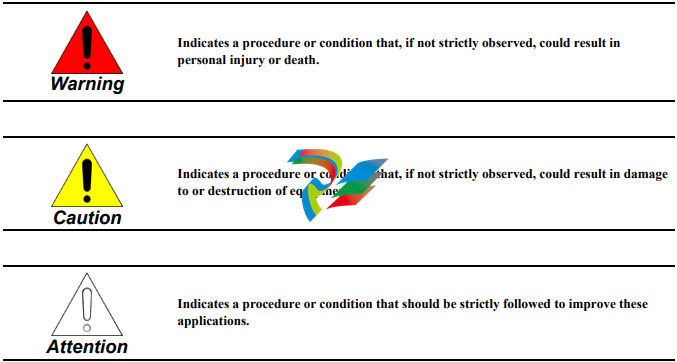
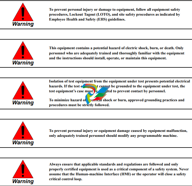
Control System Warnings
Control System Overview
Introduction
The Mark* VIe control system is a flexible platform used in multiple applications. Its architecture enables unique engineered solutions for a variety of large industrial applications. It features high-speed, networked input/output (I/O) for Simplex, Dual, and Triple Modular Redundant (TMR) systems. Industry-standard Ethernet communications are used for I/O, controllers, and supervisory interface to operator and maintenance stations, as well as third-party systems. The Mark VIeS Safety controller and I/O can operate independently or integrated with the rest of the Mark VIe controllers for safety-critical applications that conform to IEC® 61508. The ControlST* Software Suite, which contains the ToolboxST* application software, is used or programming, configuration, trending, and analyzing diagnostics for Mark controls and related systems. It provides quality, time-coherent data at controller and plant level for effectively managing control system equipment. ControlST simplifies maintenance while retaining a unique set of certified hardware and software blocks. ToolboxST provides a means to lock or unlock the Mark VIeS Safety controller for configuration and Safety Instrumented Function (SIF) programming The Universal I/O (UIO) control cabinet provides a platform for an independent, miniature version of the Mark VIe or Mark VIeS Safety control. The PUAA module is the standard Mark VIe compatible module, while the YUAA module is the companion module that is used in the Mark VIeS Safety control system. The UIO control cabinet is a lower cost, smaller footprint alternative to the standard Mark control cabinet. The control cabinet is installed at sites when there are I/O, power, and/or space limitations in the existing Mark VI, Mark VIe, or Mark VIeS control cabinet. This is especially required for upgrades when there are space restrictions. This unit may also be used as an independent Mark VIe or Mark VIeS control system, communicating directly with the Unit Data Highway (UDH) or Plant Data Highway (PDH), regardless of the existing controller at the site. The UIO control system supports specific I/O. For a list of supported I/O, refer to the Mark VIe and Mark VIeS Control Systems Volume II: System Guide for General-purpose Applications (GEH-6721_Vol_II). ToolboxST is used to set up, configure, and download to the UIO Mark VIe controller.
The information in this document applies to the overall Mark* VIe control system or Mark VIeS Functional Safety System control products; however, your application may not be licensed to access full system capability and I/O packs as described in this document. For example, the Mark VIeS Functional Safety System for General Markets only utilizes the following I/O packs:
• Analog I/O (YAIC)
• Universal Analog (YUAA)
• Vibration Input Monitor (YVIB)
• Relay Output (YDOA)
• Discrete Contact Input (YDIA)
• Power Distribution System Diagnostics (PPDA)
• Serial Modbus Communication (PSCA)
• Mark VIeS Safety Controller (UCSCS2x)
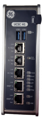
• Mark VIe Controller for Gateway (UCSCH1x)
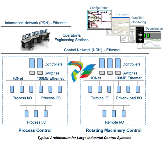
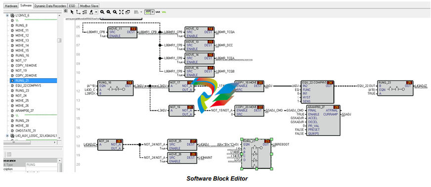
The Mark VIe and Mark VIeS control systems are used in a wide range of process control and protection applications, including steam, gas, and wind turbines, power generation balance of plant (BoP), deep sea drilling, desalinization, gas compression, and other facility-wide equipment management systems. The control system primarily consists of three hardware components: controller(s), I/O network (IONet) switches, and I/O modules. The control system provides more options for redundancy, better maintainability, and greater capability for locating I/O modules closer to the controlled equipment. It provides quality, time-coherent data at controller and plant level for effectively managing control system equipment. ControlST, which include the ToolboxST and WorkstationST applications, is used for programming, configuration, trending, and troubleshooting the Mark control product line. The following are two commonly used ToolboxST configuration screens.
Controllers
The Mark VIe controller is a stand-alone, single-board controller with scalable processing power. It includes built-in power supplies and requires no batteries or jumper settings. Controllers run the ControlST* Software Suite, providing a common software environment for turbine and generator excitation controls in the power island and balance of plant equipment to simplify operations and maintenance. The Mark VIeS Safety controller is IEC 61508 certified to SIL 3.
Controllers are loaded with software specific to its application, such as steam, gas, land-marine (LM), Balance of Plant (BoP), offshore drilling, desalination, CS, and Wind Power Conversion. It can run Relay Ladder Diagrams (RLD) or blocks. The IEEE® 1588 protocol is used through the R, S, and T I/O networks (IONet) to synchronize the clock of the I/O modules and controllers to within ±100 microseconds. Data is transferred to and from the control system database in the controller over the I/O networks (IONet). IONet data includes process inputs/outputs to the I/O packs.
In a dual system, IONet data also includes:
• Internal state values and initialization information from the designated controller • Status and synchronization information from both controllers In a triple module redundant (TMR) system, IONet data also includes: • Internal state values for voting and status and synchronization information from all three controllers • Initialization information from the designated controller
Note For more information on the Mark VIe controller, refer to the Mark VIe and Mark VIeS Control Systems Volume II: System Guide for General-purpose Applications (GEH-6721_Vol_II), the chapter Controllers. More more information on the Mark VIeS Safety controller, refer to the Mark VIeS Control Functional Safety Manual (GEH-6723). For a list of controllers that are available for each control system, including the supported and unsupported features the controllers offer for that control system, refer to the ToolboxST User Guide for Mark Controls Platform (GEH-6700 or GEH-6703).
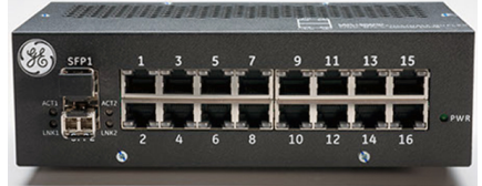
IONet Switches
GE’s Industrial Ethernet 10/100 switches (ESWA and ESWB) provide the performance and features needed in today’s real-time industrial control systems. Use 8-port ESWA or 16-port ESWB Ethernet switches in all control system I/O networks to maintain the reliability needed for I/O module reception of controller outputs.
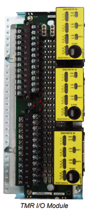
1.4 Distributed I/O Modules
The I/O modules contain three basic parts: terminal board, terminal block, and I/O pack. The terminal board mounts to the cabinet and comes in two basic types: S and T. The I/O pack mounts to the terminal board J-port connector. Both terminal board types provide the following features:
• Terminal blocks for I/O wiring
• Mounting hardware
• Input isolation and protection
• I/O pack connectors
• Unique electronic ID
I/O packs have a common processor board and a data acquisition board that is unique to the type of connected device. I/O packs on each terminal board digitize the I/O variables, perform algorithms, and communicate with the controller. The I/O pack provides fault detection through a combination of special circuitry in the data acquisition board and software running in the Central Processing Unit (CPU) board. The fault status is transmitted to and used by the controllers. The I/O pack transmits inputs and receives outputs on both network interfaces if connected.
Each I/O pack also sends an identification message (ID packet) to the main controller when requested. The packet contains, the hardware catalog number of the I/O board, the hardware revision, the board barcode serial number, the firmware catalog number, and the firmware version. The I/O packs have a temperature sensor that is accurate to within ±2 °C (±3.6 °F). Every I/O pack temperature is available in the database and can be used to generate an alarm.
Terminal Boards
Signal flow begins with a sensor connected to a terminal block on a board. Wide and narrow terminal boards are arranged in vertical columns of high and low-level wiring. An example of a wide board is a board that contains magnetic relays with fused circuits for solenoid drivers. A shield strip is provided to the left of each terminal block. It can be connected to a metal base for immediate grounding or floated to allow individual ground wires from each board to be wired to a centralized, cabinet ground strip.
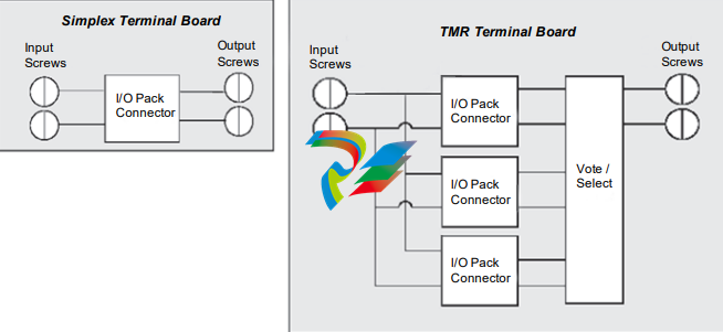
T-type
T-type terminal boards typically fan the sensor inputs to three separate I/O packs. Usually, the TMR board hardware votes the outputs from the three I/O packs. T-type boards contain two, 24-point, barrier-type, removable, terminal blocks. Each point can accept two 3.0 mm (0.12 in) (#12 AWG) wires with 300 V insulation per point with either spade or ring-type lugs. In addition, captive clamps are provided for terminating bare wires. Screw spacing is 9.53 mm (0.375 in) minimum and center-to-center
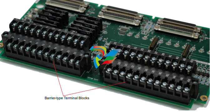
These terminal blocks have the following features:
• Black in color with white number labels
• Terminal rating is 300 V, 10 A
• UL recognized
• Recommended screw tightening torque is 7 lb-in (0.8 Nm)
S-type
S-type boards provide a single set of screws for each I/O point and allow a single I/O pack to condition and digitize the I/O. They are half the size of T-type boards and are standard base mounted but can also be DIN-rail mounted. These boards can be used for simplex, dual, or dedicated triple redundant sensors by using one, two, or three modules. S-type boards have Euro-style, box type terminal blocks. Some boards are available as either removable or fixed terminal block versions. S-type board terminal blocks accept one 2.05 mm (0.08 in) (#12 AWG) wire or two 1.63 mm (0.06 in) (#14 AWG) wires, each with 300 V insulation per point. Screw spacing is 5.08 mm (0.2 in) minimum and center-to-center.
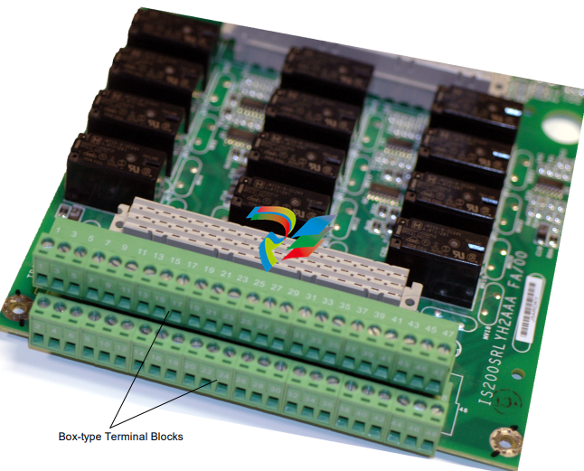
These terminal blocks have the following features:
• Green in color with number labels.
• Terminal rating is 300 V, 10 A
• UL and CSA recognized
• Recommended screw tightening torque is 5 lb-in (0.5 - 0.6 Nm
-
 OMRON 3G3XV-A2007 3G3XV-A2007-NEV2
 -
 Omron NJ1019000 NJ1 programable logic controller
 -
 OMRON C120-LK202-EV1/C120LK202EV1
 -
 OMRON C200H-AD003 PLC
 -
 OMRON C200H-CPU23-E COIL 24VDC PLC
 -
 Omron C200HG - C200H-ID212- C200H-OC226 C200HW-BC101 PLC Base Unit
 -
 OMRON C200H-OC222(Output Unit),C200H-PS211(Power Supply Unit),SP001 Module Rack
 -
 OMRON C200H-RT201 PROGRAMMABLE CONTROLLER
 -
 OMRON C200HS-CPU01-E SYSMAC PROGRAMMABLE CONTROLLER
 -
 OMRON C200H-SNT31 C200H Programmable Controllers
 -
 OMRON C200HW-MC402-E Motion control unit
 -
 OMRON C200PC-ISA02-DRM-E PLC ISA bus compatible board card
 -
 OMRON C500-CT012 PLC
 -
 OMRON C500-NC103-E PLC
 -
 OMRON C500-NC222-E PLC
 -
 OMRON C500-PRW05-V1 PLC
 -
 OMRON C500-PRW06 PROGRAMMABLE CONTROLLER
 -
 OMRON C500-PS223-E 3G2A5-PS223-E PLC SYSMAC PROGRAMMABLE CONTROLLER
 -
 OMRON C500-TU001 3G2A5-TU001 PLC PLC
 -
 OMRON C60H-C1DR-DE-V1 Programmable Controllers
 -
 OMRON C60H-C5DR-DE-V1 Programmable Controllers
 -
 OMRON C60H-C6DR-DE-V1 Programmable Controllers
 -
 OMRON CJ1G-CPU44H CPU module
 -
 OMRON CJ1G-CPU45H PLC
 -
 OMRON CJ1M-CPU13-ETN V4.0 PLC PLC
 -
 OMRON CJ1W-AD041-V1 Analog input uni
 -
 OMRON CJ1W-CORT21 PLC module
 -
 OMRON CJ1W-IDP01 Input unit
 -
 OMRON CJ1W-MCH71 - MECHATROLINK-II
 -
 OMRON CJ1W-MD261 Digital I/O
 -
 OMRON CJ1W-NC413 Position control unit
 -
 OMRON CJ1W-NCF71 Position Control Units
 -
 OMRON CJ1W-PTS51 Process Simulation I/O Module
 -
 OMRON CJ1W-PTS52 Process Simulation I/O Module
 -
 OMRON CJ1W-SCU21-V1 PLC
 -
 Omron CJ1W-SCU22 Serial Communication Unit
 -
 OMRON CJ1W-TC001 CJ Series Temperature Control Unit
 -
 Omron CK3W-AX1515N Motion Controller
 -
 Omron CP1E-N60DR-D Compact PLC CPU
 -
 OMRON CP1E-NA20DT1-D PLC PLC
 -
 OMRON CP1H-X40DT-D plc PLC
 -
 OMRON CPM2C-S110C-DRT Interface module
 -
 OMRON CQM1-AD041 PLC
 -
 SAACKE F‑GDSA‑1 / F‑GDSA‑2 Feuerungsautomaten
 -
 SAACKE F-GDSA 143303 Controller SHIPS UPS
 -
 ICS Triplex T8270 Trusted 24 Vdc FanAssembly
 -
 SCHNEIDER M522220000 SA SM_DO16R 16 DIGITAL OUTPUTS MODULE
 -
 LENZ EPL10200-W EPZ-10203 CANPT010W3E
 -
 OMRON CQM1H-ADB21 PLC
 -
OMRON CQM1H-CPU61 PLC
-
 OMRON CQM1H-MAB42 PLC
 -
 OMRON CQM1-TC102 CQM1-TC101 PLC
 -
 OMRON CS1G-CPU44-EV1 PLC
 -
 OMRON CS1G-CPU44H CPU
 -
OMRON CS1H-CPU63-EV1 PLC
-
 OMRON CS1H-CPU66-V1 PLC
 -
 OMRON CS1W-CLK13 PLC communication module
 -
OMRON CS1W-EIP21 PLC
-
 OMRON CS1W-MAD44 PLC PLC
 -
 OMRON CS1W-SCU31-V1 CVM1-BC103 PLC
 -
 Omron CVM1-CPU21-V2 CPU Unit
 -
 OMRON F150-C10E-2 Vision Controller
 -
 OMRON F150-C15E-3 Vision Controller
 -
 OMRON F160-C15E VISION MATE CONTROLLER
 -
 OMRON F500-C10-ETN F500-C15-ETN Vision Sensor
 -
 OMRON F500-VS F500-S1
 -
 OMRON FH-3050 FH Vision Controller
 -
 Omron FQ2-S25050F PLC Smart Camera
 -
 Omron FQM1-MMA22 Motion Module
 -
 OMRON GRT1-TS2P Temperature Module
 -
 OMRON H8PR-24 Cam Positioner
 -
 OMRON IDSC-C1DR-A-E Controller
 -
 OMRON K3HB-HTA-DRT1 Temperature Panel Meter
 -
 Omron KM-N1-FLK Power Detector
 -
 OMRON CJ1G-CPU43H CPU
 -
 OMRON NA5-7W001S-V1 NA5-9W001B-V1 NA5-12W101B-V1 Graphic panel
 -
 OMRON NA5-9W001B-V1 Graphic panel
 -
 OMRON NB10W-TW01B INTERACTIVE DISPLAY
 -
 OMRON NB7W-TW01B +CP1L-EL20DR-D Complete Power Panel
 -
 OMRON NB7W-TX01B INTERACTIVE DISPLAY PLC
 -
 Omron NE1A-SCPU02 Network Controller
 -
 OMRON NA5-7W001B-V1 NA5-7W001S-V1 NA5-9W001B-V1 NA5-12W101B-V1 touch screen
 -
 Omron NS5-SQ00B-V2 NS5-SQ00-V2 NS5-SQ01-V2 NS5-SQ01B-V2 touch display panel
 -
 Omron NJ301-1100 Programmable Logic Controller
 -
 OMRON NJ501-1300 CUP Unit Programmable Controller
 -
 Omron NS12-TS01B-V2 Interactive Display
 -
 OMRON NSJW-ETN21 ETHERNET HMI
 -
 OMRON NT10S-SF121 PLC
 -
 OMRON NT20S-ST121-EV3 Touch Screen
 -
 Omron NX1P2-1140DT-BA Programmable Controller
 -
 OMRON 3G3MV-P10CDT3-E RS422/485 INVERTER BOARD
 -
 Omron C500-ID219 3G2A5-ID219 System Microprocessor
 -
 Omron PLC B7AM-8B16
 -
 OMRON PLC Module CJ1W-AD081-V1
 -
 OMRON R88D-HS10 PLC
 -
OMRON R88D-HT10 plc
-
 OMRON R88D-KN01H-ML2 Servos G5-series
 -
 OMRON R88M-H10030-B plc
 -
 OMRON R88S-H306G plc PLC
 -
 Omron Relay G9SX-GS226-T15-RT
 -
 Omron S8AS-24006N S8AS Smart Power Supply FNIP
 -
 Omron Safety Input Unit NX-SIH400
 -
 OMRON SYSMAC SCY-P1 Sequential Controller
 -
OMRON SYSMAC SCY-P0 13E Sequential Controller
-
 OMRON NS8-TV00B-V2 NS8-TV00-V2 NS8-TV00B-ECV2 NS8-TV00-ECV2 touch display Panel
 -
 Omron V680-CA5D02-V2 Programmable Controller
 -
 OMRON SGDH-04AE-OY Servo Drive
 -
OMRON SGDH-10DE-OY Servo Drive
-
 OMRON SGDS-02A12A PLC + SGMAS-C2ACA21
 -
 OMRON SGMPH-04AAA61D-OY Servo Motor
 -
 Omron ZFV-CA40 Smart Sensor Amp Unit 24VDC 0.8A
 -
OMRON ZFV-NX1 CFP0260 ZFV-A20 VISION CONTROL PANEL
-
 OMRON ZFX-C15 SMART SENSOR AMP UNIT, Vision Sensor LCD
 -
 OMRON ZFX-C20/25-CD SMART SENSOR AMP UNIT, Vision Sensor LCD
 -
 OMRON-DIGITAL TEMPERATURE CONTROLLER E5AC-CX4A5M-014 r
 -
 ABB PFVL141V-2.0MN is an industrial-grade, rectangular roll force load cell
 -
 ABB PFVL141V-1.6MN is an industrial-grade, rectangular roll force load cell
 -
ABB PFVL141V-1.25MN high-performance, rectangular roll force load cell
-
 ABB PFVL141V-1.0MN high-precision, heavy-duty rectangular load cell
 -
 ABB PFVL141V-0.8MN high-precision, heavy-duty rectangular load cell
 -
 ABB PFVL141V-0.63MN high-precision, heavy-duty rectangular load cell
 -
 GE 151X1202YE08PP08 Panel of the case / Structural component
 -
 GE 151X1212HB01MG02 Integrated LCI Controller (Old Model)
 -
 GE 151X1212GC01PC02 LCI Static Startup Controller
 -
 GE 151X1235FD01PK01 High-speed Digital Input Interface Board
 -
 GE 151X1215DK01PC01 Signal Processing / Amplification Board
 -
 GE 151X1238WP99BK01 6-pulse LCI power conversion module
 -
 GE 151X1225DF01PC03RA - Power Conversion / Drive Regulation Board


