
HIMAHIMatrix Safety-Related Controller F31 03 Manual
For connecting a load to a 1-pole switching output, use the corresponding L- ground of
the respective channel group (2-pole connection) to ensure that the internal protective
circuit can function.
nductive loads may be connected with no free-wheeling diode on the actuator. However, HIMA
strongly recommends connecting a protective diode directly to the actuator.
Reaction in the Event of a Fault
If the device detects a faulty signal on a digital output, the affected module output is set to the
safe (de-energized) state using the safety switches.
If a device fault occurs, all digital outputs are switched off.
In both cases, the devices activates the FAULT LED.
The error code allows the user to configure additional fault reactions in the user program.
information on how to install, start up and configure the module in SILworX.
1.1 Structure and Use of this Manual
The content of this manual is part of the hardware description of the HIMatrix programmable
electronic system.
This manual is organized in the following main chapters:
Introduction
Safety
Product Description
Start-up
Operation
Maintenance
Decommissioning
Transport
Disposal
Additionally, the following documents must be taken into account:
Name Content Document number
HIMatrix System Manual
Compact Systems
Hardware description of the HIMatrix
compact systems
HI 800 141 E
HIMatrix Safety Manual Safety functions of the HIMatrix system HI 800 023 E
HIMatrix Safety Manual for
Railway Applications
Safety functions of the HIMatrix system
using the HIMatrix in railway
applications
HI 800 437 E
SILworX Communication
Manual
Description of the communication
protocols, ComUserTask and their
configuration in SILworX
HI 801 101 E
SILworX Online Help Instructions on how to use SILworX -
SILworX First Steps Introduction to SILworX using the
HIMax system as an example
HI 801 103 E
Table 1: Additional Relevant Documents
The latest manuals can be downloaded from the HIMA website at www.hima.com. The revision
index on the footer can be used to compare the current version of existing manuals with the
Internet edition.
1.2 Target Audience
This document addresses system planners, configuration engineers, programmers of
automation devices and personnel authorized to implement, operate and maintain the modules
and systems. Specialized knowledge of safety-related automation systems is required
1.3 Formatting Conventions
To ensure improved readability and comprehensibility, the following fonts are used in this
document:
Bold To highlight important parts.
Names of buttons, menu functions and tabs that can be clicked and used
in the programming tool.
Italics For parameters and system variables
Courier Literal user inputs
RUN Operating state are designated by capitals
Chapter 1.2.3 Cross references are hyperlinks even though they are not particularly
marked. When the cursor hovers over a hyperlink, it changes its shape.
Click the hyperlink to jump to the corresponding position.
Safety notes and operating tips are particularly marked.
1.3.1 Safety Notes
The safety notes are represented as described below.
These notes must absolutely be observed to reduce the risk to a minimum. The content is
structured as follows:
Signal word: warning, caution, notice
Type and source of risk
Consequences arising from non-observance
Risk prevention
Type and source of risk!
Consequences arising from non-observance
Risk prevention
The signal words have the following meanings:
Warning indicates hazardous situation which, if not avoided, could result in death or serious
injury.
Caution indicates hazardous situation which, if not avoided, could result in minor or modest
injury.
Notice indicates a hazardous situation which, if not avoided, could result in property damage
Type and source of damage!
Damage prevention
Safety
All safety information, notes and instructions specified in this document must be strictly
observed. The product may only be used if all guidelines and safety instructions are adhered to.
This product is operated with SELV or PELV. No imminent risk results from the product itself.
The use in Ex-Zone is permitted if additional measures are taken.
2.1 Intended Use
HIMatrix components are designed for assembling safety-related controller systems.
When using the components in the HIMatrix system, comply with the following general
requirements.
Environmental Requirements
Requirement type Range of values
Protection class Protection class III in accordance with IEC/EN 61131-2
Ambient temperature 0...+60 °C
Storage temperature -40...+85 °C
Pollution Pollution degree II in accordance with IEC/EN 61131-2
Altitude < 2000 m
Housing Standard: IP20
Supply voltage 24 VDC
Table 2: Environmental Requirements
Exposing the HIMatrix system to environmental conditions other than those specified in this
manual can cause the HIMatrix system to malfunction.
2.1.2 ESD Protective Measures
Only personnel with knowledge of ESD protective measures may modify or extend the system
or replace devices.
Device damage due to electrostatic discharge!
When performing the work, make sure that the workspace is free of static, and wear
an ESD wrist strap.
If not used, ensure that the device is protected from electrostatic discharge, e.g., by
storing it in its packaging
Residual Risk
No imminent risk results from a HIMatrix system itself.
Residual risk may result from:
Faults related to engineering
Faults related to the user program
Faults related to the wiring
2.3 Safety Precautions
Observe all local safety requirements and use the protective equipment required on site.
2.4 Emergency Information
A HIMatrix system is a part of the safety equipment of a site. If a device or a module fails, the
system enters the safe state.
In case of emergency, no action that may prevent the HIMatrix systems from operating safely is
permitted.
Product Description
The safety-related F31 03 controller is a compact system in a metal housing with 20 digital
inputs and 8 digital outputs.
The configuration is performed using SILworX, see Chapter 4.3.
The device is suitable for sequence of events recording (SOE), see Chapter 4.2. The device
supports multitasking and reload. For more details, refer to the system manual compact
systems (HI 800 141 E).
The device is TÜV-certified for safety-related applications up to SIL 3 (IEC 61508, IEC 61511
and IEC 62061), Cat. 4 and PL e (EN ISO 13849-1) and SIL 4 (EN 50126, EN 50128 and
EN 50129).
Further safety standards, application standards and test standards are specified in the
certificates available on the HIMA website.
Safety Function
The controller is equipped with safety-related digital inputs and outputs.
3.1.1 Safety-Related Digital Inputs
The controller is equipped with 20 digital inputs. The state (HIGH, LOW) of each input is
signaled by an individual LED.
Mechanical contacts without own power supply or signal power source can be connected to the
inputs.
Potential-free mechanical contacts without own power supply are fed via an internal shortcircuit-proof 24 V power source (LS+). Each of them supply a group of 4 mechanical contacts.
Figure 1 shows how the connection is performed.
With signal voltage sources, the corresponding ground must be connected to the input (L-), see
Figure 1.
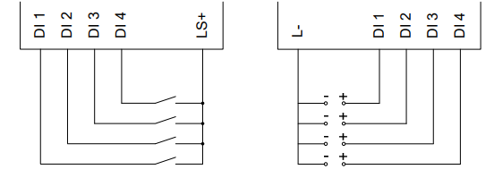
For the external wiring and the connection of sensors, apply the de-energized-to-trip principle.
Thus, if a fault occurs, the input signals adopt a de-energized, safe state (low level).
If an external wire is not monitored, an open-circuit is considered as safe low level.
Reaction in the Event of a Fault
If the device detects a fault on a digital input, the user program processes a low level in
accordance with the de-energized to trip principle.
The device activates the FAULT LED.
In addition to the channel signal value, the user program must also consider the corresponding
error code.
The error code allows the user to configure additional fault reactions in the user program.
Line Control
Line control is used to detect short-circuits or open-circuits and can be configured for the F31
system, e.g., on EMERGENCY STOP inputs complying with Cat. 4 and PL e in accordance with
EN ISO 13849-1.
To this end, connect the digital outputs DO 1 through DO 8 of the system to the digital inputs DI
of the same system as follows:
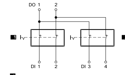
The controller pulses the digital outputs to detect the line short-circuits and open-circuits on the
lines connected to the digital inputs. To do so, configure the Value [BOOL] -> system variable in
SILworX. The variables for the pulsed outputs must begin with channel 1 and reside in direct
sequence, one after the other.
If the following faults occur, the FAULT LED located on the front plate of the controller blinks,
the inputs are set to low level and an (evaluable) error code is created:
Cross-circuit between two parallel wires.
Invalid connections of two lines (e.g., DO 2 to DI 3),
Earth fault on one wire (with earthed ground only).
Open-circuit or open contacts, i.e., including when one of the two EMERGENCY STOP
switches mentioned above has been engaged, the FAULT LED blinks and the error code is
created.
Safety-Related Digital Outputs
The controller is equipped with 8 digital outputs. The state (HIGH, LOW) of each output is
signaled by an individual LED (HIGH, LOW).
At the maximum ambient temperature, the outputs 1...3 and 5...7 can be loaded with 0.5 A
each; and outputs 4 and 8 can be loaded with 1 A or with 2 A at an ambient temperature of up
to 50 °C.
If an overload occurs, one or all digital outputs are switched off. If the overload is removed, the
outputs are switched on again automatically, see Table 14.
The external wire of an output is not monitored, however, a detected short-circuit is signaled.
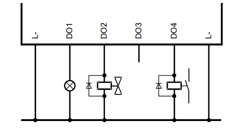
The redundant connection of two outputs must be decoupled with diodes
Equipment, Scope of Delivery
The following table specifies the available controller:
Designation Description
F31 03
SILworX
Controller (enhanced performance, 20 digital inputs, 8 digital outputs),
Operating temperature: 0...+60 °C,
for SILworX programming tool
IP Address and System ID (SRS)
A transparent label is delivered with the device to allow one to note the IP addresses of the CPU
and the COM and the system ID (SRS for system rack slot) after a change.
Default value for IP address of the CPU: 192.168.0.99
Default value for IP address of the COM: 192.168.0.100
Default value for SRS: 60 000.0.0
The label must be affixed such that the ventilation slots in the housing are not obstructed.
Refer to the SILworX First Steps manual for more information on how to modify the IP address
and the system ID.
Type Label
The type plate contains the following details:
Product name
Bar code (1D or 2D code)
Part no.
Production year
Hardware revision index (HW Rev.)
Firmware revision index (FW Rev.)
Operating voltage
Mark of conformity
Structure
This chapter describes the layout and function of the controller, and its connection for
communication
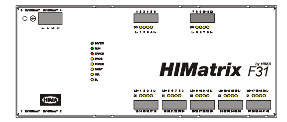
LED Indicators
The light-emitting diodes (LEDs) indicate the operating state of the controller. The LEDs are
classified as follows:
Operating voltage LED
System LEDs
Communication LED
I/O LEDs
When the supply voltage is switched on, a LED test is performed and all LEDs are briefly lit.
Definition of Blinking Frequencies
The following table defines the blinking frequencies of the LEDs:
Name Blinking frequencies
Blinking1 Long (approx. 600 ms) on, long (approx. 600 ms) off
Blinking-x Ethernet communication: Blinking synchronously with data transfer
Communication LEDs
All RJ-45 connectors are provided with a small green and a yellow LEDs. The LEDs signal the
following states:
LED Status Description
On Full duplex operation
Blinking1 IP address conflict, all communication LEDs are blinking
Blinking-x Collision
Green
Off Half duplex operation, no collision
On Connection available
Blinking1 IP address conflict, all communication LEDs are blinking
Blinking-x Interface activity
Yellow
Off No connection available
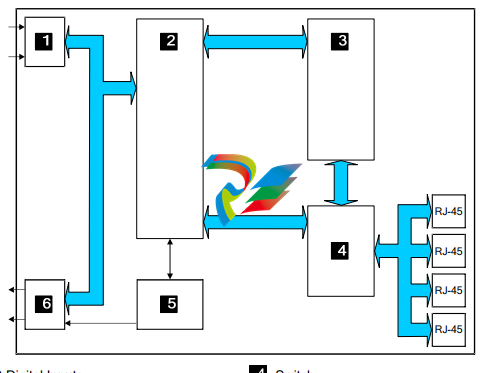
Communication
The controller communicates with remote I/Os via safeethernet. Characteristics and
configuration of safeethernet are described in the SILworX communication manual
(HI 801 101 E).
3.4.2.1 Connections for Ethernet Communication
Property Description
Port 4 x RJ-45
Transfer standard 10BASE-T/100BASE-Tx, half and full duplex
Auto negotiation Yes
Auto crossover Yes
IP address Freely configurable1)
Subnet mask Freely configurable1)
Supported protocols Safety-related: safeethernet, PROFIsafe
Standard protocols: Programming and debugging tool (PADT),
OPC, Modbus TCP, TCP SR, SNTP, ComUserTask,
PROFINET
1) The general rules for assigning IP address and subnet masks must be adhered to.
Table 9: Ethernet Interfaces Properties
Two RJ-45 connectors with integrated LEDs are located on the top and on the bottom left-hand
side of the housing. Refer to Chapter 3.4.1.3 for a description of the LEDs' function.
The connection parameters are read based on the MAC address (media access control
address) defined during manufacturing.
CPU and COM have their own MAC addresses. The CPU MAC address is specified on a label
located above the two RJ-45 connectors (1 and 2).
Figure 7: Sample MAC Address Label
The COM MAC address corresponds to the CPU MAC address, except for the last byte which is
increased by 1.
Example:
CPU MAC address: 00:E0:A1:00:06:C0
COM MAC address: 00:E0:A1:00:06:C1
The controller is equipped with an integrated switch for Ethernet communication. For further
information on the integrated switch and safeethernet, refer to Chapter Communication of the
system manual for compact systems (HI 800 141 E).
Network Ports Used for Ethernet Communication
UDP ports Use
123 SNTP (time synchronization between PES and remote I/O, PES and
external devices)
502 Modbus salve (can be modified by the user)
6010 safeethernet and OPC
6005 / 6012 If TCS_DIRECT was not selected in the HH network
8000 Programming and operation with SILworX
8004 Configuration of the remote I/O using the PES (SILworX)
34 964 PROFINET endpoint mapper (required for establishing the connection)
49 152 PROFINET RPC server
49 153 PROFINET RPC client
Table 10: Network Ports (UDP Ports) in Use
TCP ports Use
502 Modbus salve (can be modified by the user)
xxx TCP SR assigned by the user
Table 11: Network Ports (TCP Ports) in Use
i The ComUserTask can use any port if it is not already used by another protocol.
Reset Key
The controller is equipped with a reset key. The key is only required if the user name or
password for administrator access is not known. If only the IP address set for the controller does
not match the PADT (PC), the connection can be established with a Route add entry on the
PC.
The key can be accessed through a small round hole located approximately 5 cm from the
upper left-hand side of the housing. The key is engaged using a suitable pin made of insulating
material to avoid short-circuits within the controller.
The reset is only effective if the controller is rebooted (switched off and on) while the key is
simultaneously engaged for at least 20 s. Engaging the key during operation has no effect.
Properties and behavior of the controller after a reboot with engaged reset key:
Connection parameters (IP address and system ID) are set to the default values.
All accounts are deactivated except for the administrator default account with empty
password.
Loading a user program or operating system with default connection parameters is inhibited!
The loading procedure is only allowed after the connection parameters and the account have
been configured on the controller and the controller has been rebooted.
After a new reboot without the reset key engaged, the connection parameters (IP address and
system ID) and accounts become effective.
Those configured by the user.
Those valid prior to rebooting with the reset key engaged, if no changes were performed.
3.4.4 Hardware Clock
In case of loss of operating voltage, the power provided by an integrated capacitor is sufficient
to buffer the hardware clock for approximately one week.
Start-up
To start up the controller, it must be mounted, connected and configured in SILworX.
4.1 Installation and Mounting
The controller is mounted on a 35 mm DIN rail such as described in the system manual for
compact systems.
When laying cables (long cables, in particular), take appropriate measures to avoid interference,
e.g., by separating the signal lines from the power lines.
When dimensioning the cables, ensure that their electrical properties have no negative impact
on the measuring circuit.
4.1.1 Connecting the Digital Inputs
Use the following terminals to connect the digital inputs:
Surges on Digital Inputs
Due to the short cycle time of the HIMatrix systems, a surge pulse as described in
EN 61000-4-5 can be read in to the digital inputs as a short-term high level.
The following measures ensure proper operation in environments where surges may occur:
1. Install shielded input wires
2. Program noise blanking in the user program. A signal must be present for at least two cycles
before it is evaluated. The fault reaction is triggered with a corresponding delay.
i The measures specified above are not necessary if the plant design precludes surges from
occurring within the system.
In particular, the design must include protective measures with respect to overvoltage,
lightning, earth grounding and plant wiring in accordance with the relevant standards and the
instructions specified in the system manual (HI 800 141 E or HI 800 191 E).
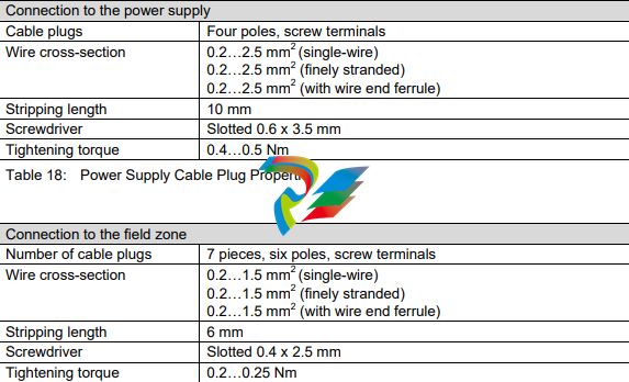
Cable Plugs
Cable plugs attached to the pin headers of the devices are used to connect to the power supply
and to the field zone. The cable plugs are included within the scope of delivery of the HIMatrix
devices and modules.
The devices power supply connections feature the following properties:
Sequence of Events Recording (SOE)
The global variables of the controller can be monitored using sequence of events recording.
Global variables to be monitored are configured using SILworX, see the online help and the
SILworX communication manual (HI 801 101 E). Up to 4000 events can be configured.
An event is composed of:
-
 Beckhoff PLC module CX1020-0000 Basic CPU module (service phase)
 -
 Beckhoff CP7812-1056-0010 15" Multitouch Display Control Panel
 -
 Beckhoff CX5120-0115 /2GB Controller Module
 -
 Beckhoff CP7201-1000-0000 Industrial Panel PC
 -
 Beckhoff Servo Motor AM8061-0JH1-0000
 -
 BECKHOFF CP6503-0001-0050 Built-in Panel PC
 -
 Beckhoff CP3919-0010 Display G190ETN01.2 19" PCT V04. Multi-touch Control Panel
 -
 Beckhoff CX5110-0112-9020/000368201 Embedded PC Intel Atom Processor
 -
 Beckhoff AX8206-0000 Dual-Axis Module
 -
Beckhoff Nail Operating Terminal CP7032-1031-0010
-
Beckhoff AM8042-0EH1-0000 Servomotor 4.10 Nm (M0), F4 (87 mm)
-
 Beckhoff EK9300 Beckhoff CPU Module
 -
Beckhoff CP3224-0020 Multitouch-Panel-PC
-
 Beckhoff CP2712-0000 12.1" 24VDC Touch Screen WMD0
 -
 BECKHOFF CX5240-0195 / 0000289234 Embedded PC 40 GB CFast Card
 -
 Beckhoff CP6932-1000-0000 Control Panel
 -
 BECKHOFF CX5120-0121 PLC Module
 -
 Beckhoff EL3218 | EtherCAT Terminal, 8-channel analog input
 -
 Beckhoff C6640-0050 | Control cabinet Industrial PC
 -
 Beckhoff Cx5130-0120/4GB Embedded-PC
 -
 BECKHOFF CX2030-0122 PLC PROCESSOR
 -
 BECKHOFF CX5020-0122 Controller Module
 -
 Beckhoff CP3915-0000 Multitouch Panel
 -
 BECKHOFF EL3014 | EtherCAT Terminal
 -
 BECKHOFF Industrial Computer c6920-1057-0030
 -
 Beckhoff CX5130-0141/4GB CX5130-0141 Embedded PC
 -
 Beckhoff C6240-1052-0040 4-086-06-3073 Industrial Computer
 -
 Beckhoff CX5140-0135 /4GB High-Performance Embedded Industrial PC
 -
 Beckhoff C6515-1001-0000 Industrial PC
 -
 Beckhoff AX5103-0000-0200 - Digital Compact Servo Drives
 -
 Beckhoff CX2030-0130-1003/4GB Basic CPU module
 -
 Beckhoff AX8620-0000 Power Supply Module
 -
 Beckhoff CX9020-0111 module with
 -
 Beckhoff EL7332 PLC Module
 -
 BECKHOFF CP7709-0001-0020 HMI
 -
 Beckhoff CX5120-0155/2GB Embedded PC
 -
 BECKHOFF CP7037-1037-0010 OPERATOR INTERFACE TOUCHSCREEN
 -
 Beckhoff EK9000 | ModbusTCP/UDP Bus Coupler
 -
 Beckhoff Touch Panel Screen CP6020 -0000-0000
 -
 Beckhoff CX2020-0121 Module FAST Shipping
 -
 Beckhoff CX2030-0125 Basic CPU Module
 -
 Beckhoff CP3918-0000 Multi-Touch 18.5" Control Panel
 -
 Automotion LC4A00010 DC BL Motor Control, ATS, Sub Assy, SCP, 115VAC,
 -
 500T-115VAC - VAS ENGINEERING - DORIC 500 SERIES DIGITAL TEMP INDICATOR
 -
 Honeywell X-DCS2000/EN Digital Integrated System Manager 50/60Hz 100-240V #4
 -
 Kollmorgen S60600 Servostar600 606-Fan 4 kVA, 6 A, 3 X 230 - 480 V
 -
 ABB XZ C828 A101 Didt Dioder Snubber 3BHE039453R0101
 -
 ABB 3BHB027232R0001 1-Phase Charging Transformer
 -
 ABB 3BHE006412R0101 Circuit Board UFC762AE101
 -
 ABB XVC770BE101 3BHE021083R0101 Circuit Board
 -
 ABB 3BHE021887R0101 (Model: UBCC717BE101 / UBC717BE101) is an advanced
 -
 ABB 3BHE032593R0001 Isolated Power Supply
 -
 ABB 3BSC610023R0001 POWER SUPPLY SD812
 -
 Beckhoff C6650-0060 | Control cabinet Industrial PC
 -
 Beckhoff CP2916-0000 Industrial HMI Display Panel
 -
 Beckhoff AM8053-0L2B-0000 Servomotor 15.4 Nm (M0), F5 (104 mm)
 -
 Beckhoff CP6202-0001-0020 Industrial Panel PC
 -
Beckhoff CX2020-0120 Plc Module
-
 Beckhoff CX1010-0111 BASIC CPU MODULE
 -
 Beckhoff C6017-0010 | Ultra-compact Industrial PC
 -
 BECKHOFF CX2040-0155 Plc Module
 -
 Beckhoff CX5120-0125 Embedded PC
 -
 BECKHOFF C6930-0040 INDUSTRIAL CONTROL COMPUTER
 -
 Beckhoff CP6907-0001-0000 Economy Built-in Control Panel
 -
 Beckhoff CP2912-0000 Multi-Touch Built-In Control Panel
 -
 Beckhoff C6015-0010 Ultra-Compact Industrial PC
 -
 Beckhoff CX5130 | Embedded PC with Intel Atom® E3827
 -
 Beckhoff C6030-0060 Ultra-Compact Industrial PC
 -
 OMRON 3G3XV-A2007 3G3XV-A2007-NEV2
 -
 Omron NJ1019000 NJ1 programable logic controller
 -
 OMRON C120-LK202-EV1/C120LK202EV1
 -
 OMRON C200H-AD003 PLC
 -
 OMRON C200H-CPU23-E COIL 24VDC PLC
 -
 Omron C200HG - C200H-ID212- C200H-OC226 C200HW-BC101 PLC Base Unit
 -
 OMRON C200H-OC222(Output Unit),C200H-PS211(Power Supply Unit),SP001 Module Rack
 -
 OMRON C200H-RT201 PROGRAMMABLE CONTROLLER
 -
 OMRON C200HS-CPU01-E SYSMAC PROGRAMMABLE CONTROLLER
 -
 OMRON C200H-SNT31 C200H Programmable Controllers
 -
 OMRON C200HW-MC402-E Motion control unit
 -
 OMRON C200PC-ISA02-DRM-E PLC ISA bus compatible board card
 -
 OMRON C500-CT012 PLC
 -
 OMRON C500-NC103-E PLC
 -
 OMRON C500-NC222-E PLC
 -
 OMRON C500-PRW05-V1 PLC
 -
 OMRON C500-PRW06 PROGRAMMABLE CONTROLLER
 -
 OMRON C500-PS223-E 3G2A5-PS223-E PLC SYSMAC PROGRAMMABLE CONTROLLER
 -
 OMRON C500-TU001 3G2A5-TU001 PLC PLC
 -
 OMRON C60H-C1DR-DE-V1 Programmable Controllers
 -
 OMRON C60H-C5DR-DE-V1 Programmable Controllers
 -
 OMRON C60H-C6DR-DE-V1 Programmable Controllers
 -
 OMRON CJ1G-CPU44H CPU module
 -
 OMRON CJ1G-CPU45H PLC
 -
 OMRON CJ1M-CPU13-ETN V4.0 PLC PLC
 -
 OMRON CJ1W-AD041-V1 Analog input uni
 -
 OMRON CJ1W-CORT21 PLC module
 -
 OMRON CJ1W-IDP01 Input unit
 -
 OMRON CJ1W-MCH71 - MECHATROLINK-II
 -
 OMRON CJ1W-MD261 Digital I/O
 -
 OMRON CJ1W-NC413 Position control unit
 -
 OMRON CJ1W-NCF71 Position Control Units
 -
 OMRON CJ1W-PTS51 Process Simulation I/O Module
 -
 OMRON CJ1W-PTS52 Process Simulation I/O Module
 -
 OMRON CJ1W-SCU21-V1 PLC
 -
 Omron CJ1W-SCU22 Serial Communication Unit
 -
 OMRON CJ1W-TC001 CJ Series Temperature Control Unit
 -
 Omron CK3W-AX1515N Motion Controller
 -
 Omron CP1E-N60DR-D Compact PLC CPU
 -
 OMRON CP1E-NA20DT1-D PLC PLC
 -
 OMRON CP1H-X40DT-D plc PLC
 -
 OMRON CPM2C-S110C-DRT Interface module
 -
 OMRON CQM1-AD041 PLC
 -
 SAACKE F‑GDSA‑1 / F‑GDSA‑2 Feuerungsautomaten
 -
 SAACKE F-GDSA 143303 Controller SHIPS UPS
 -
 ICS Triplex T8270 Trusted 24 Vdc FanAssembly
 -
 SCHNEIDER M522220000 SA SM_DO16R 16 DIGITAL OUTPUTS MODULE
 -
 LENZ EPL10200-W EPZ-10203 CANPT010W3E
 -
 OMRON CQM1H-ADB21 PLC
 -
OMRON CQM1H-CPU61 PLC
-
 OMRON CQM1H-MAB42 PLC
 -
 OMRON CQM1-TC102 CQM1-TC101 PLC
 -
 OMRON CS1G-CPU44-EV1 PLC
 -
 OMRON CS1G-CPU44H CPU
 -
OMRON CS1H-CPU63-EV1 PLC
-
 OMRON CS1H-CPU66-V1 PLC
 -
 OMRON CS1W-CLK13 PLC communication module
 -
OMRON CS1W-EIP21 PLC
-
 OMRON CS1W-MAD44 PLC PLC
 -
 OMRON CS1W-SCU31-V1 CVM1-BC103 PLC


