
FOXBORO Z-Module Control Processor 270 (ZCP270)
FOXBORO Z-Module Control Processor 270 (ZCP270)
Z-Module Control Processor 270 (ZCP270)
The Z-Module Control Processor 270 is a distributed, optionally fault-tolerant controller that performs
process control and alarming functions according to a user-defined control strategy.
FEATURES

Performs regulatory, logic, timing, and sequential
control together with connected Fieldbus
Modules
Supports up to 128 of the 200 Series Fieldbus
Modules (FBMs - Compact or standard types)
when using the FCM100Et Fieldbus
Communications Module
Supports up to 128 of the 200 Series FBMs
(Compact or standard types), 100 Series FBMs,
or a combination 100 Series and 200 Series
FBMs when using the FCM100E Fieldbus
Communications Module
Performs data acquisition and alarm detection
and notification
Offers unique, patented, fault-tolerant operation
using two control modules to greatly improve
reliability relative to other process controllers
Connects to The MESH control network via
standard fiber optic 100 Mbps Ethernet
Uses versatile control algorithms and a wide
variety of FBMs to provide control capabilities for
a broad range of process applications
Supports time synchronization using optional
external time from GPS satellites
Offers on-line image update of a fault-tolerant
ZCP270 without shutting down the process
Uses soft letterbugs configurable via the
I/A Series® system Letterbug Configurator.
Supports self-hosting mode with I/A Series
software v8.4-v8.8 or Foxboro Evo™ Control
Core Services v9.0 or later
OVERVIEW
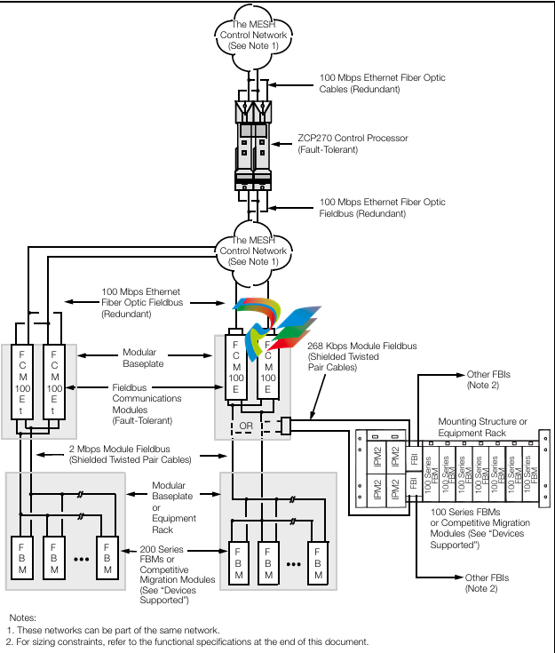
The Z-Module Control Processor 270 (ZCP270) is an
optionally fault-tolerant, Z-form factor controller. The
ZCP270 performs regulatory, logic, timing, and
sequential control together with connected Fieldbus
Communications Modules (FCMs) and Fieldbus
Modules. It also performs data acquisition and alarm
detection and notification. The ZCP270 connects to
The MESH control network and
FCM100Ets/FCM100Es via standard fiber optic 100
Mbps Ethernet. The FCM100Et interfaces the
2 Mbps Module Fieldbus used by the 200 Series
FBMs and the FCM100E interfaces the 2 Mbps
Module Fieldbus used by the 200 Series FBMs or the
268 Kbps Fieldbus used by 100 Series FBMs.
Depending on sizing considerations, the ZCP270 can
be used with a mix of FCM100E and FCM100Et
modules.
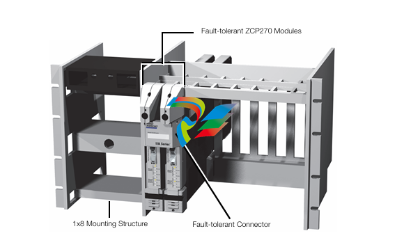
The fault-tolerant version of the ZCP270 consists of
two single-width processor modules. These modules
install in adjacent ZCP270 slots in a 1x8 or 2x8
mounting structure and connect to a fault-tolerant
connector to allow for high-speed communication
between the modules (see Figure 1).
EQUIPMENT MOUNTING
The Foxboro Evo architecture requires workstations
and commercial-off-the-shelf (COTS) Ethernet
switches, a rack room for the ZCP270 and Ethernet
switches, and a field enclosure for the
FCM100Ets/FCM100Es, FBMs, and other I/O
hardware. For more information on The MESH
control network architecture, refer to
PSS 21H-7C2 B3.
ENHANCED RELIABILITY (FAULT
TOLERANCE)
The unique and patented fault-tolerant operation of
the ZCP270 greatly improves reliability relative to
other process controllers. The fault-tolerant version of
the ZCP270 consists of two modules operating in
parallel, with two sets of Ethernet connections to The
MESH network, two for the control network and two
for the fieldbus network. The two ZCP270 modules,
married together as a fault-tolerant pair, provide
continuous operation of the controller in the event of
virtually any hardware failure occurring within one
module of the pair.
Both modules receive and process information
simultaneously, and faults are detected by the
modules themselves. One of the significant methods
of fault detection is comparison of communication
messages at the module external interfaces.
Messages only leave the controller when both
controllers agree on the message being sent (bit for
bit match). Upon detection of a fault, self-diagnostics
are run by both modules to determine which module
is defective. The non-defective module then assumes
control without affecting normal system operations.
This fault-tolerant solution has the following major
advantages over controllers that are merely
redundant:

No bad messages are sent to the field or to
applications using controller data because no
message is allowed out of the controller unless
both modules match bit for bit on the message
being sent.
The secondary controller is synchronized with the
primary one, which ensures up to the moment
data in the event of a primary controller failure.
The secondary controller will have latent flaws
detected prior to any switchover because it is
performing exactly the same operations as the
primary controller.
SPLITTER/COMBINER
Fault-tolerant ZCP270 modules connect to two pair
of fiber optic splitter/combiners (see Figure 1). One
splitter/combiner pair connects redundant Ethernet
ports on the front of each module to redundant
Ethernet switches in the control network. The other
splitter/combiner pair connects redundant Ethernet
fieldbus ports on the top of each module to
redundant Ethernet switches in the control network.
For each module, the splitter/combiners provide
separate transmit/receive fiber connections for each
Ethernet control network and Ethernet fieldbus port.
Fiber cables are connected so that splitter/combiners
pass inbound traffic from a switch to both modules,
and pass outbound traffic from the primary module
to a switch.
Each splitter/combiner pair mounts in an assembly
that either mounts in a chassis assembly for 19-inch
racks or fastens to the DIN rail in the enclosure. The
splitter/combiner is a passive device that does not
require electrical power.
ENHANCED COMMUNICATIONS
The Foxboro Evo architecture uses an Ethernet
control network with 100 Mbps data
communications between the ZCP270s and the
Ethernet switches (see Figure 2).
The ZCP270 can also communicate with serial and
Ethernet devices, such as PLCs, via Field Device
System Integrators and FCM100Ets/FCM100Es. This
allows connection to new device interfaces without
any changes to the controller software.
ON-LINE IMAGE UPDATE
For fault-tolerant ZCP270 modules, on-line image
update replaces the executable image (operating
system) of a running ZCP270 with a newer image
without having to shut down the equipment being
controlled by the ZCP270. New product
enhancements can be brought on-line in
1.5 seconds for heavily loaded controllers; less for
lightly loaded controllers.
Because the ZCP270 contains its executable image
in internal flash memory, and has sufficient RAM to
hold a new executable image at the same time, on
line image updates are now much easier to perform.
TIME SYNCHRONIZATION, SOE, TDRA
The Foxboro Evo system supports time
synchronization using either an externally maintained
optional source of Universal Coordinated Time (UTC)
from GPS satellites or an internal source using
proprietary software. ZCP270s and their FCM100Ets
receiving time updates via the external time source
synchronize their FBMs to 1 ms. For more
information, refer to PSS 21S-1C2 B3.
Time stamping is used for alarm messages, values
sent to the historian, and the new Sequence Of
Events (SOE) and Transient Data Recorder and
Analyzer (TDRA) features.
SOE data are discrete points that are time stamped
at the FBM, optionally to 1 ms, and sent to the
workstation on a change basis. TDRA data are
analog points that are time stamped at the FBM and
sent to the workstation every 10 ms. These new
features are supported by client software in the
workstation. To support SOE and TDRA, the
FCM100Et must be installed on the same network as
the workstation collecting the data. For information
on this software, refer to PSS 21S-2B9 B4 and
PSS 21S-2B10 B4
SOFTWARE FEATURES
The ZCP270 performs regulatory, logic, timing, and
sequential control, as well as data acquisition, alarm
detection, and alarm notification. Process variables
are controlled using time-proven algorithms
(mathematical computations performing specific
functions). The algorithms are contained in functional
control blocks, which are configured by on-site
process engineers to implement the desired control
strategies. The versatility of the algorithms, coupled
with the variety of FBMs available, provides control
capabilities suited to a broad range of process
applications. Control strategies ranging from simple
feedback and cascade loops to highly sophisticated
feedforward, nonlinear, and complex characterization
control schemes are readily implemented.
The ZCP270 also provides the following features:
Infrared communications with the controller
enables you to set and read the controller
letterbug via the Letterbug Configurator.
Alarm enhancements to the function blocks:
re-alarming on changes to alarm priority,
re-alarming based upon a configurable time delay
deadband, and alarm suppression based upon
time.
Optional UTC external time synchronization.
Improved controller performance.
Optional self-hosting mode (I/A Series software
v8.4-v8.8 or Control Core Services v9.0 or later)
allows the ZCP270 to start up and run, executing
its configured control scheme using the
checkpoint file stored in flash memory. This
allows the ZCP270 to boot itself with a valid
control database even if its host workstation is
not present.
Self-Hosting Feature, Available with 200 Series
FBMs Only
The self-hosting feature is recommended only for use
in ZCP270s which are used with 200 Series FBMs.
All of the information necessary to reboot 200 Series
FBMs is included in non-volatile flash memory on the
ZCP270. However, the flash memory on the
100 Series FBMs and related products on the 268k
fieldbus does not include this information, and they
require the workstation host to be present to reboot.
More details on the self-hosting feature are available
in DIN Rail Mounted FBM Subsystem User’s Guide
(B0400FA).
DEVICES SUPPORTED
The ZCP270 with FCM100Ets supports the following
devices:
All 200 series FBMs (FBM201. FBM202. and so
forth)
Field Device Systems Integrator (FDSI) modules
Intrinsically Safe I/O Subsystem (ISCM)
DCS Fieldbus Modules for Siemens APACS+™
Systems
DCS Fieldbus Modules for Westinghouse
WDPF® Systems.
DCS Fieldbus Modules for Fisher's PROVOX®
Series 20 Migration with HART.
DCS Fieldbus Modules for Honeywell® TDC
2000 Systems with HART.
The ZCP270 with FCM100Es supports the following
devices on the 2 Mbps module Fieldbus:
All 200 Series FBMs (FBM201. FBM202. and so
forth) - both Compact or standard types
Field Device Systems Integrator (FDSI) modules
Intrinsically Safe I/O Subsystem (ISCM)
DCS Fieldbus Modules for Siemens APACS+™
Systems
DCS Fieldbus Modules for Westinghouse
WDPF® Systems.
DCS Fieldbus Modules for Fisher's PROVOX®
Series 20 Migration with HART.
DCS Fieldbus Modules for Honeywell® TDC
2000 Systems with HART.
The ZCP270 with FCM100Es supports the following
devices on the 268 Kbps Fieldbus:
100series FBMs (FBM01. FBM02. and so forth)
Fieldbus Cluster I/O via FBP10 Fieldbus
processor module
Foxboro® Hydrostatic Interface Unit (HIU)(1)
Foxboro Mass Flowmeter
Foxboro Panel Display Stations
SPECTRUM™ Migration Integrators
SPEC 200™ Control Integrators
SPEC 200 MICRO™ Control Integrators
SPEC 200 CCM Control Integrators
DCS Fieldbus Modules for Honeywell® TDC 2000
and TDC 3000 systems
DCS Fieldbus Modules for Bailey® Net90 and
Infi90 systems
DCS Fieldbus Modules for Fisher’s PROVOX®
Series 10. Series 20 and Controller Series
systems.
MOUNTING STRUCTURE
The ZCP270 are installed in the 1x8 and 2x8
mounting structures. The two modules of a fault
tolerant ZCP270 must be mounted in adjacent
mounting structure slots to allow for installation of the
interconnecting fault-tolerant connector
LED INDICATORS
Light-emitting diodes (LEDs) on the front of the
ZCP270 module provide visual indication of the:
ZCP270 operational status
Communications activity of Ethernet control
network A and B links
Communications activity of Ethernet fieldbus A
and B.
The control network path Tx LEDs indicate which
controller is primary as well as the network path it is
using; these LEDs are only active on the primary
module
FUNCTIONAL SPECIFICATIONS
Processor Type
CONTROL PROCESSOR
Microprocessor-based AMD Elan SC520 (running
at 100 MHz) with stored programs, using high
speed communication capability.
Memory (per processor)
SIZE
16 MB SDRAM
32 MB flash memory
ERROR DETECTION
ECC providing single-bit error detection and
correction as well as multiple-bit error detection.
Process I/O Communications (with FCMs)
100 MBPS FAST ETHERNET
Transmission Rate
100 Mbps to the FCM100Et or FCM100E
Cable Lengths
ZCP270. FCM100Et or FCM100E TO
ETHERNET SWITCH
2 km (1.24 mi) maximum
Process I/O Capacity
WITH FCM100Et
FCM100Et Modules
32 (maximum) per ZCP270 Ethernet trunk
fieldbus
200 Series FBMs
128 (maximum) Fieldbus Modules depending
on the number of FCM100Ets implemented
and control processor sizing constraints
(refer to ZCP270 Sizing Guidelines
[B0700AW]).
WITH FCM100E
FCM100E Modules
32 (maximum) per ZCP270 Ethernet trunk
fieldbus
200 Series FBMs
128 (maximum) Fieldbus Modules depending
on the number of FCM100Es implemented
and control processor sizing constraints
(refer to ZCP270 Sizing Guidelines
[B0700AW]).
WITH FCM100E (CONT.)
100 Series FBMs
64 (maximum) per ZCP270 Ethernet trunk
128 (maximum) Fieldbus Modules depending
on the number of FCM100Es implemented
and control processor sizing constraints
(refer to ZCP270 Sizing Guidelines
[B0700AW]).
Maximum Number of Blocks Configured
The maximum number of blocks that can be
configured for the ZCP270 (or fault-tolerant ZCP270
pair) is 4000.
Memory Allocation for Blocks
5.8 MB
Block Executions Per Second
10.000 blocks/second, maximum
Maximum Blocks Processed
The number of blocks that can be processed per
basic processing cycle (BPC) time interval depends
on control processor sizing constraints and block
type selection. These blocks include all types (control
blocks, ECBs, compounds, data blocks, and so
forth). For sizing guidelines, refer to ZCP270 Sizing
Guidelines (B0700AW).
Minimum Block Processing Cycle (BPC)
50 ms
Sequence Block Size
32 KB maximum for each block
Maximum Number of IPC Connections
131; 100 connections for source points; 30
connections for sink points; 1 connection for internal
use only.
30 IPC connections
100 IPC connections
ZCP270
Maximum Number of OM Sink Lists
50
Maximum OM Scanner Database
12.000 points for BPC ≥ 200 ms
5.000 points for BPC ≤ 100 ms
FUNCTIONAL SPECIFICATIONS (CONTINUED)
Maximum Number of OM Sink Points
7.500
Configurable Block Periods
0.05. 0.1. 0.2. 0.5. 0.6. 1. 2. 5. 6. 10. 30 seconds
1. 10. 60 minutes
Basic Processing Cycle
0.05. 0.1. 0.2. 0.5. and 1.0 seconds, selectable at
system configuration time
Time to Marry Fault-Tolerant Modules
<1s
Internal Diagnostics
Self-checking performed at power-up. Run-time
checks and the watchdog timer function performed
during operation.
Infrared Communications
Letterbug assignment via the Letterbug Configurator.
Letterbug or Hardware ID readout via the Letterbug
Configurator.
Power Requirements
INPUT VOLTAGE (REDUNDANT VOLTAGE)
39 V dc typical
CONSUMPTION (PER NON-FAULT-TOLERANT
MODULE)
15 W, maximum
Regulatory Compliance
CE CERTIFICATION
For the ZCP270 to meet CE certifications
required in European installations, shielded
enclosures are required as described in Power,
Earthing (Grounding), EMC and CE Compliance
(B0700AU).
ELECTROMAGNETIC COMPATIBILITY (EMC)
European EMC Directive 89/336/EEC
Meets: EN 50081-2 Emission standard
EN 50082-2 Immunity standard
EN 61326 Annex A for Industrial
Environments
Regulatory Compliance (Continued)
CISPR 11. Industrial Scientific and Medical
(ISM) Radio-frequency Equipment -
Electromagnetic Disturbance Characteristics - Limits and Methods of Measurement
Meets: Class A Limits
IEC 61000-4-2 ESD Immunity
Contact 6 kV, air 8 kV
IEC 61000-4-3 Radiated Field Immunity
10 V/m at 80 to 1000 MHz
IEC 61000-4-4 Electrical Fast
Transient/Burst Immunity
±2 kV on I/O, dc power and communication
lines
IEC 61000-4-5 Surge Immunity
±2 kV on ac and dc power lines; ±1 kV on
I/O and communications lines
IEC 61000-4-6 Immunity to Conducted
Disturbances Induced by Radio-frequency
Fields
10 V (rms) at 150 kHz to 80 MHz on I/O,
dc power and communication lines
IEC 61000-4-8 Power Frequency Magnetic
Field Immunity
30 A/m at 50 and 60 Hz
SECURITY
Wurldtech Achilles Certification™ Level One
ENVIRONMENTAL SPECIFICATIONS(2)
Operating
TEMPERATURE
0 to +60°C (+32 to +140°F)
RELATIVE HUMIDITY
5 to 95% (Noncondensing)
ALTITUDE-300 to +3.000 m (-1.000 to +10.000 ft)
VIBRATION
0.5 g (5 to 500 Hz)
Configuration
Single-width processor module. The fault-tolerant
version consists of two single-width processor
modules, with an interconnecting fault-tolerant
connector.
Mass (Maximum)
1.7 kg (3.75 lb) for a single, non-fault-tolerant module.
Mounting
May be placed in any of the following I/A Series
mounting structures:
1x8 Mounting Structure
2x8 Mounting Structure(3)
In the fault-tolerant version, the two modules must be
mounted in adjacent mounting structure slots to allow
for installation of the interconnecting fault-tolerant
connector.
Dimensions - Module
HEIGHT
228 mm (8.97 in)
WIDTH
34.3 mm (1.35 in)
DEPTH
447 mm (17.6 in)
Storage
TEMPERATURE-40 to +70°C (-40 to +158°F)
RELATIVE HUMIDITY
5 to 95% (Noncondensing)
ALTITUDE-300 to +12.000 m (-1.000 to +40.000 ft)
PHYSICAL SPECIFICATIONS
Fiber Optic Cabling – Ethernet Switch to
ZCP270
CONNECTORS
Ethernet Switch Connector
One MT-RJ Connector
ZCP270 or Splitter/Combiner Connector
Two ceramic type LC connectors with clip
Fiber Optic Cabling – Ethernet Switch to
ZCP270 (Continued)
FIBER OPTIC CABLE
Cable Material
Multi-mode fiber (MMF) 62.5/125 µm plenum
Cable Lengths
3 m (9.9 ft), 15 m (49.5 ft), 50 m (165 ft)
greater than 50 m – user supplied
Maximum Length
2 km (6.560 ft) from the Ethernet switch to
the ZCP270.
Fiber Optic Cabling – Splitter/Combiner to
ZCP270
CONNECTORS
Two ceramic type LC connectors with clip on
each end
FIBER OPTIC CABLE
Cable Material
Multi-mode fiber (MMF) 62.5/125 µm
Cable Lengths
0.5 m (1.6 ft), 1.0 m (3.3ft), 3.0 m (9.9 ft),
15 m (49.5 ft), 50 m (165 ft)
greater than 50 m – user supplied
Maximum Length
2 km (6.560 ft) total from the Ethernet switch
to the ZCP270. including the cabling to the
splitter/combiner.
-
 Hirschmann RS20-1600M2T1SDAEHH03.1.02 Rail Switch
 -
 Hirschmann BRS30-24TX Industrial Rail Switch
 -
 Hirschmann RSPM20-4T14T1EV9HHS999.9.99 Managed Ethernet Switch
 -
 Hirschmann BELDEN RS40-0009CCCCSDAPHH09.0.14 / RS400009CCCCSDAPHH09014
 -
Hirschmann RS40 Rail Switch RS40-0009CCCCSDAE
-
 Hirschmann BELDEN RS30-0802T1T1SDAP / RS300802T1T1SDAP Fully Managed Layer 2 Compact Rail Switch
 -
 Hirschmann BELDEN RS20-0800M2M2SDAUHH / RS200800M2M2SDAUHH
 -
 Hirschmann EAGLE30-04022O6TT999SCCY9HSE3F Industrial Firewall Router Switch
 -
 Hirschmann RS20-1600T1T1SDAEHH09.0.14 RS20 Rail Mount Ethernet Switch
 -
 Hirschmann EAGLE0200T1T1TDDY90000HHE05.3.03 Industrial Security Router
 -
Hirschmann - BELDEN MIPP-AD-1L9P
-
 HIRSCHMANN RSPM20-4Z64Z6TV9HHS9 942 106-999 RAIL SAFETY SWITCH
 -
 HIRSCHMANN FIBEROPTIC MODULE FIP P/N: OZDFIPG3T
 -
 HIRSCHMANN RS20-1600M2M2SDAUHH Ethernet rack-mounted switch
 -
 HIRSCHMANN BELDEN RS20-0400T1T1SDAEHH04.0.01 / RS200400T1T1SDAEHH04001
 -
HIRSCHMANN MM2-4FXM3 MICE Media Module
-
HIRSCHMANN RS20-0800M2M2SDAE Industrial Ethernet Rail Switch
-
 Hirschmann RS20-2400T1T1SDAP / RS20-2400T1T1SDAPHH05.0.02
 -
 GE MLJ1005B010H00C MLJ Digital Synchromism Check
 -
 ALSTOM MICROTECH DX21-M2 Digital Excitation Controller
 -
HIRSCHMANN BRS20-1200ZZZZ-STCY99HHSES
-
 HIRSCHMANN MM3-4FXM2 MICE Media Module
 -
Hirschmann RSB20-0800T1T1SAABHH 8Port ENet Rail Switch RSB20
-
 Hirschmann MACH102-8TP Ethernet Switch
 -
 SAACKE DDZ-M marine steam pressure atomizer
 -
 SAACKE SKV-A marine rotary cup atomizer
 -
 SAACKE Seavis HMI05e
 -
 Kollmorgen MMC-SD-2.0-230 Servo Drive 100-240VAC 2KW 10A Output 3PH 100-240VAC
 -
 Kollmorgen Servo drive CR10550
 -
 Kollmorgen AKD-P01207-NACN-0054 Servo Driver
 -
 Kollmorgen S406M-CA-036 Servostar
 -
.png) Kollmorgen AKD-B02407-NAAN-0000 Digital Servo Drive
Kollmorgen AKD-B02407-NAAN-0000 Digital Servo Drive -
 Kollmorgen SERVOSTAR S406AM-CA Digital Servo Drive
 -
 KOLLMORGEN SERVOSTAR 603-AS SERVO AMPLIFIER_SERVOSTAR603AS_S60301
 -
Kollmorgen S700 Servo Controller (S70602-NANANA-NA)
-
 Kollmorgen MPK411 controller
 -
 KOLLMORGEN MMC-SD-1.3-460-D Smart Drive
 -
 KOLLMORGEN AKM21C-CKB2AA-00 / AKM21CCKB2AA00 Servomotor
 -
 BECKHOFF AX5106-0000-0200 | Digital Compact Servo Drives 1-channel
 -
 BECKHOFF C3620-0000 INDUSTRIAL COMPUTER (MOTORSHELVES)
 -
 Beckhoff EK1960-0000 TwinSAFE Compact Controller
 -
 Beckhoff C6930-0050 Control Cabinet Industrial PC
 -
 Beckhoff CP7711-0001-0030 Industrial Computer Detection
 -
 Beckhoff CX1001-0111 Embedded PC CPU Module
 -
 Beckhoff C6017-0020 | Ultra-compact Industrial PC
 -
 Beckhoff EK1322 | 2-port EtherCAT P junction with feed-in
 -
 Beckhoff CP2219-0010 Panel
 -
 BECKHOFF C6015-0020 ULTRA COMPACT INDUSTRIAL PC
 -
 BECKHOFF CX2030-0120/Standard CPU Module Embedded PC Windows PLC controller
 -
 Beckhoff CP7721-1090-0020 Panel PC
 -
 Beckhoff PC CPU Module CX5130-0175
 -
 Beckhoff C6920-0050 Control Cabinet
 -
 Beckhoff EL6631 EtherCAT 2-Port Communication Interface, Profinet RT Controller
 -
 Beckhoff CP6202-0001-0060 touch screen panel PC
 -
 Beckhoff CP3916-1002-0000 Multi-Touch Control Panel
 -
 Beckhoff EP1809-0021 | EtherCAT Box, 16-channel digital input, 24 V DC, 3 ms, M8Preferred type
 -
 Beckhoff CX8190 PLC Embedded Industrial PC Ethernet Controller
 -
 Beckhoff CX2100-0914 Power Supply for External
 -
 Beckhoff Automation CP6906-0001-0000 HMI
 -
 Beckhoff EP7342-0002 Module
 -
 Beckhoff CX1020-0112 / CX1100-0910 / CX1020-N010 / CX1100-0003 Windows CPU
 -
 Beckhoff EP7211-0034 EtherCAT Box 1 Channel Motion Interface
 -
 Beckhoff C6240-0030 Control cabinet Industrial PC
 -
 beckhoff motherboard CB1052-0004 CB1052-0004
 -
 Beckhoff AX2006-AS Servo Drive / Variable Frequency Drive
 -
BECKHOFF CP6207-0001-0020 NSMP
-
 Beckhoff C6930-1142-0060 Industrial Computer
 -
 Beckhoff FC7501-0000 interface card
 -
 Beckhoff CX5140-0175 Embedded PC PLC CPU CX5140 Industrial Controller
 -
 Beckhoff CP7802-1100-0010: High-End IP65 Control Panel with DVI/USB Extended Interface
 -
BECKHOFF CP3716-1058-0010 CONTROL PANEL
-
 Beckhoff AX8108-0000 Single-Axis Module
 -
 Beckhoff CU8851-0000 | USB extension, USB Extended 2.0 receiver box
 -
Beckhoff C6017-0030 | Ultra-compact Industrial PC
-
 Beckhoff CX1001-0120/CX10010120.cx1000-n001.cx1000-n000 System Overview
 -
 Beckhoff CPU Module CX5140-0155/4GB CPU Module
 -
 Beckhoff CP6533-0001-005: Built-in Panel PC with High-Definition Multi-Touch Control
 -
 Beckhoff EL5042 | EtherCAT Terminal, 2-channel encoder interface, BiSS® C
 -
 Beckhoff C6920-1080-0040: Premium Control Cabinet Industrial PC
 -
 Beckhoff C6920-0060 | Control cabinet Industrial PC
 -
 Beckhoff Embedded-PC CX5010-1121
 -
 Beckhoff CB3050-0010 Mainboard Motherboard
 -
 Beckhoff PLC module CX1020-0000 Basic CPU module (service phase)
 -
 Beckhoff CP7812-1056-0010 15" Multitouch Display Control Panel
 -
 Beckhoff CX5120-0115 /2GB Controller Module
 -
 Beckhoff CP7201-1000-0000 Industrial Panel PC
 -
 Beckhoff Servo Motor AM8061-0JH1-0000
 -
 BECKHOFF CP6503-0001-0050 Built-in Panel PC
 -
Beckhoff CP3919-0010 Display G190ETN01.2 19" PCT V04. Multi-touch Control Panel
-
 Beckhoff CX5110-0112-9020/000368201 Embedded PC Intel Atom Processor
 -
 Beckhoff AX8206-0000 Dual-Axis Module
 -
Beckhoff Nail Operating Terminal CP7032-1031-0010
-
Beckhoff AM8042-0EH1-0000 Servomotor 4.10 Nm (M0), F4 (87 mm)
-
 Beckhoff EK9300 Beckhoff CPU Module
 -
Beckhoff CP3224-0020 Multitouch-Panel-PC
-
 Beckhoff CP2712-0000 12.1" 24VDC Touch Screen WMD0
 -
 BECKHOFF CX5240-0195 / 0000289234 Embedded PC 40 GB CFast Card
 -
 Beckhoff CP6932-1000-0000 Control Panel
 -
 BECKHOFF CX5120-0121 PLC Module
 -
 Beckhoff EL3218 | EtherCAT Terminal, 8-channel analog input
 -
Beckhoff C6640-0050 | Control cabinet Industrial PC
-
 Beckhoff Cx5130-0120/4GB Embedded-PC
 -
 BECKHOFF CX2030-0122 PLC PROCESSOR
 -
 BECKHOFF CX5020-0122 Controller Module
 -
 Beckhoff CP3915-0000 Multitouch Panel
 -
 BECKHOFF EL3014 | EtherCAT Terminal
 -
 BECKHOFF Industrial Computer c6920-1057-0030
 -
 Beckhoff CX5130-0141/4GB CX5130-0141 Embedded PC
 -
 Beckhoff C6240-1052-0040 4-086-06-3073 Industrial Computer
 -
 Beckhoff CX5140-0135 /4GB High-Performance Embedded Industrial PC
 -
 Beckhoff C6515-1001-0000 Industrial PC
 -
 Beckhoff AX5103-0000-0200 - Digital Compact Servo Drives
 -
 Beckhoff CX2030-0130-1003/4GB Basic CPU module
 -
 Beckhoff AX8620-0000 Power Supply Module
 -
 Beckhoff CX9020-0111 module with
 -
 Beckhoff EL7332 PLC Module
 -
 BECKHOFF CP7709-0001-0020 HMI
 -
 Beckhoff CX5120-0155/2GB Embedded PC
 -
 BECKHOFF CP7037-1037-0010 OPERATOR INTERFACE TOUCHSCREEN
 -
 Beckhoff EK9000 | ModbusTCP/UDP Bus Coupler
 -
 Beckhoff Touch Panel Screen CP6020 -0000-0000
 -
 Beckhoff CX2020-0121 Module FAST Shipping
 -
 Beckhoff CX2030-0125 Basic CPU Module
 -
 Beckhoff CP3918-0000 Multi-Touch 18.5" Control Panel
 -
 Automotion LC4A00010 DC BL Motor Control, ATS, Sub Assy, SCP, 115VAC,
 -
 500T-115VAC - VAS ENGINEERING - DORIC 500 SERIES DIGITAL TEMP INDICATOR
 -
 Honeywell X-DCS2000/EN Digital Integrated System Manager 50/60Hz 100-240V #4
 -
 Kollmorgen S60600 Servostar600 606-Fan 4 kVA, 6 A, 3 X 230 - 480 V


