
benderIRDH575 Series
6 - Polarity of the test current pulse. Point = valid BMS traffic, H = A new entry has been made in the history.
17 - Text indicating state of device
18 - Analog output: 0…20 mA or 4…20 mA (selectable)
19 - External test button (N/D contact)
20 - External reset button (N/E contact or wire jumper). When the terminals are open, the device will reset automatically.
21 - STANDBY contacts. When the contacts are closed, the device is forced into standby mode and will not send out a measurement signal.
22 - RS-485 termination (120 Ω) with micro switch S1 and connection BMS bus; S1 = ON = BMS bus terminated, S2 = unassigned
23 - Alarm relay: Alarm 1 (A-ISOMETER®)
24 - Alarm relay: Alarm 2 (A-ISOMETER®)
25 - Alarm relay: System fault and EDS alarm (Adr.:1)
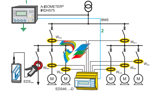
1 - A-ISOMETER® IRDH575
2 - RS-485/BMS protocol
3 - EDS460/EDS461
4 - EDS3090/EDS3091
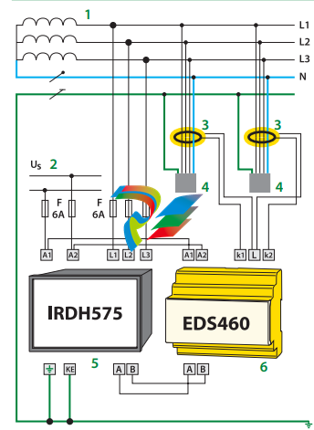
EDS460 system with IRDH575, EDS460 and measuring current transformers W… in a three-phase AC system 1 - 3AC/3NAC/AC 20…575 V 2 - US see ordering information, 6 A fuse recommended. 3 - Current transformers, W series 4 - Loads 5 - A-ISOMETER® IRDH575 6 - Ground fault location device EDS460
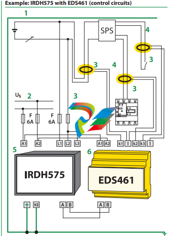
1 - DC 20 V…308 V
2 - US see ordering information, 6 A fuse recommended.
3 - Current transformers, W…/8000 series
4 - Load PLC
5 - A-ISOMETER® IRDH575
6 - Ground fault location device EDS461 Design of an EDS461 system The above example shows an EDS461 device being fed by a PLC in a DC system. Using an EDS461 device is recommended for PLC inputs due to the sensitivity required.
-
 ADLINK Multi-Function DAQ PCI-9222/9223
 -
 ADLINK PICMG Single Board Computers NuPRO-A40H
 -
ADLINK HSL-4XMO HSL-4XMO-TB-D103 HSL-4XMO-CD-N-006
-
 ADLINK industrial computer motherboard NuPRO-965DV
 -
 AADLINK PCI-7442 switch card Digital I/O
 -
 ADLINK PCI-7260 Digital I/O
 -
 ADLINK PICMG Single Board Computers NuPRO-852
 -
 ADlink 6U CompactPCI 2.0 Blades cPCI-6840
 -
 Adlink PICMG Single Board Computers NuPRO-935A
 -
 ADLINK ADLINK NuPRO-841 REV:1.0 PICMG Single Board Computers
 -
ADLINK PCI-8254 / PCI-8258 DSP-based 4/8-axis Advanced Motion Controllers
-
 ADLINK NUPRO-780 PICMG Single Board Computers
 -
 ADLINK USB-7230/7250 Isolated USB Digital I/O Modules
 -
 Adlink Technology 51-37111-0C1 cPCI-R8217 cPCI-R3700A PCB Interface Card
 -
 ADLINK DPAC-3020-11(G) Embedded PC Automation Controller
 -
 ADLINK NuPRO-840 PICMG 1.0 industrial Single Board
 -
 Adlink 6U CompactPCI 2.0 Blades cPCI-6965
 -
 ADLINK PCI-9114DG Multi-Function DAQ Card
 -
 Adlink NuPRO-E43 PICMG Single Board Computers
 -
 Adlink PCI-7856 Distributed Motion Control
 -
 ADLINK Mini-ITX Embedded Boards MI-965
 -
 ADLINK NuPRO-E340 industrial control motherboard
 -
 ADLINK NuPRO-595 Series Full-Size PICMG 1.0 SBC
 -
 ADLINK PCIe-GIE64+ / PCIe-GIE62+ 4 / 2-CH PCI Express® Power over Ethernet Frame Grabbers
 -
 ADLINK CPCI-6910AM-M1G 6U Dual Core Xeon CompactPCI Universal SBC
 -
 ADLINK/AMPRO CM-435-v2/CM-435 Extreme Rugged™ PC/104 Single Board Computer
 -
 ADLINK Technology 51-37111-0C1 PCB Interface Card
 -
 Adlink Centralized Motion Controllers PCI-8164
 -
 ADLINK PCI-7230/33/34 32-CH Isolated DIO PCI Cardsrd
 -
 ADLINK NUPRO-E320DV/NUPRO-E320 industrial control motherboard
 -
 Adlink PCI-8154 Advanced 4-axis Servo & Stepper Motion Controller
 -
 Adlink cPCI-3534/3538-S Series 4/8-port Asynchronous Serial Communications Modules
 -
 ADLINK Adlink Digital I/O PCI-7396
 -
 ADLINK 6U Rear Transition Modules cPCI-R6700 Series
 -
 ADLINK cPCI-6700B Industrial Control Board
 -
ADLINK NuPRO-965/ NuPRO-965LV PICMG Single Board Computers
-
 ADLINK HSL-DI16DO16-M-NN 16-CH Discrete Input 16-CH Discrete Output Module
 -
 Adlink cPCI-6770 6U CompactPCI 2.0 Blades
 -
 ADLINK NuPRO-598 REV A1 INDUSTRIAL CONTROL MOTHERBOARD
 -
 ADLINK PCI-7200 PCI Motion Control Card Acquisition Card 51-12001-0C20
 -
 ADLINK TECHNOLOGY EOS-1200/M4G/SSD32G(G) Industrial Systems
 -
 ADLINK Centralized Motion Controllers PCI-8134
 -
 ADLINK cPCI-HR6847E/M2G-1 COMPACT PCI BOARD
 -
 ADLINK PXIE-8638 BUS EXPANSION MODULE
 -
 ADLINK cPCI-6910 6U CompactPCI 2.0 Blades
 -
 Adlink NuPRO-E42 51-41808-0A30 Industrial Motherboard
 -
 ADLINK IH61-AA400-A4A1E (IMB-M40H) Industrial Motherboard
 -
 ADLINK PCIe-GIE64+ GigE Vision Frame Grabber Card
 -
 ADLINK MXC-6322D(G) Industrial Fanless Computer working
 -
ADLINK CPCI-7300 32-CH 80 MB/s High-Speed Digital I/O Module
-
Adlink cPCI-8168 Advanced 6U Compact PCI 8-Axis Motion Controller
-
 Adlink VME CPU Board cPCI-6626/2710/M4G
 -
 ADLINK cPCI-R6200 high-performance 6U CompactPCI Rear Transition Module (RTM)
 -
Adlink cPCI-7248 48-CH Opto-22 Compatible Digital I/O Module
-
 ADLINK DLAP-211-JNX/DLAP-211-JT2/ DLAP-211-Nan
 -
ADLINK cPCI-3544 4-Port RS-422/485 Isolated Serial Communications Card
-
 Hirschmann MSP30-16040SCZ999HHE2A Manage the basic unit of the industrial DIN-Rail switch
 -
Hirschmann MSP30-16040SCY999HHE2A
-
 Hirschmann RS20-0400S2S2SDAEHC09.0.00 Management-type industrial fast Ethernet switch
 -
 Hirschmann Belden OCTOPUS OS20-002800T5T5T5-TBBY999GMSE3S Manageable industrial Ethernet switch
 -
 HIRSCHMANN OS20-000800T5T5T5-TBBU999H5SE2S
 -
 HIRSCHMANN RS20-0800M4M4SDAEHC09.0.14 industrial switch
 -
 Hirschmann RS20-0800T1T1SDAUHC RS20-0800T1T1SDAE
 -
 Hirschmann MSM20-M2M2M2M2SY9HH9E99.9 Fast Ethernet Media Module
 -
 HIRSCHMANN RS30-1602T1T1SDAEHC09.0.10 industrial switch
 -
 HIRSCHMANN MAR1040-4C4C4C4C9999SMMHPHH Managed Etherne
 -
 HIRSCHMANN MAR1040-4C4C4C4C9999SM9HRHH Managed Etherne
 -
 HIRSCHMANN MAR1040-4C4C4C4C9999SM9HPHH05.1.00 industrial switch
 -
 HIRSCHMANN MM20-P9P9M2T1SAHH Fast Ethernet media module
 -
 HIRSCHMANN MM20-P9T1T1T1SAHH hot-swappable hybrid media module
 -
 HIRSCHMANN MM20-Z6Z6T1M2SAHH Fast Ethernet media module
 -
 HIRSCHMANN MM20-Z6M2M2T1SAHH Fast Ethernet media module
 -
HIRSCHMANN MM20-Z6Z6Z6T1SAHH media module.
-
 HIRSCHMANN MM20-Z6T1T1T1EBH Fast Ethernet media card.
 -
 Hirschmann MM20-Z6T1T1T1SAHH Hot-swappable fast Ethernet media module
 -
 Hirschmann MM20-Z6Z6M2M2EBH media module
 -
 HIRSCHMANN MM20-Z6Z6T1T1SZHH Technical Datasheet & SEO Guide
 -
 HIRSCHMANN MM20-Z6Z6T1T1EBH Technical Datasheet & Overview
 -
 HIRSCHMANN MM20-Z6Z6Z6Z6SZHH Media Module
 -
 HIRSCHMANN MM20-M4M2M2T1SAHH Media Module
 -
.png) HIRSCHMANN MM20-M4T1M2T1SAHH Media Module
HIRSCHMANN MM20-M4T1M2T1SAHH Media Module -
 HIRSCHMANN MM20-M2M2T1T1EBH Media Module
 -
HIRSCHMANN MM20-M2M2T1T1SAHH Media Module
-
HIRSCHMANN MM20-M2T1T1T1TAHH Media Module
-
HIRSCHMANN MM20-M2T1T1T1EBH Media Module
-
 HIRSCHMANN MM20-M2T1T1T1SAHH Media Module
 -
 HIRSCHMANN MM20-M2M2M2M2EBH Industrial Ethernet Media Module
 -
HIRSCHMANN RS20-1600S2S2SDAEHH09.0.14 Ethernet switch
-
 HIRSCHMANN MSM20-M2M2T1T1SY9HH9E99.9.99
 -
HIRSCHMANN MSM20-M2M2M2M2SY9HH9E Ethernet media modul
-
 HIRSCHMANN SPIDER-PL-20-05T1999999TWVHHHH Industrial Ethernet Rail Switch
 -
 Hirschmann SPIDER-PL-20-07T1M2M299TWVHHHH Industrial ETHERNET Rail Switch
 -
Hirschmann (Belden) RS20-1600M2M2SDAEHC09.1.00 DIN-rail managed industrial Fast Ethernet switch
-
 Hirschmann (Belden) RS30-1602O6O6TDAPHC09.1.00 DIN-rail managed industrial Ethernet switch
 -
 Hirschmann (Belden) RS30-2402O6T1SDAPHH09.0.13 DIN-rail industrial Ethernet switch
 -
Hirschmann (Belden) SPIDER-PL-20-04T1S29999TY9HHHH Ethernet DIN-rail switch
-
 HIRSCHMANN RS20-1600T1T1SDAUHX Switch
 -
 HIRSCHMANN BRS42-0012OOOO-SPCZ99HHSES industrial switch
 -
 Hirschmann RS20-0800S2S2TDHPHH09.0.14 Fast Ethernet DIN rail switch.
 -
HIRSCHMANN MM20-Z6Z6M2M2SAHH Hybrid Fast Ethernet Media Module
-
HIRSCHMANN MM20-Z6Z6T1T1SAHH hot-swappable hybrid Fast Ethernet Media Module
-
 HIRSCHMANN MM20-P9P9T1T1SAHH Hybrid Fast Ethernet Media Module
 -
 HIRSCHMANN MM20-M4T1T1T1SAHH Hybrid Fast Ethernet Media Module
 -
HIRSCHMANN MM20-M4M4T1T1SAHH Hybrid Fast Ethernet Media Module
-
 HIRSCHMANN MM20-M2M2M2M2SZHH Ethernet media module
 -
HIRSCHMANN MM20-M2M2M2M2SAHH Ethernet media module
-
 HIRSCHMANN MM20-T1T1T1T1EBH 4-port Fast Ethernet Copper Cable Media Module
 -
HIRSCHMANN MM20-T1T1T1T1SAHH 4-port Fast Ethernet Copper Cable Media Module
-
HIRSCHMANN MM20-Z6Z6EBH Hot-swappable fast Ethernet media module
-
HIRSCHMANN MM20-Z6Z6SAHH Ethernet media module
-
HIRSCHMANN MM20-Z6Z6Z6Z6EBH Industrial Media Module
-
 MSM40-T1T1T1TZ9HH9E99.9.99 HIRSCHMANN Switch
 -
 HIRSCHMANN MS20-0800SAAEHC / MS20-0800SAAEHC0 8-port modular Layer 2 management Ethernet switch
 -
 Hirschmann RSPM20-4T14T1SZ9HHS9 Switch RSPM20-4T14T1SZ9HHS9
 -
 HIRSCHMANN RS20-1600M2M2SDAEHH09.1. RS20/30/40 Managed Switch configurator
 -
HIRSCHMANN RS20-1600M2M2SDAEHX09.0.00 Ethernet switch
-
 HIRSCHMANN BELDEN SPIDER-PL-20-07T1M2M299TY9HHHH / SPIDERPL2007T1M2M299TY9HHHH
 -
HIRSCHMANN MM3-1FXS2/3TX1 Switching Board Module
-
HIRSCHMANN RSPE30-24044O7T99-ECCP999HHSE2A08.1.00 Industrial-grade fanless management-type Ethernet switch
-
 HIRSCHMANN RS30-1602OOZZSDAEHC09.1.00 DIN-rail-mounted managed Layer 2 Ethernet switch
 -
 HIRSCHMANN MACH104-20TX-F Managed 24-port Full Gigabit 19" Switch
 -
 HIRSCHMANN Switch RS20-0800M4M4SDAE
 -
Hirschmann RS30-1602O6O6SDAEHH09.1. Management-type Ethernet switch
-
 Hirschmann RS30-1602OOZZSDAEHC09.0.10 Open rack-style Ethernet switch
 -
 HIRSCHMANN RSPE30-24044O7T99-SCCV999HHSI2SXX.X.XX High-Availability Seamless Redundancy
 -
HIRSCHMANN RSPE30-24044O7T99-SCCZ999HHSE2A DIN-rail Ethernet switch
-
HIRSCHMANN MM2-4TX1-EEC switch
-
HIRSCHMANN MSM40-T1T1T1T1TZ9HH9E99.9.99 Module


