
A-BPLC-5 Backup Communication Module
A PLC-5 backup system contains two of each of the following hardware
components:
PLC-5 processor module
Processor:* Catalog Number:
PLC-5/11 series A, revision B or later 1785-L11B
PLC-5/15 series B, any revision 1785-LT series B
PLC-5/20 series A, revision B or later 1785-L20B
PLC-5/25 any revision 1785-LT2
PLC-5/30 series A, revision C or later 1785-L30B
PLC-5/40 series A, revision F or later
or series B, revision C or later
1785-L40B
PLC-5/60 series A, revision F or later
or series B, revision C or later
1785-L60B
PLC-5/80 series C, revision A or later 1785-L80B
*
Contact your Allen-Bradley Sales Office or your Allen-Bradley distributor
for additional PLC-5 processors that can be configured with the
1785-BCM modules.
1785-BCM module
1785-BEM module (when applicable)
power supply
local chassis
Figure 1.1 shows a typical PLC-5 backup configuration using PLC-5/15
processors and 1785-BCM modules. Figure 1.2 shows a typical PLC-5
backup configuration using PLC-5/40 or PLC-5/60 processors, 1785-BCM
modules, and 1785-BEM modules.
A PLC-5 system configured with 1785-BCM modules provides high speed
backup communication and switchover of the Data Highway Plus and
remote I/O links. In this section we:
show a typical PLC-5 backup configuration
explain how the backup system works
describe the role of the 1785-BCM module (including 1785-BEM
module)
A Typical PLC-5 Backup Configuration
You must use BCM series B, revision C or later if you are using PLC-5/20,
-5/30, -5/40, or -5/60 processors.
A PLC-5 backup system contains two of each of the following hardware
components:
PLC-5 processor module
Processor:* Catalog Number:
PLC-5/11 series A, revision B or later 1785-L11B
PLC-5/15 series B, any revision 1785-LT series B
PLC-5/20 series A, revision B or later 1785-L20B
PLC-5/25 any revision 1785-LT2
PLC-5/30 series A, revision C or later 1785-L30B
PLC-5/40 series A, revision F or later
or series B, revision C or later
1785-L40B
PLC-5/60 series A, revision F or later
or series B, revision C or later
1785-L60B
PLC-5/80 series C, revision A or later 1785-L80B
*
Contact your Allen-Bradley Sales Office or your Allen-Bradley distributor
for additional PLC-5 processors that can be configured with the
1785-BCM modules.
1785-BCM module
1785-BEM module (when applicable)
power supply
local chassis
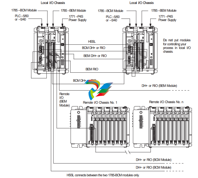
Figure 1.1 shows a typical PLC-5 backup configuration using PLC-5/15
processors and 1785-BCM modules. Figure 1.2 shows a typical PLC-5
backup configuration using PLC-5/40 or PLC-5/60 processors, 1785-BCM
modules, and 1785-BEM modules.
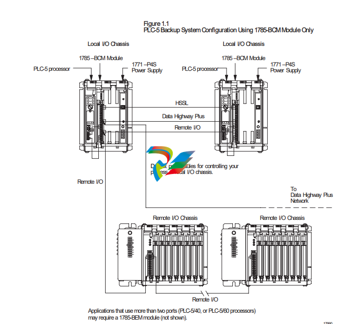
Figure 1.2
PLC-5 Backup System Configuration Using 1785-BCM
and 1785-BEM Modules
How the PLC-5 Backup System Works
In the PLC-5 backup configuration, one system (consisting of one PLC-5
processor, 1785-BCM module, power supply, and chassis) controls the
operation of the remote I/O. This system is referred to as the primary
system. The other system is ready to take control of the remote I/O in the
event of a fault in the primary system. This is referred to as the
secondary system. The PLC-5 backup system does not back up local I/O;
therefore, do not install I/O in the local chassis.
Data Transfer
During normal operation, the primary system sends remote input and data
table data to the secondary system so that in the event of a switchover, the
secondary system (which becomes the new primary system) has the same
data.
Remote I/O data is automatically transferred over the High-Speed Serial
Link (see Figure 1.1). This transfer is independent of the application
program.
Data table values are transferred from the primary to the secondary system
with block transfer instructions that you include in your ladder program.
You do not have to transfer data table values if not necessary for your
application. Figure 1.3 shows how data table data is transferred from the
primary to the secondary system.
Figure 1.3
Transfer of Data Table Data From the Primary to Secondary System
Switchover
Should a fault occur in the primary processor, control switches to the
secondary system in less than 50 ms (maximum). When a switchover
occurs, the outputs in the remote I/O maintain their last state until they
come under the control of the secondary processor.
However, keep in mind that the program scans of the two processors are
not synchronized. This means that the secondary processor may be
scanning all, none, or only part of the program (at your discretion). This
manual explains the switchover process, and provides guidelines for
developing programs for your PLC-5 backup system. (For more
information about switchover, refer to Chapter 6, “Switchover
Considerations.”)
Role of the 1785-BCM Series B Module
As an integral part of the backup system, the 1785-BCM modules enable
high speed communication between the two PLC-5 processors, and permit
the secondary processor to assume control of the process. In addition, the
1785-BCM module provides:
high speed transfer of the data table values from the primary to the
secondary system, to ensure that the secondary system’s data table is a
copy of the primary system’s
a buffer of 4K words for data table values
-
 Hirschmann RS20-1600M2T1SDAEHH03.1.02 Rail Switch
 -
 Hirschmann BRS30-24TX Industrial Rail Switch
 -
 Hirschmann RSPM20-4T14T1EV9HHS999.9.99 Managed Ethernet Switch
 -
 Hirschmann BELDEN RS40-0009CCCCSDAPHH09.0.14 / RS400009CCCCSDAPHH09014
 -
Hirschmann RS40 Rail Switch RS40-0009CCCCSDAE
-
 Hirschmann BELDEN RS30-0802T1T1SDAP / RS300802T1T1SDAP Fully Managed Layer 2 Compact Rail Switch
 -
 Hirschmann BELDEN RS20-0800M2M2SDAUHH / RS200800M2M2SDAUHH
 -
 Hirschmann EAGLE30-04022O6TT999SCCY9HSE3F Industrial Firewall Router Switch
 -
 Hirschmann RS20-1600T1T1SDAEHH09.0.14 RS20 Rail Mount Ethernet Switch
 -
 Hirschmann EAGLE0200T1T1TDDY90000HHE05.3.03 Industrial Security Router
 -
Hirschmann - BELDEN MIPP-AD-1L9P
-
 HIRSCHMANN RSPM20-4Z64Z6TV9HHS9 942 106-999 RAIL SAFETY SWITCH
 -
 HIRSCHMANN FIBEROPTIC MODULE FIP P/N: OZDFIPG3T
 -
 HIRSCHMANN RS20-1600M2M2SDAUHH Ethernet rack-mounted switch
 -
 HIRSCHMANN BELDEN RS20-0400T1T1SDAEHH04.0.01 / RS200400T1T1SDAEHH04001
 -
HIRSCHMANN MM2-4FXM3 MICE Media Module
-
HIRSCHMANN RS20-0800M2M2SDAE Industrial Ethernet Rail Switch
-
 Hirschmann RS20-2400T1T1SDAP / RS20-2400T1T1SDAPHH05.0.02
 -
 GE MLJ1005B010H00C MLJ Digital Synchromism Check
 -
 ALSTOM MICROTECH DX21-M2 Digital Excitation Controller
 -
HIRSCHMANN BRS20-1200ZZZZ-STCY99HHSES
-
 HIRSCHMANN MM3-4FXM2 MICE Media Module
 -
Hirschmann RSB20-0800T1T1SAABHH 8Port ENet Rail Switch RSB20
-
 Hirschmann MACH102-8TP Ethernet Switch
 -
 SAACKE DDZ-M marine steam pressure atomizer
 -
 SAACKE SKV-A marine rotary cup atomizer
 -
 SAACKE Seavis HMI05e
 -
 Kollmorgen MMC-SD-2.0-230 Servo Drive 100-240VAC 2KW 10A Output 3PH 100-240VAC
 -
 Kollmorgen Servo drive CR10550
 -
 Kollmorgen AKD-P01207-NACN-0054 Servo Driver
 -
 Kollmorgen S406M-CA-036 Servostar
 -
.png) Kollmorgen AKD-B02407-NAAN-0000 Digital Servo Drive
Kollmorgen AKD-B02407-NAAN-0000 Digital Servo Drive -
 Kollmorgen SERVOSTAR S406AM-CA Digital Servo Drive
 -
 KOLLMORGEN SERVOSTAR 603-AS SERVO AMPLIFIER_SERVOSTAR603AS_S60301
 -
Kollmorgen S700 Servo Controller (S70602-NANANA-NA)
-
 Kollmorgen MPK411 controller
 -
 KOLLMORGEN MMC-SD-1.3-460-D Smart Drive
 -
 KOLLMORGEN AKM21C-CKB2AA-00 / AKM21CCKB2AA00 Servomotor
 -
 BECKHOFF AX5106-0000-0200 | Digital Compact Servo Drives 1-channel
 -
 BECKHOFF C3620-0000 INDUSTRIAL COMPUTER (MOTORSHELVES)
 -
 Beckhoff EK1960-0000 TwinSAFE Compact Controller
 -
 Beckhoff C6930-0050 Control Cabinet Industrial PC
 -
 Beckhoff CP7711-0001-0030 Industrial Computer Detection
 -
 Beckhoff CX1001-0111 Embedded PC CPU Module
 -
 Beckhoff C6017-0020 | Ultra-compact Industrial PC
 -
 Beckhoff EK1322 | 2-port EtherCAT P junction with feed-in
 -
 Beckhoff CP2219-0010 Panel
 -
 BECKHOFF C6015-0020 ULTRA COMPACT INDUSTRIAL PC
 -
 BECKHOFF CX2030-0120/Standard CPU Module Embedded PC Windows PLC controller
 -
 Beckhoff CP7721-1090-0020 Panel PC
 -
 Beckhoff PC CPU Module CX5130-0175
 -
 Beckhoff C6920-0050 Control Cabinet
 -
 Beckhoff EL6631 EtherCAT 2-Port Communication Interface, Profinet RT Controller
 -
 Beckhoff CP6202-0001-0060 touch screen panel PC
 -
 Beckhoff CP3916-1002-0000 Multi-Touch Control Panel
 -
 Beckhoff EP1809-0021 | EtherCAT Box, 16-channel digital input, 24 V DC, 3 ms, M8Preferred type
 -
 Beckhoff CX8190 PLC Embedded Industrial PC Ethernet Controller
 -
 Beckhoff CX2100-0914 Power Supply for External
 -
 Beckhoff Automation CP6906-0001-0000 HMI
 -
 Beckhoff EP7342-0002 Module
 -
 Beckhoff CX1020-0112 / CX1100-0910 / CX1020-N010 / CX1100-0003 Windows CPU
 -
 Beckhoff EP7211-0034 EtherCAT Box 1 Channel Motion Interface
 -
 Beckhoff C6240-0030 Control cabinet Industrial PC
 -
 beckhoff motherboard CB1052-0004 CB1052-0004
 -
 Beckhoff AX2006-AS Servo Drive / Variable Frequency Drive
 -
BECKHOFF CP6207-0001-0020 NSMP
-
 Beckhoff C6930-1142-0060 Industrial Computer
 -
 Beckhoff FC7501-0000 interface card
 -
 Beckhoff CX5140-0175 Embedded PC PLC CPU CX5140 Industrial Controller
 -
 Beckhoff CP7802-1100-0010: High-End IP65 Control Panel with DVI/USB Extended Interface
 -
BECKHOFF CP3716-1058-0010 CONTROL PANEL
-
 Beckhoff AX8108-0000 Single-Axis Module
 -
 Beckhoff CU8851-0000 | USB extension, USB Extended 2.0 receiver box
 -
Beckhoff C6017-0030 | Ultra-compact Industrial PC
-
 Beckhoff CX1001-0120/CX10010120.cx1000-n001.cx1000-n000 System Overview
 -
 Beckhoff CPU Module CX5140-0155/4GB CPU Module
 -
 Beckhoff CP6533-0001-005: Built-in Panel PC with High-Definition Multi-Touch Control
 -
 Beckhoff EL5042 | EtherCAT Terminal, 2-channel encoder interface, BiSS® C
 -
 Beckhoff C6920-1080-0040: Premium Control Cabinet Industrial PC
 -
 Beckhoff C6920-0060 | Control cabinet Industrial PC
 -
 Beckhoff Embedded-PC CX5010-1121
 -
 Beckhoff CB3050-0010 Mainboard Motherboard
 -
 Beckhoff PLC module CX1020-0000 Basic CPU module (service phase)
 -
 Beckhoff CP7812-1056-0010 15" Multitouch Display Control Panel
 -
 Beckhoff CX5120-0115 /2GB Controller Module
 -
 Beckhoff CP7201-1000-0000 Industrial Panel PC
 -
 Beckhoff Servo Motor AM8061-0JH1-0000
 -
 BECKHOFF CP6503-0001-0050 Built-in Panel PC
 -
Beckhoff CP3919-0010 Display G190ETN01.2 19" PCT V04. Multi-touch Control Panel
-
 Beckhoff CX5110-0112-9020/000368201 Embedded PC Intel Atom Processor
 -
 Beckhoff AX8206-0000 Dual-Axis Module
 -
Beckhoff Nail Operating Terminal CP7032-1031-0010
-
Beckhoff AM8042-0EH1-0000 Servomotor 4.10 Nm (M0), F4 (87 mm)
-
 Beckhoff EK9300 Beckhoff CPU Module
 -
Beckhoff CP3224-0020 Multitouch-Panel-PC
-
 Beckhoff CP2712-0000 12.1" 24VDC Touch Screen WMD0
 -
 BECKHOFF CX5240-0195 / 0000289234 Embedded PC 40 GB CFast Card
 -
 Beckhoff CP6932-1000-0000 Control Panel
 -
 BECKHOFF CX5120-0121 PLC Module
 -
 Beckhoff EL3218 | EtherCAT Terminal, 8-channel analog input
 -
Beckhoff C6640-0050 | Control cabinet Industrial PC
-
 Beckhoff Cx5130-0120/4GB Embedded-PC
 -
 BECKHOFF CX2030-0122 PLC PROCESSOR
 -
 BECKHOFF CX5020-0122 Controller Module
 -
 Beckhoff CP3915-0000 Multitouch Panel
 -
 BECKHOFF EL3014 | EtherCAT Terminal
 -
 BECKHOFF Industrial Computer c6920-1057-0030
 -
 Beckhoff CX5130-0141/4GB CX5130-0141 Embedded PC
 -
 Beckhoff C6240-1052-0040 4-086-06-3073 Industrial Computer
 -
 Beckhoff CX5140-0135 /4GB High-Performance Embedded Industrial PC
 -
 Beckhoff C6515-1001-0000 Industrial PC
 -
 Beckhoff AX5103-0000-0200 - Digital Compact Servo Drives
 -
 Beckhoff CX2030-0130-1003/4GB Basic CPU module
 -
 Beckhoff AX8620-0000 Power Supply Module
 -
 Beckhoff CX9020-0111 module with
 -
 Beckhoff EL7332 PLC Module
 -
 BECKHOFF CP7709-0001-0020 HMI
 -
 Beckhoff CX5120-0155/2GB Embedded PC
 -
 BECKHOFF CP7037-1037-0010 OPERATOR INTERFACE TOUCHSCREEN
 -
 Beckhoff EK9000 | ModbusTCP/UDP Bus Coupler
 -
 Beckhoff Touch Panel Screen CP6020 -0000-0000
 -
 Beckhoff CX2020-0121 Module FAST Shipping
 -
 Beckhoff CX2030-0125 Basic CPU Module
 -
 Beckhoff CP3918-0000 Multi-Touch 18.5" Control Panel
 -
 Automotion LC4A00010 DC BL Motor Control, ATS, Sub Assy, SCP, 115VAC,
 -
 500T-115VAC - VAS ENGINEERING - DORIC 500 SERIES DIGITAL TEMP INDICATOR
 -
 Honeywell X-DCS2000/EN Digital Integrated System Manager 50/60Hz 100-240V #4
 -
 Kollmorgen S60600 Servostar600 606-Fan 4 kVA, 6 A, 3 X 230 - 480 V


