
A-BMicroLogix 1000 Programmable Controllers
Important User Information
Because of the variety of uses for the products described in this publication, those responsible
for the application and use of these products must satisfy themselves that all necessary steps
have been taken to assure that each application and use meets all performance and safety
requirements, including any applicable laws, regulations, codes and standards. In no event will
Allen-Bradley be responsible or liable for indirect or consequential damage resulting from the
use or application of these products.
Any illustrations, charts, sample programs, and layout examples shown in this publication are
intended solely for purposes of example. Since there are many variables and requirements
associated with any particular installation, Allen-Bradley does not assume responsibility or
liability (to include intellectual property liability) for actual use based upon the examples
shown in this publication.
Allen-Bradley publication SGI-1.1, Safety Guidelines for the Application, Installation and Maintenance
of Solid-State Control (available from your local Allen-Bradley office), describes some important
differences between solid-state equipment and electromechanical devices that should be taken
into consideration when applying products such as those described in this publication.
Reproduction of the contents of this copyrighted publication, in whole or part, without
written permission of Rockwell Automation, is prohibited.
Throughout this publication, notes may be used to make you aware of safety considerations.
The following annotations and their accompanying statements help you to identify a potential
hazard, avoid a potential hazard, and recognize the consequences of a potential hazard:
WARNING
!
Identifies information about practices or circumstances that can cause
an explosion in a hazardous environment, which may lead to personal
injury or death, property damage, or economic loss.
ATTENTION
!
Identifies information about practices or circumstances that can lead
to personal injury or death, property damage, or economic loss.
IMPORTANT Identifies information that is critical for successful application and
understanding of the product.
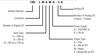
Overview Install your controller using these installation instructions. The only tools you require are a Flat head or Phillips head screwdriver and drill. Catalog Number Detail The catalog number for the controller is composed of the following:
For More Information
Related Publications
If you would like a manual, you can:
• download a free electronic version from the internet:
http://literature.rockwellautomation.com
• purchase a printed manual by contacting your local Allen-Bradley distributor or
Rockwell Automation representative
For Refer to this Document Pub. No.
A description on how to use your MicroLogix 1000
programmable controllers. This manual also contains
status file data and instruction set information.
MicroLogix 1000 Programmable
Controllers User Manual
1761-6.3
A procedural manual for technical personnel who use the
Allen-Bradley Hand-Held Programmer (HHP) to monitor
and develop control logic programs for the MicroLogix
1000 controller.
MicroLogix 1000 with Hand-Held
Programmer (HHP) User Manual
1761-6.2
More information on proper wiring and grounding
techniques.
Industrial Automation Wiring and
Grounding Guidelines
1770-4.1
The procedures necessary to install and connect the AIC+
and DNI.
Advanced Interface Converter
(AIC+) and DeviceNet Interface
(DNI) Installation Instructions
1761-5.11
A more detailed description on how to install and use your
AIC+ Advanced Interface Converter.
AIC+ Advanced Interface Converter
User Manual
1761-6.4
A more detailed description on how to install and use your
DeviceNet Interface.
DeviceNet Interface User Manual 1761-6.5
A more detailed description on how to install and use your
Ethernet Interface.
Ethernet Interface User Manual 1761-UM006
Safety Considerations
This equipment is suitable for use in Class I, Division 2, Groups A, B, C, D or non-hazardous
locations only (when product or packing is marked).
Use only the following communication cables in Class I, Division 2, Hazardous Locations.
WARNING
!
Explosion Hazard:
• Substitution of components may impair suitability for Class I,
Division 2.
• Do not replace components or disconnect equipment unless
power has been switched off and the area is known to be
non-hazardous.
• Do not connect or disconnect connectors while circuit is live
unless area is known to be non-hazardous.
• This product must be installed in an enclosure. All cables
connected to the product must remain in the enclosure or be
protected by conduit or other means.
• The interior of the enclosure must be accessible only by the use
of a tool.
• For applicable equipment (for example, relay modules), exposure
to some chemicals may degrade the sealing properties of the
materials used in these devices:
– Relays, epoxy
It is recommended that you periodically inspect these devices for
-
 CTI 2500S-27-1750 Slice I/O, Ethernet, RS232/485. 900MHz, 2DIO / 4UAI / 2AI
 -
 CTI 2500S-26-1750 Slice I/O, Ethernet, RS232/485. 900MHz, 8DIO / 2UAI
 -
 CTI 2500S-23-1750 Slice I/O, Ethernet, RS232/485. 900MHz, 4DI / 4DO / 2UAI / 2AO
 -
 CTI 2500S-27-1550 Slice I/O, RS232/485. 2DIO / 4UAI / 2AI
 -
 CTI 2500S-26-1550 Slice I/O, RS232/485. 8DIO / 2UAI
 -
 CTI 2500S-23-1550 Slice I/O, RS232/485. 4DI / 4DO / 2UAI / 2AO
 -
 CTI 2500S-27-1050 Slice I/O, Ethernet, 2DIO / 4UAI / 2AI
 -
 CTI 2500S-26-1050 Slice I/O, Ethernet, 8DIO / 2UAI
 -
 CTI 2500S-23-1050 Slice I/O, Ethernet, 4DI / 4DO / 2UAI / 2AO
 -
 CTI 2500C-32F-CJC 32-Pin Field Wiring Connector with Cold Junction Compensation
 -
 CTI 2500C-32F 32-Pin Field Wiring Connector
 -
 CTI 2500C-8-TC Eight Thermocouple Inputs
 -
 CTI 2500C-8-RTD Eight RTD Inputs
 -
 CTI 2500C-8-RL-FC 8 Form-C Relay Outputs
 -
 CTI 2500C-8-IDO-24V 8 Isolated 24VDC Outputs
 -
 CTI 2500C-8-IDO-120V 8 Isolated 120VAC Outputs
 -
 CTI 2500C-16-DO-24V Sixteen 24VDC Digital Outputs
 -
 CTI 2500C-16-DO-120V Sixteen 120VAC Digital Outputs
 -
.png) CTI 500C-16-IDI-24V Sixteen Isolated 24V AC/DC Digital Inputs
CTI 500C-16-IDI-24V Sixteen Isolated 24V AC/DC Digital Inputs -
 CTI 2500C-16-IDI-120V Sixteen Isolated 120V AC/DC Digital Inputs
 -
 CTI 2500C-16-DIDO-SIM Sixteen Digital Input and Output SImulator
 -
 CTI 2500C-16-DI-24V Sixteen 24V AC/DC Digital Inputs
 -
 CTI 2500C-16-DI-120V Sixteen 120V AC/DC Digital Inputs
 -
 CTI 2500C-RBC-RS485 RS485 Remote Base Controller
 -
 CTI 2500C-RBC-PRF Profibus Remote Base Controller
 -
 CTI 2500C-PS-24V-35 35-Watt DC Power Supply
 -
 CTI 2500C-PS-120V-35 35-Watt AC Power Supply
 -
 CTI 2500C-R8 Eight-Slot Base
 -
 CTI 2500C-R4 Four-Slot Base
 -
 CTI 2500C-R16 Sixteen-Slot Base
 -
 CTI 2500C-2572-B Fast Ethernet TCP/IP Adapter
 -
 CTI 2500C-J750 Compact Janus PAC with 3MB Project Memory
 -
 CTI 2500C-C300 CPU with 512K User Memory
 -
 CTI 2500C-C200 CPU with 256K User Memory
 -
 CTI 2500C-C100 CPU with 128K User Memory
 -
 CTI 2500C-8-AO 8 Analog Outputs
 -
 CTI 2500C-8-AI 8 Analog Inputs
 -
 CTI 2559-FCAL Precision Calibration Connector
 -
 CTI 2559-FPC 40-Position Screw-Terminal Connector
 -
 CTI 2500-RFC PLC to RF Modem Cable
 -
 CTI 2500-40F 40-Position Standard Screw-Terminal Connector
 -
 CTI 2505 Vibration Sensor Interface Module
 -
 CTI 2554-A 4-Channel Isolated High Speed Counter Module
 -
 CTI 2553-A 2-Channel Mag Meter Input Module
 -
 CTI 2502 2-Channel High Speed Counter Input Module
 -
 CTI 2559-TC 8-Channel Thermocouple Input Module
 -
 CTI 2556-A 16-Channel Isolated Thermocouple Input Module
 -
 CTI 2556 16-Channel Isolated Thermocouple Input Module
 -
 CTI 2551-A 8-Channel Isolated Thermocouple Input Module
 -
 CTI 2559-RTD 8-Channel RTD Input Module
 -
 CTI 2557-A 16-Channel RTD Input Module
 -
 CTI 2557 16-Channel RTD Input Module
 -
 CTI 2552-A 8-Channel Isolated RTD Input Module
 -
 CTI 2534 8-Point Form-C Relay Output Module
 -
 CTI 2532 16-Point Form-A Relay Output Module
 -
 CTI 2531 32-Point Form-A Relay Output Module
 -
 CTI 2530 8-Point Form-C Relay Output Module
 -
 CTI 2562 8-Channel Analog Output Module
 -
 CTI 2560-A 8-Channel Isolated Analog Output Module
 -
 CTI 2501 8in/4out Analog Module
 -
 CTI 2558 8-Channel Analog Input Module
 -
 CTI 2555-A 16-Channel Analog Input Module
 -
 CTI 2550-A 8-Channel Isolated Analog Input Module
 -
 CTI 2599 8/16/32-Point AC Output Module
 -
 CTI 2598-8 8-Point AC Output Module
 -
 CTI 2598 8/16-Point AC Output Module
 -
 CTI 2597 8/16/32-Point DC Output Module
 -
 CTI 2596-8 8-Point DC Output Module
 -
 CTI 2596 8/16-Point DC Output Module
 -
 CTI 2595 16-Point TTL/Word Output Module
 -
 CTI 2591-EF 16-Point Isolated 11-146 VDC Output with Front Panel Accessible Fuses
 -
 CTI 2591-A 16-Point Isolated 11-146 VDC Output Module
 -
 CTI 2590-EF 16-Point Isolated 20-132 VAC Output with Front Panel Accessible Fuses
 -
 CTI 2590-A 16-Point Isolated Discrete 20-132 VAC Output Module
 -
 CTI 2589-B 8/16/32-Point Universal Discrete Input Module
 -
 CTI 2589-A 8/16/32-Point Universal Discrete Input Module
 -
 CTI 2588-8 8-Point Universal Discrete Input Module
 -
 CTI 2585 16-Point TTL/Word Input Module
 -
 CTI 2582 16-Point Isolated 125 VDC Input Module
 -
 CTI 2581 16-Point Isolated 12-56 VDC Input Module
 -
 CTI 2580 16-Point Isolated 95-132 VAC Input Module
 -
 CTI 2500-TAP RS485 Network Tap
 -
 CTI 2500-RIO-B RS485 Remote Base Controller
 -
 CTI 2500-RIO-A RS485 Remote Base Controller
 -
 CTI 2500-RBC Profibus Remote Base Controller
 -
 CTI 2515-A 100-Watt AC/DC Power Supply with Redundancy Support
 -
 CTI 2515 100-Watt AC Power Supply (MATURE - replaced by 2515-A)
 -
 CTI 2513-A 75-Watt DC Power Supply with Redundancy Support
 -
 CTI 2513 75-Watt 24VDC Power Supply
 -
 CTI 2512-A 75-Watt AC/DC Power Supply with Redundancy Support
 -
 CTI 2512 75-Watt AC/DC Power Supply
 -
 CTI 2510 125 VDC Power Supply
 -
 CTI 2500-SSB Single Slot Blank Front Panel
 -
 CTI 2500-R11-A Eleven-Slot Redundant Base
 -
 CTI 2500P-R16 Sixteen-Slot Base with High-Speed Channel
 -
 CTI 2500P-R8 Eight-Slot Base with High-Speed Channel
 -
 CTI 2500P-R4 Four-Slot Base with High-Speed Channel
 -
 CTI 2541 Redundant Processor Manager Module
 -
 CTI 2577 Profibus DP Slave Adapter
 -
 CTI 2573-MOD Serial Interface Adapter with MODBUS
 -
 CTI 2572-AF Fast Ethernet TCP/IP Adapter with Optical Fiber Connection
 -
 CTI 2572-A Fast Ethernet TCP/IP Adapter
 -
 CTI 2572 Ethernet TCP/IP Adapter
 -
 CTI 2572-B Fast Ethernet TCP/IP Adapter
 -
 CTI 2576 DeviceNet™ Scanner Module (MATURE)
 -
 CTI 2500P-ECC1 Ethernet Communications Coprocessor
 -
 CTI 2500P-JACP Janus Application Coprocessor
 -
 CTI 2500P-ACP1 Application Coprocessor (MATURE - replaced by 2500P-JACP)
 -
 CTI 2500P-J450 Janus PAC with 2MB Project Memory
 -
 CTI 2500-C400 CPU with 3072K User Memory
 -
 CTI 2500-C300 CPU with 512K User Memory
 -
 CTI 2500-C200 CPU with 256K User Memory
 -
 CTI 2500-C100 CPU with 128K User Memory
 -
 CTI 2500P-J750 Janus PAC with 3MB Project Memory
 -
 Shinkawa WHF3006M Displacement Converter
 -
Shinkawa JBP-220 (P-24-94A / P-24-94B) Circuit Board Module
-
 SHINKAWA WKN-142K5 2-WIRE VIBRATION TRANSDUCER
 -
Shinkawa FRP-321 (P-26-54A / P-26-54B) Circuit Board Module
-
 Shinkawa IOP-160 (P-25-72A / P-25-72B) Circuit Board Module
 -
 Shinkawa PK-147B-1 / PK-147A-1 Circuit Board Module
 -
 Shinkawa CPP-91A Circuit Board Module
 -
 Shinkawa FRP-177 PCB Module
 -
 Shinkawa CPP-127 (P-26-74A / P-26-74B) Circuit Board Module
 -
Shinkawa FRP-227 (P-24-86A / P-24-86B) Circuit Board Module
-
 Shinkawa MDP-104 (P-25-83A / P-25-83B) Circuit Board Controller
 -
 Shinkawa VK-143P2 High-precision eddy current sensor driver/signal conditioner
 -
 Shinkawa FRP-226 (P-24-86A / P-24-86B) Circuit Board Module
 -
Shinkawa CPP-107A P-22-99A P-22-99B Circuit Board Module


