
A-BMicroLogix 1000 Programmable Controllers
Important User Information
Because of the variety of uses for the products described in this publication, those responsible
for the application and use of these products must satisfy themselves that all necessary steps
have been taken to assure that each application and use meets all performance and safety
requirements, including any applicable laws, regulations, codes and standards. In no event will
Allen-Bradley be responsible or liable for indirect or consequential damage resulting from the
use or application of these products.
Any illustrations, charts, sample programs, and layout examples shown in this publication are
intended solely for purposes of example. Since there are many variables and requirements
associated with any particular installation, Allen-Bradley does not assume responsibility or
liability (to include intellectual property liability) for actual use based upon the examples
shown in this publication.
Allen-Bradley publication SGI-1.1, Safety Guidelines for the Application, Installation and Maintenance
of Solid-State Control (available from your local Allen-Bradley office), describes some important
differences between solid-state equipment and electromechanical devices that should be taken
into consideration when applying products such as those described in this publication.
Reproduction of the contents of this copyrighted publication, in whole or part, without
written permission of Rockwell Automation, is prohibited.
Throughout this publication, notes may be used to make you aware of safety considerations.
The following annotations and their accompanying statements help you to identify a potential
hazard, avoid a potential hazard, and recognize the consequences of a potential hazard:
WARNING
!
Identifies information about practices or circumstances that can cause
an explosion in a hazardous environment, which may lead to personal
injury or death, property damage, or economic loss.
ATTENTION
!
Identifies information about practices or circumstances that can lead
to personal injury or death, property damage, or economic loss.
IMPORTANT Identifies information that is critical for successful application and
understanding of the product.
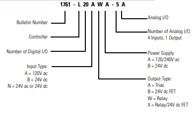
Overview Install your controller using these installation instructions. The only tools you require are a Flat head or Phillips head screwdriver and drill. Catalog Number Detail The catalog number for the controller is composed of the following:
For More Information
Related Publications
If you would like a manual, you can:
• download a free electronic version from the internet:
http://literature.rockwellautomation.com
• purchase a printed manual by contacting your local Allen-Bradley distributor or
Rockwell Automation representative
For Refer to this Document Pub. No.
A description on how to use your MicroLogix 1000
programmable controllers. This manual also contains
status file data and instruction set information.
MicroLogix 1000 Programmable
Controllers User Manual
1761-6.3
A procedural manual for technical personnel who use the
Allen-Bradley Hand-Held Programmer (HHP) to monitor
and develop control logic programs for the MicroLogix
1000 controller.
MicroLogix 1000 with Hand-Held
Programmer (HHP) User Manual
1761-6.2
More information on proper wiring and grounding
techniques.
Industrial Automation Wiring and
Grounding Guidelines
1770-4.1
The procedures necessary to install and connect the AIC+
and DNI.
Advanced Interface Converter
(AIC+) and DeviceNet Interface
(DNI) Installation Instructions
1761-5.11
A more detailed description on how to install and use your
AIC+ Advanced Interface Converter.
AIC+ Advanced Interface Converter
User Manual
1761-6.4
A more detailed description on how to install and use your
DeviceNet Interface.
DeviceNet Interface User Manual 1761-6.5
A more detailed description on how to install and use your
Ethernet Interface.
Ethernet Interface User Manual 1761-UM006
Safety Considerations
This equipment is suitable for use in Class I, Division 2, Groups A, B, C, D or non-hazardous
locations only (when product or packing is marked).
Use only the following communication cables in Class I, Division 2, Hazardous Locations.
WARNING
!
Explosion Hazard:
• Substitution of components may impair suitability for Class I,
Division 2.
• Do not replace components or disconnect equipment unless
power has been switched off and the area is known to be
non-hazardous.
• Do not connect or disconnect connectors while circuit is live
unless area is known to be non-hazardous.
• This product must be installed in an enclosure. All cables
connected to the product must remain in the enclosure or be
protected by conduit or other means.
• The interior of the enclosure must be accessible only by the use
of a tool.
• For applicable equipment (for example, relay modules), exposure
to some chemicals may degrade the sealing properties of the
materials used in these devices:
– Relays, epoxy
It is recommended that you periodically inspect these devices for
any degradation of properties and replace the module if
degradation is found.
Sécurité
Cet équipement est conçu pour être utilisé dans des environnements de Classe 1, Division 2,
Groupes A, B, C, D ou non dangereux (si indiqué sur le produit ou l'emballage).
N'utiliser que les câbles de communication suivants dans des environnements dangereux de
Classe 1, Division 2.
AVERTISSEMENT
!
Danger d'explosion :
• La substitution de composants peut rendre cet équipement
impropre à une utilisation en environnement de Classe 1,
Division 2.
• Ne pas remplacer de composants ou déconnecter l'équipement
sans s'être assuré que l'alimentation est coupée et que
l'environnement est classé non dangereux.
• Ne pas connecter ou déconnecter les connecteurs lorsque le
circuit est alimenté, à moins que l'environnement ne soit classé
non dangereux.
• Ce produit doit être installé dans un boîtier. Tous les câbles qui lui
sont connectés doivent rester dans le boîtier ou être protégés.
Mounting Your Controller Horizontally
The controller should be mounted horizontally within an enclosure using either the DIN rail
or mounting screw option. Use the mounting template from the front of this document to
help you space and mount the controller properly.
Using a DIN Rail
To install your controller on the DIN rail:
1. Mount your DIN rail. (Make sure that the
placement of the controller on the DIN rail
meets the recommended spacing
requirements. Refer to the mounting template
from the back of this document.)
2. Hook the top slot over the DIN rail.
3. While pressing the controller against the rail,
snap the controller into position.
4. Leave the protective wrap attached until you
are finished wiring the controller.
Using Mounting Screws
To install your controller using mounting
screws:
1. Remove the mounting template from the
back of this document.
2. Secure the template to the mounting
surface. (Make sure your controller is
spaced properly.)
3. Drill holes through the template.
4. Remove the mounting template.
5. Mount the controller.
6. Leave the protective wrap attached until you are finished wiring the controller.
Mounting Your Controller Vertically
Your controller can also be mounted vertically within an enclosure using mounting screws or
a DIN rail. To insure the stability of your controller, we recommend using mounting screws.
For additional information, refer to the previous section.
To insure the controller's reliability, the following environmental specifications must not be
exceeded.
Grounding Your Controller
In solid-state control systems, grounding helps limit the effects of noise due to
electromagnetic interference (EMI). Run the ground connection from the ground screw of
the controller (third screw from left on output terminal rung) to the ground bus. Use the
heaviest wire gauge listed for wiring your controller.
You must also provide an acceptable grounding path for each device in your application. For
more information on proper grounding guidelines, see the Industrial Automation Wiring and
Grounding Guidelines, (publication 1770-4.1).
ATTENTION
!
All devices connected to the user 24V power supply or to the RS-232
channel must be referenced to chassis ground or floating. Failure to
follow this procedure may result in property damage or personal
injury.
Chassis ground, user 24V ground, and the RS-232 ground are
internally connected. You must connect the chassis ground terminal
screw to chassis ground prior to connecting any devices.
On the 1761-L10BWB, -L10BXB, -L16BWB, -L16BBB, -L16NWB,
-L20BWB-5A, -L32BBB, and -L32BWB controllers, the ground
associated with the user supplied 24V DC input power and chassis
ground are internally connected.
Surge Suppression
Inductive load devices such as motor starters and solenoids require the use of some type of
surge suppression to protect the controller output contacts. Switching inductive loads
without surge suppression can significantly reduce the life expectancy of relay contacts. By
adding a suppression device directly across the coil of inductive devices, you prolong the life
of the output circuits. You also reduce the effects of radiated voltage transients and prevent
electrical noise from radiating into system wiring and facility.
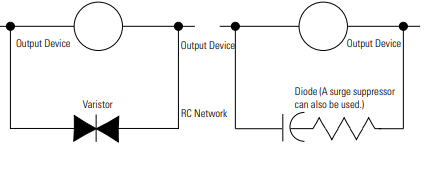
The following diagram shows an output with a suppression device. We recommend that you
locate the suppression device as close as possible to the load device.
If you connect a micro controller FET output to an inductive load, we recommend that you
use an 1N4004 diode for surge suppression, as shown in the illustration on page 17.
Suitable surge suppression methods for inductive load devices include a varistor, an RC
network, or, for dc loads, a diode. These components must be appropriately rated to suppress
the switching transient characteristic of the particular inductive device. See the table on
page 18 for recommended suppressors.
As the following diagram illustrates, these surge suppression circuits connect directly across
the load device. This reduces arcing and damage of the output contacts. (High transients can
cause arcing that occurs when switching off an inductive device.)
If you connect a micro controller triac output to control an inductive load, we recommend
that you use varistors to suppress noise. Choose a varistor that is appropriate for the
application. The suppressors we recommend for triac outputs when switching 120V ac
inductive loads are a Harris MOV, part number V175 LA10A, or an Allen-Bradley MOV,
catalog number 599-K04 or 599-KA04. Consult the varistor manufacturer's data sheet when
selecting a varistor for your application.
For inductive dc load devices, a diode is suitable. A 1N4004 diode is acceptable for most
applications. A surge suppressor can also be used. See the table on page 18 for
recommended suppressors.
Surge Suppression for Inductive ac Load Device
Minimizing Electrical Noise on Analog Controllers
Inputs on analog controllers employ digital high-frequency filters that significantly reduce the
effects of electrical noise on input signals. However, because of the variety of applications and
environments where analog controllers are installed and operated, it is impossible to ensure
that all environmental noise will be removed by the input filters.
Several specific steps can be taken to help reduce the effects of environmental noise on
analog signals:
• install the MicroLogix 1000 system in a properly rated (i.e., NEMA) enclosure. Make
sure that the MicroLogix 1000 system is properly grounded.
• use Belden cable #8761 for wiring the analog channels, making sure that the drain
wire and foil shield are properly earth grounded.
• route the Belden cable separate from any ac wiring. Additional noise immunity can be
obtained by routing the cables in grounded conduit.
Grounding Your Analog Cable
Use shielded communication
cable (Belden #8761). The Belden
cable has two signal wires (black
and clear), one drain wire, and a
foil shield. The drain wire and foil
shield must be grounded at one
end of the cable. Do not ground
the drain wire and foil shield at
both ends of the cable.
Specifications
Environmental Specifications (all MicroLogix controllers)
Description Specification
Operating Temperature 0°C to +55°C (+32°F to +131°F) for horizontal mounting
0°C to +40°C (+32°F to +104°F) for vertical mounting(1
-
 Hirschmann RS20-1600M2T1SDAEHH03.1.02 Rail Switch
 -
 Hirschmann BRS30-24TX Industrial Rail Switch
 -
 Hirschmann RSPM20-4T14T1EV9HHS999.9.99 Managed Ethernet Switch
 -
 Hirschmann BELDEN RS40-0009CCCCSDAPHH09.0.14 / RS400009CCCCSDAPHH09014
 -
Hirschmann RS40 Rail Switch RS40-0009CCCCSDAE
-
 Hirschmann BELDEN RS30-0802T1T1SDAP / RS300802T1T1SDAP Fully Managed Layer 2 Compact Rail Switch
 -
 Hirschmann BELDEN RS20-0800M2M2SDAUHH / RS200800M2M2SDAUHH
 -
 Hirschmann EAGLE30-04022O6TT999SCCY9HSE3F Industrial Firewall Router Switch
 -
 Hirschmann RS20-1600T1T1SDAEHH09.0.14 RS20 Rail Mount Ethernet Switch
 -
 Hirschmann EAGLE0200T1T1TDDY90000HHE05.3.03 Industrial Security Router
 -
Hirschmann - BELDEN MIPP-AD-1L9P
-
 HIRSCHMANN RSPM20-4Z64Z6TV9HHS9 942 106-999 RAIL SAFETY SWITCH
 -
 HIRSCHMANN FIBEROPTIC MODULE FIP P/N: OZDFIPG3T
 -
 HIRSCHMANN RS20-1600M2M2SDAUHH Ethernet rack-mounted switch
 -
 HIRSCHMANN BELDEN RS20-0400T1T1SDAEHH04.0.01 / RS200400T1T1SDAEHH04001
 -
HIRSCHMANN MM2-4FXM3 MICE Media Module
-
HIRSCHMANN RS20-0800M2M2SDAE Industrial Ethernet Rail Switch
-
 Hirschmann RS20-2400T1T1SDAP / RS20-2400T1T1SDAPHH05.0.02
 -
 GE MLJ1005B010H00C MLJ Digital Synchromism Check
 -
 ALSTOM MICROTECH DX21-M2 Digital Excitation Controller
 -
HIRSCHMANN BRS20-1200ZZZZ-STCY99HHSES
-
 HIRSCHMANN MM3-4FXM2 MICE Media Module
 -
Hirschmann RSB20-0800T1T1SAABHH 8Port ENet Rail Switch RSB20
-
 Hirschmann MACH102-8TP Ethernet Switch
 -
 SAACKE DDZ-M marine steam pressure atomizer
 -
 SAACKE SKV-A marine rotary cup atomizer
 -
 SAACKE Seavis HMI05e
 -
 Kollmorgen MMC-SD-2.0-230 Servo Drive 100-240VAC 2KW 10A Output 3PH 100-240VAC
 -
 Kollmorgen Servo drive CR10550
 -
 Kollmorgen AKD-P01207-NACN-0054 Servo Driver
 -
 Kollmorgen S406M-CA-036 Servostar
 -
.png) Kollmorgen AKD-B02407-NAAN-0000 Digital Servo Drive
Kollmorgen AKD-B02407-NAAN-0000 Digital Servo Drive -
 Kollmorgen SERVOSTAR S406AM-CA Digital Servo Drive
 -
 KOLLMORGEN SERVOSTAR 603-AS SERVO AMPLIFIER_SERVOSTAR603AS_S60301
 -
Kollmorgen S700 Servo Controller (S70602-NANANA-NA)
-
 Kollmorgen MPK411 controller
 -
 KOLLMORGEN MMC-SD-1.3-460-D Smart Drive
 -
 KOLLMORGEN AKM21C-CKB2AA-00 / AKM21CCKB2AA00 Servomotor
 -
 BECKHOFF AX5106-0000-0200 | Digital Compact Servo Drives 1-channel
 -
 BECKHOFF C3620-0000 INDUSTRIAL COMPUTER (MOTORSHELVES)
 -
 Beckhoff EK1960-0000 TwinSAFE Compact Controller
 -
 Beckhoff C6930-0050 Control Cabinet Industrial PC
 -
 Beckhoff CP7711-0001-0030 Industrial Computer Detection
 -
 Beckhoff CX1001-0111 Embedded PC CPU Module
 -
 Beckhoff C6017-0020 | Ultra-compact Industrial PC
 -
 Beckhoff EK1322 | 2-port EtherCAT P junction with feed-in
 -
 Beckhoff CP2219-0010 Panel
 -
 BECKHOFF C6015-0020 ULTRA COMPACT INDUSTRIAL PC
 -
 BECKHOFF CX2030-0120/Standard CPU Module Embedded PC Windows PLC controller
 -
 Beckhoff CP7721-1090-0020 Panel PC
 -
 Beckhoff PC CPU Module CX5130-0175
 -
 Beckhoff C6920-0050 Control Cabinet
 -
 Beckhoff EL6631 EtherCAT 2-Port Communication Interface, Profinet RT Controller
 -
 Beckhoff CP6202-0001-0060 touch screen panel PC
 -
 Beckhoff CP3916-1002-0000 Multi-Touch Control Panel
 -
 Beckhoff EP1809-0021 | EtherCAT Box, 16-channel digital input, 24 V DC, 3 ms, M8Preferred type
 -
 Beckhoff CX8190 PLC Embedded Industrial PC Ethernet Controller
 -
 Beckhoff CX2100-0914 Power Supply for External
 -
 Beckhoff Automation CP6906-0001-0000 HMI
 -
 Beckhoff EP7342-0002 Module
 -
 Beckhoff CX1020-0112 / CX1100-0910 / CX1020-N010 / CX1100-0003 Windows CPU
 -
 Beckhoff EP7211-0034 EtherCAT Box 1 Channel Motion Interface
 -
 Beckhoff C6240-0030 Control cabinet Industrial PC
 -
 beckhoff motherboard CB1052-0004 CB1052-0004
 -
 Beckhoff AX2006-AS Servo Drive / Variable Frequency Drive
 -
BECKHOFF CP6207-0001-0020 NSMP
-
 Beckhoff C6930-1142-0060 Industrial Computer
 -
 Beckhoff FC7501-0000 interface card
 -
 Beckhoff CX5140-0175 Embedded PC PLC CPU CX5140 Industrial Controller
 -
 Beckhoff CP7802-1100-0010: High-End IP65 Control Panel with DVI/USB Extended Interface
 -
BECKHOFF CP3716-1058-0010 CONTROL PANEL
-
 Beckhoff AX8108-0000 Single-Axis Module
 -
 Beckhoff CU8851-0000 | USB extension, USB Extended 2.0 receiver box
 -
Beckhoff C6017-0030 | Ultra-compact Industrial PC
-
 Beckhoff CX1001-0120/CX10010120.cx1000-n001.cx1000-n000 System Overview
 -
 Beckhoff CPU Module CX5140-0155/4GB CPU Module
 -
 Beckhoff CP6533-0001-005: Built-in Panel PC with High-Definition Multi-Touch Control
 -
 Beckhoff EL5042 | EtherCAT Terminal, 2-channel encoder interface, BiSS® C
 -
 Beckhoff C6920-1080-0040: Premium Control Cabinet Industrial PC
 -
 Beckhoff C6920-0060 | Control cabinet Industrial PC
 -
 Beckhoff Embedded-PC CX5010-1121
 -
 Beckhoff CB3050-0010 Mainboard Motherboard
 -
 Beckhoff PLC module CX1020-0000 Basic CPU module (service phase)
 -
 Beckhoff CP7812-1056-0010 15" Multitouch Display Control Panel
 -
 Beckhoff CX5120-0115 /2GB Controller Module
 -
 Beckhoff CP7201-1000-0000 Industrial Panel PC
 -
 Beckhoff Servo Motor AM8061-0JH1-0000
 -
 BECKHOFF CP6503-0001-0050 Built-in Panel PC
 -
Beckhoff CP3919-0010 Display G190ETN01.2 19" PCT V04. Multi-touch Control Panel
-
 Beckhoff CX5110-0112-9020/000368201 Embedded PC Intel Atom Processor
 -
 Beckhoff AX8206-0000 Dual-Axis Module
 -
Beckhoff Nail Operating Terminal CP7032-1031-0010
-
Beckhoff AM8042-0EH1-0000 Servomotor 4.10 Nm (M0), F4 (87 mm)
-
 Beckhoff EK9300 Beckhoff CPU Module
 -
Beckhoff CP3224-0020 Multitouch-Panel-PC
-
 Beckhoff CP2712-0000 12.1" 24VDC Touch Screen WMD0
 -
 BECKHOFF CX5240-0195 / 0000289234 Embedded PC 40 GB CFast Card
 -
 Beckhoff CP6932-1000-0000 Control Panel
 -
 BECKHOFF CX5120-0121 PLC Module
 -
 Beckhoff EL3218 | EtherCAT Terminal, 8-channel analog input
 -
Beckhoff C6640-0050 | Control cabinet Industrial PC
-
 Beckhoff Cx5130-0120/4GB Embedded-PC
 -
 BECKHOFF CX2030-0122 PLC PROCESSOR
 -
 BECKHOFF CX5020-0122 Controller Module
 -
 Beckhoff CP3915-0000 Multitouch Panel
 -
 BECKHOFF EL3014 | EtherCAT Terminal
 -
 BECKHOFF Industrial Computer c6920-1057-0030
 -
 Beckhoff CX5130-0141/4GB CX5130-0141 Embedded PC
 -
 Beckhoff C6240-1052-0040 4-086-06-3073 Industrial Computer
 -
 Beckhoff CX5140-0135 /4GB High-Performance Embedded Industrial PC
 -
 Beckhoff C6515-1001-0000 Industrial PC
 -
 Beckhoff AX5103-0000-0200 - Digital Compact Servo Drives
 -
 Beckhoff CX2030-0130-1003/4GB Basic CPU module
 -
 Beckhoff AX8620-0000 Power Supply Module
 -
 Beckhoff CX9020-0111 module with
 -
 Beckhoff EL7332 PLC Module
 -
 BECKHOFF CP7709-0001-0020 HMI
 -
 Beckhoff CX5120-0155/2GB Embedded PC
 -
 BECKHOFF CP7037-1037-0010 OPERATOR INTERFACE TOUCHSCREEN
 -
 Beckhoff EK9000 | ModbusTCP/UDP Bus Coupler
 -
 Beckhoff Touch Panel Screen CP6020 -0000-0000
 -
 Beckhoff CX2020-0121 Module FAST Shipping
 -
 Beckhoff CX2030-0125 Basic CPU Module
 -
 Beckhoff CP3918-0000 Multi-Touch 18.5" Control Panel
 -
 Automotion LC4A00010 DC BL Motor Control, ATS, Sub Assy, SCP, 115VAC,
 -
 500T-115VAC - VAS ENGINEERING - DORIC 500 SERIES DIGITAL TEMP INDICATOR
 -
 Honeywell X-DCS2000/EN Digital Integrated System Manager 50/60Hz 100-240V #4
 -
 Kollmorgen S60600 Servostar600 606-Fan 4 kVA, 6 A, 3 X 230 - 480 V


