
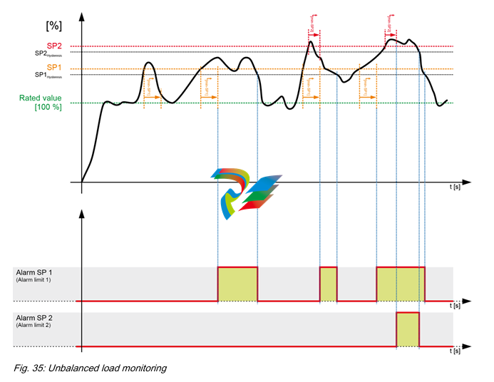
EMERSONDeltaV SISTM Logic Solver
proof test automatically. A warning is given to the operator
before the automatic proof test is started.
Sequence of Events Capability
With DeltaV SIS, events are automatically generated as
function blocks are executed within a module scan. Events
are time stamped with a resolution of <1 ms, and they are
recorded in the sequence that they occur in the Event
Chronicle. When using standard function blocks such as
input blocks, voter blocks, and cause and effect blocks, a
standard set of events are automatically generated without
special configuration or programing required. For example,
I/O failures, trip limits, first outs, and other similar events
are automatically time stamped by function blocks and
recorded in the Event Chronicle. When a process variable
exceeds the trip limit, DeltaV SIS records the event along
with the analog value and the trip condition.
In general, when there is a plant event that triggers an
emergency shutdown from the SIS, one input will exceed
a trip limit on one scan and this will cause outputs to trip
and more inputs will then change state. Sequence of
Events Recording has been used to find that first input that
caused the trip by looking at all of the inputs in the plant.
With the DeltaV SIS system, the operator simply filters the
Event Chronicle for first out trips, and the first-out is clearly
visible.
If higher resolution is required for some channels then
they can be wired to both the DeltaV SIS Logic Solver and
also to a DeltaV Discrete Input Card for Sequence of
Events, which provides a resolution of 0.25 ms.
DeltaV SIS Product Data Sheet
May 2013 – Page 6 DeltaV SIS Logic Solver
System Compatibility
DeltaV SLS 1508 Specifications
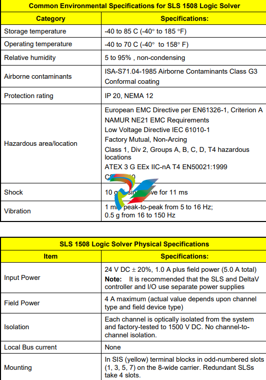
SLS 1508 Logic Solver Weight, Heat Generation and Power Consumption
Item Specifications:
Redundant Logic Solver
Weight – 1.20 kg
Heat Dissipation – 24 W
Power – 2 A @ 24 V DC + Dig out Field Loads
DeltaV SIS Product Data Sheet
May 2013 – Page 8 DeltaV SIS Logic Solver
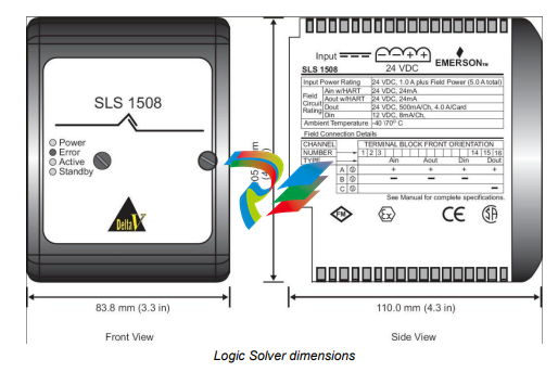
Channel Specifications
The Logic Solver provides 16 channels of flexible I/O, meaning that each channel can be configured as an Analog Input
(HART), HART Two-State Output, Discrete Input, or Discrete Output channel.
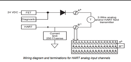
Analog Input Channel Specifications (includes HART)
Item Specifications:
Number of channels 16
Isolation
Each channel is optically isolated from the system
and factory-tested to 1500 V DC. No channel-tochannel isolation.
Nominal signal span 4 to 20 mA
Full signal range 1 to 24 mA
2-wire transmitter power 15.0 V minimum terminal-to-terminal @ 20 mA;
current limited to 24 mA max
Safety / diagnostic accuracy 2.0% of span
Resolution 16 bits
Filtering
2-pole, corner frequency 5.68 Hz
-3 dB at 5.68 Hz
-20.0 dB at 40 Hz (half the sample rate)
-
 MOTOROLA MVME172PA-652SE VME Embedded Controller
 -
 MOTOROLA FLN4234A ACE3600 CPU3680 Processor Module
 -
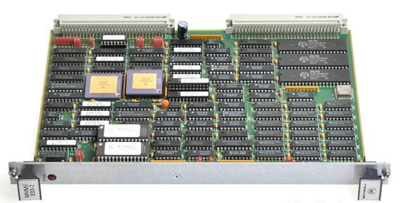 Motorola MVME333-2 Controller Communications Module Specs
 -
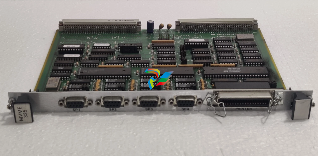 MOTOROLA MVME335 PCB California VME Module 0733500
 -
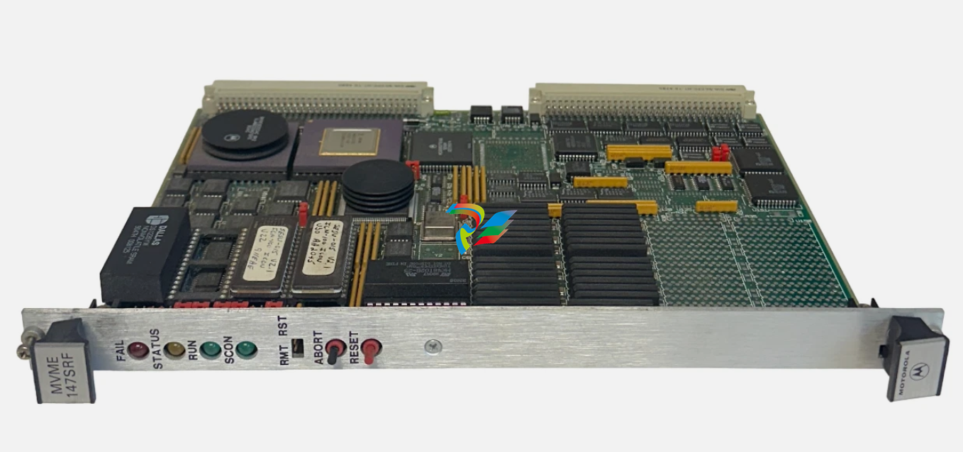 EMERSON MOTOROLA MVME-147SRF / MVME147SRF MPU VME MODULE
 -
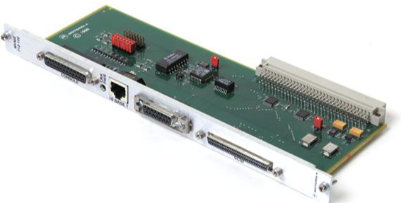
 MOTOROLA MVME705A Serial Transition Module
 -
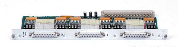 MOTOROLA MVME705B 6-Channel Serial Transition Module
 -
 MOTOROLA MVME712A MVME712AM I/O Transition Module
 -
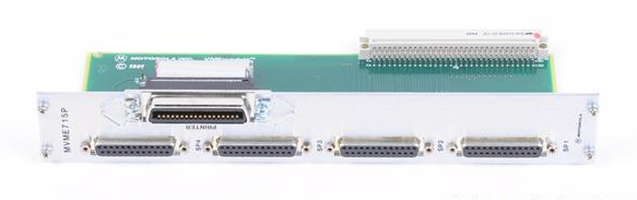 MOTOROLA MVME715P Rear Transition Module
 -
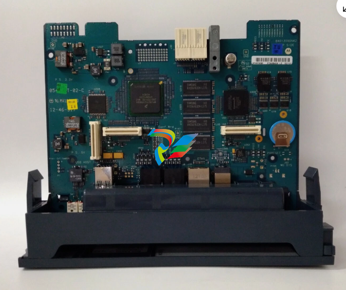
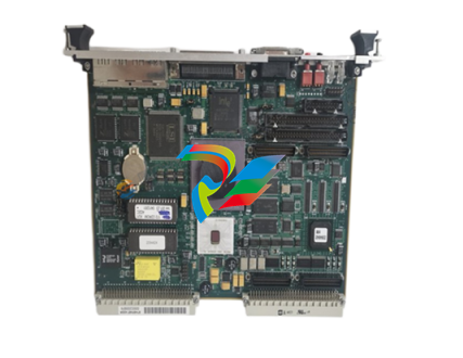
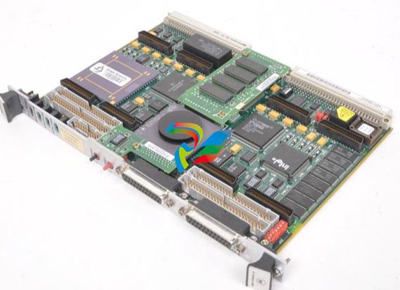
 MOTOROLA MVME172 VME Embedded Controller
 -
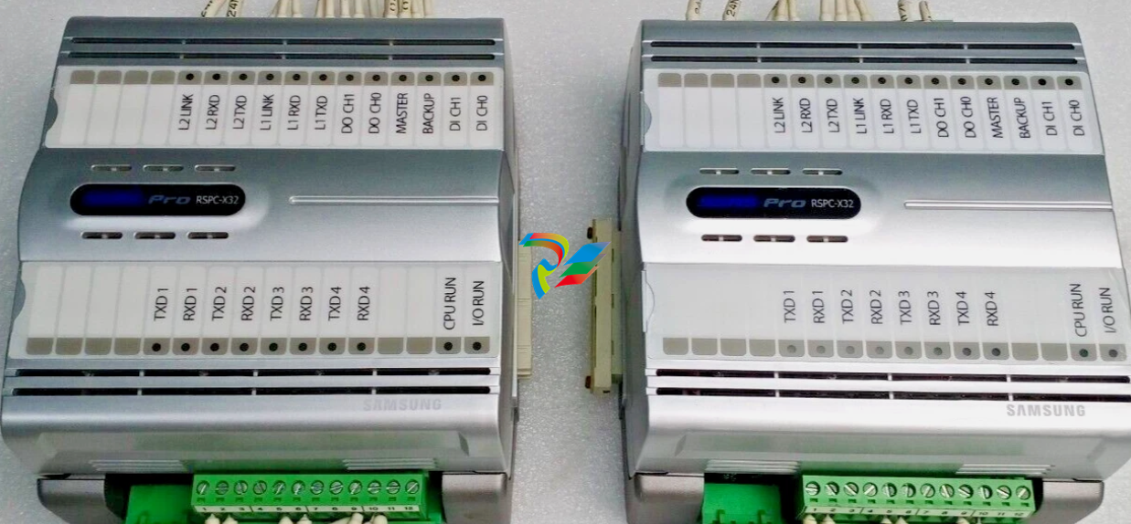 SAMSUNG SSAS-PRO RSPC-X32 ALARM AND MONITORING SYSTEM MODULE
 -
 MOTOROLA TMCP700 W33378F High-Performance Industrial Computing Module
 -
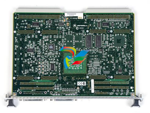
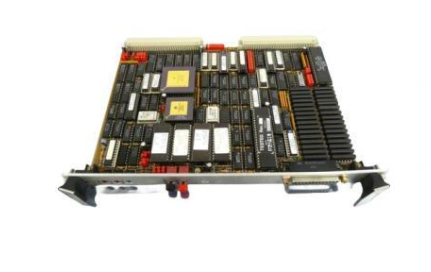
 MOTOROLA VME Single Board Computer MVME188A
 -
 MOTOROLA MVME162PA-344 High-Performance Embedded VME Controller
 -
 MOTOROLA FAB 0340-1049 High-Efficiency Intelligent Embedded Module
 -
 MOTOROLA 30-W2960B01A High-Performance Industrial Interface Module
 -
 MOTOROLA MVME712M Transition Module.
 -
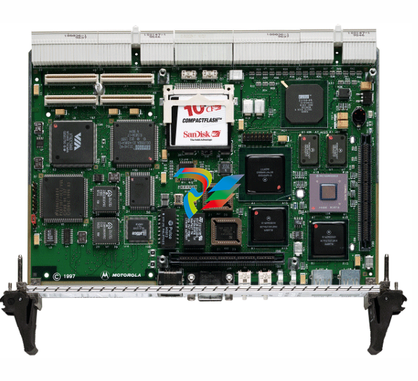
 MOTOROLA MVME5500 Series VME Single-Board
 -
 MOTOROLA MVME300 High-Reliability GPIB VMEbus Controller
 -
 MOTOROLA CPCI-6020TM High-Performance CompactPCI Transition Module
 -
 MOTOROLA MVME162-210 Embedded Controller
 -
 MOTOROLA MVME162-522A 01-W3960B/61C Embedded Controller
 -
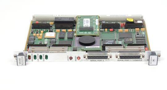
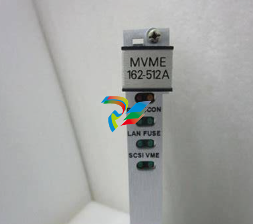 MOTOROLA MVME162-512A Embedded Controller
 -
 MOTOROLA MVME162-512 Embedded Controller
 -
 MOTOROLA MVME162-220 Embedded Controller
 -
 MOTOROLA MVME162-13 Embedded Controller
 -
 MOTOROLA MVME162-10 Embedded Controller
 -
 MOTOROLA MVME162-012 Embedded Controller
 -
 MOTOROLA MCP750 CompactPCI Host Slot Processor
 -
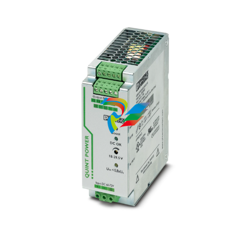
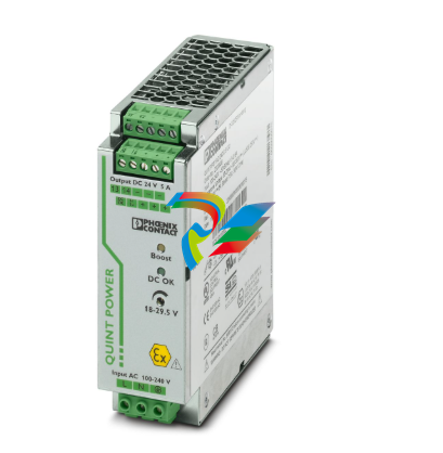
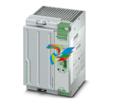 Phoenix 2320267 QUINT-UPS/ 24DC/ 24DC/10/3.4AH - Uninterruptible power supply
 -
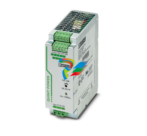
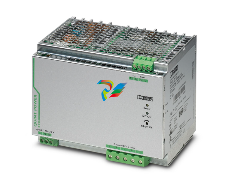
 Phoenix QUINT4-PS/3AC/24DC/40 - Power supply 2904623
 -
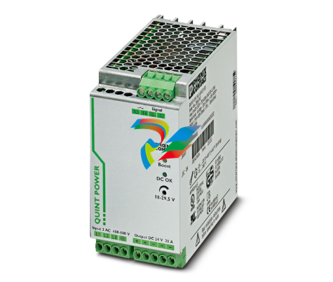
 Phoenix 2904622 QUINT4-PS/3AC/24DC/20 - Power supply
 -
 Phoenix 2905012 QUINT-PS/96-110DC/24DC/10/CO - DC/DC converter, protective coating
 -
 Phoenix 2905011 QUINT-PS/60-72DC/24DC/10/CO - DC/DC converter, protective coating
 -
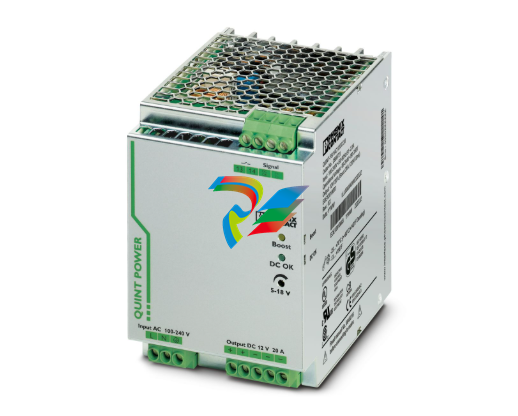
 Phoenix 2904600 QUINT4-PS/1AC/24DC/5 - Power supply
 -
 Phoenix 2904603 QUINT4-PS/1AC/24DC/40 - Power supply
 -
 Phoenix 2904601 QUINT4-PS/1AC/24DC/10 - Power supply
 -
 Phoenix 2904602 QUINT4-PS/1AC/24DC/20 - Power supply
 -
 Phoenix QUINT-PS/60-72DC/24DC/10 - DC/DC converter 2905009
 -
 Phoenix QUINT-PS/96-110DC/24DC/10 - DC/DC converter 2905010
 -
 Phoenix QUINT-PS/3AC/24DC/20/CO - Power supply, with protective coating 2320924
 -
 Phoenix QUINT-PS/1AC/12DC/20 - Power supply 2866721
 -
 Phoenix 2320908 QUINT-PS/1AC/24DC/ 5/CO - Power supply, with protective coating
 -
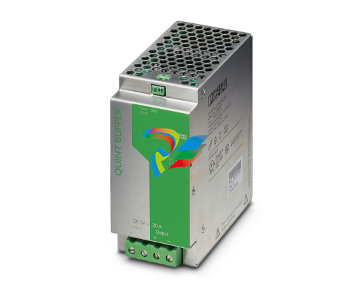 Phoenix 2866213 QUINT-BUFFER/24DC/20 - Buffer module
 -
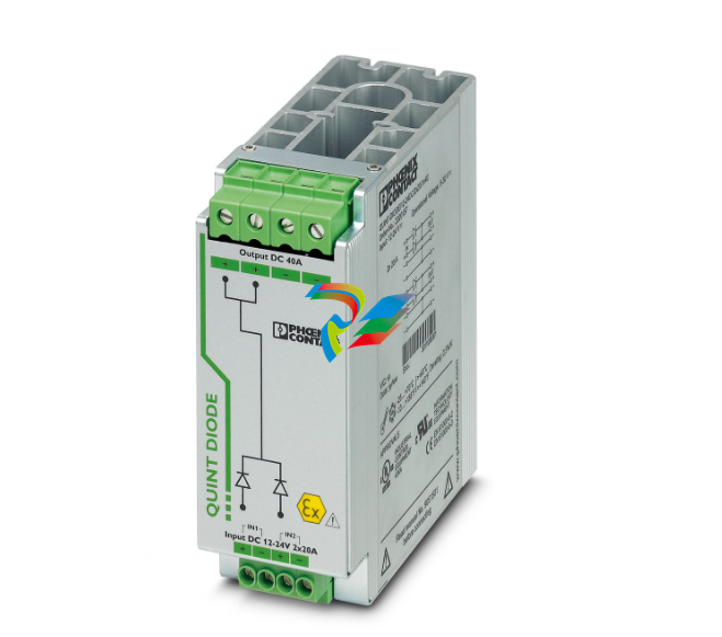
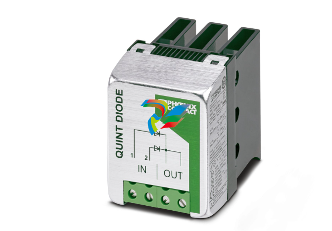 Phoenix 2866585 QUINT-DIODE/48DC/40 - Redundancy module, with protective coating
 -
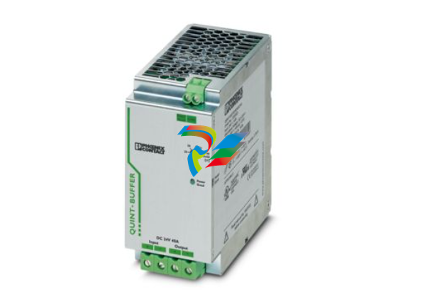 Phoenix 2320393 QUINT-BUFFER/24DC/24DC/40 - Buffer module
 -
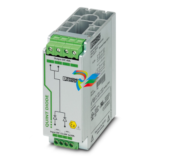 Phoenix 2320157 QUINT-DIODE/12-24DC/2X20/1X40 - Redundancy module
 -
 Phoenix 2907720 QUINT4-DIODE/48DC/2X20/1X40 - Redundancy module
 -
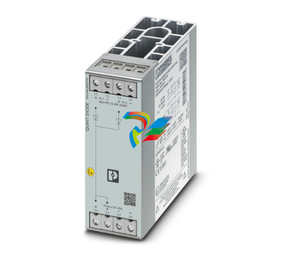 Phoenix 2907719 QUINT4-DIODE/12-24DC/2X20/1X40 - Redundancy module
 -
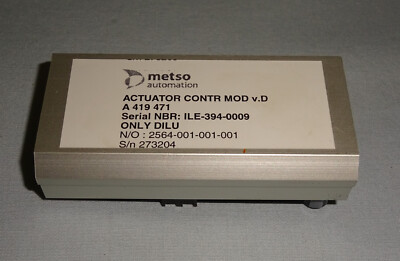 Metso A419471 High-Performance Analog Output Module
 -
 Applied Materials (AMAT) 0190-19092: High-Performance RF Match Controller Board
 -
 ABB UFC789AE101 3BHE014023R0101 High-Performance AC 800PEC Control Unit
 -
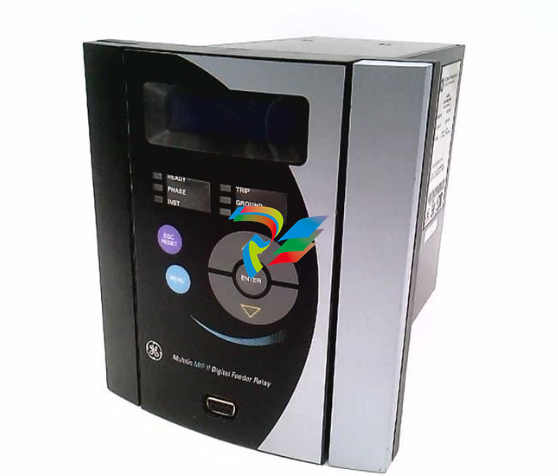 GE MIFIIPA55E20HI00 Multilin MIF II Digital Feeder Protection Relay
 -
 GE DS3815PAHB1A1A Speedtronic Mark IV Processor & Interface Board
 -
 GE DS3800NB1A Speedtronic Mark IV Power Supply / Regulator Board
 -
 GE DS3800HIOC Speedtronic Mark IV High-Level Input/Output Board
 -
 GE DS3800NHVG Speedtronic Mark IV High-Voltage Gate Driver Board
 -
 ABB 1TGE120011R1010 MC M117 KIT 24VDC CMMB+PTC
 -
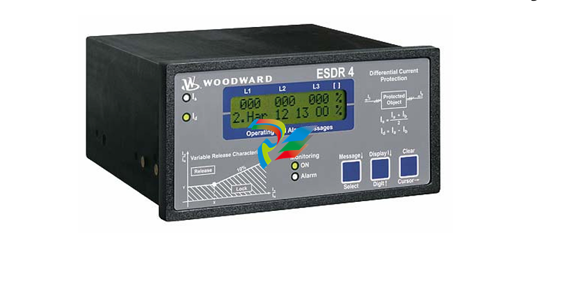 Woodward 5448-897 Current Differential Protection Relay
 -
 GE IS220PAOCH1BE Mark VIe Analog I/O Module
 -
 GE IS220PDOAH1B Mark VIe Discrete Output (PDOA) I/O Pack
 -
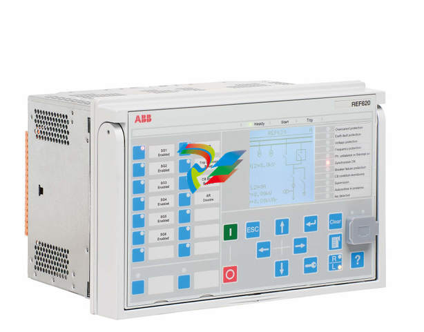 ABB Feeder Protection and Control REF620E_1G NBFNAAAAAABC6BBN11G
 -
 ABB MT-91-ARCFPA High-Precision Tension Control Interface Module
 -
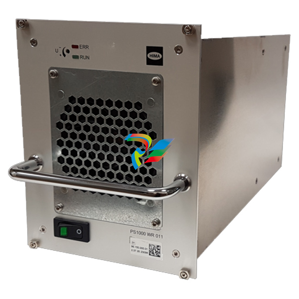 HIMA PS1000/230010 982200080 high-performance power supply module
 -
 HIMA H7202 Distribution Fuse Board / Infeed Board
 -
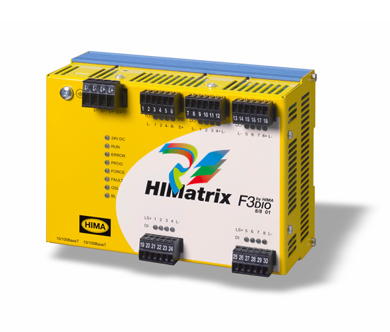
 HIMA F60DIO24/1601 Safety-Related Controller
 -
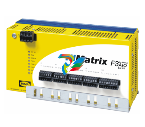
 HIMA F60DO801 Safety-Related Controller
 -
 HIMA H7201 Line fuse board
 -
 HIMA HIMatrix ELOP II 892042336 Version V5.6 Build 1501.9810 IV1
 -
HIMA HIMatrix SILworX 504110 895400001
-
 HIMA HIMatrix SILworX 504111 895210001
 -
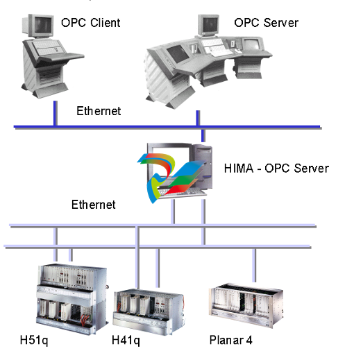 HIMA OPC DA Server 892042400 Version 3.56.4
 -
 HIMA OPC Alarm & Event Server (892042420) Version 4.1.3
 -
 HIMA OPC Alarm & Event Server (892042420) Version 4.0.5
 -
 Phoenix QUINT-DIODE/12-24DC/2x20/1x40 2320157 Redundancy module
 -
 Phoenix QUINT-PS/1AC/24DC/40 2866789 Power supply
 -
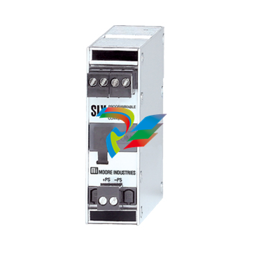 Moore SIY/PRG/4-20MA/10-42DC SIY PC Programmable Signal Isolator and Converter
 -
.png) Motorola 01-W3394F-03F Communication Interface Module
Motorola 01-W3394F-03F Communication Interface Module -
 Motorola AP-4 256 MByte 01-W3839F-07A Communication Module
 -
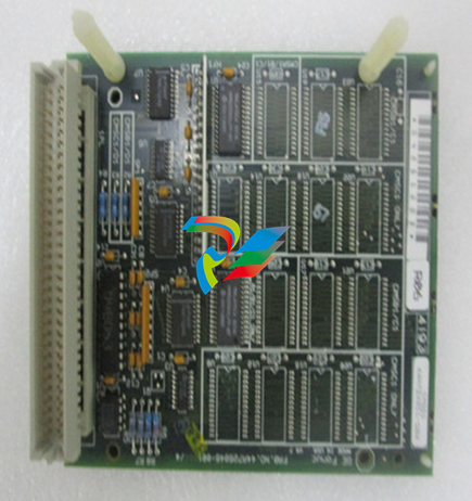
MOTOROLA MVME2432 01-W3394F-03C VME Processor Module
-
 MOTOROLA PCE I 01-W3839F-07A VME Processor Module
 -
.png) Motorola HPR431 / SYS431 / SYS443 / MFT543 Component Assembly
Motorola HPR431 / SYS431 / SYS443 / MFT543 Component Assembly -
Motorola AP-4 01-W3394F-03G Communication Interface Module
-
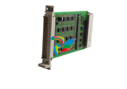
 Emerson 01-W3878F-02D DeltaV M-Series I/O Module
 -
 ICS Triplex Trusted T8232 Power Pack Module
 -
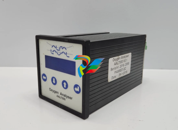 ALFA LAVAL AAL7000 OXYGEN ANALYSER V0.1
 -
Alstom MPM123 Measurement and Protection Module
-
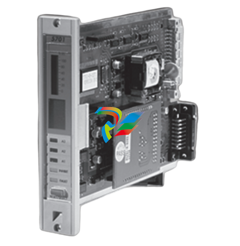 Honeywell 5701 CONTROL SYSTEM
 -
.png) KONGSBERG MRU-E-JB1 Host machine
KONGSBERG MRU-E-JB1 Host machine -
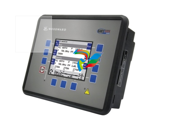 Woodward easYgen-3200-1/P1 8440-2049
 -
 Woodward easYPROTEC-1410-7 8441-1161 8441-1160
 -
 Woodward MFR300-71M/K45 8444-1111 8444-1112
 -
 Woodward MFR300-75M 8444-1107 8444-1108 8444-1109
 -
 Woodward MFR300-71M/K42 8444-1104
 -
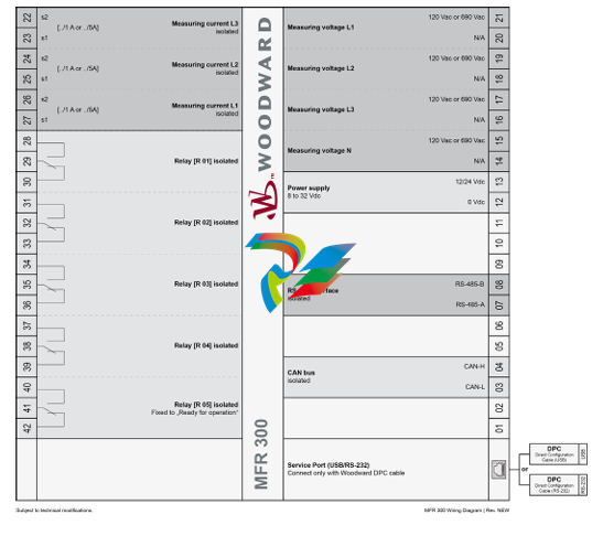
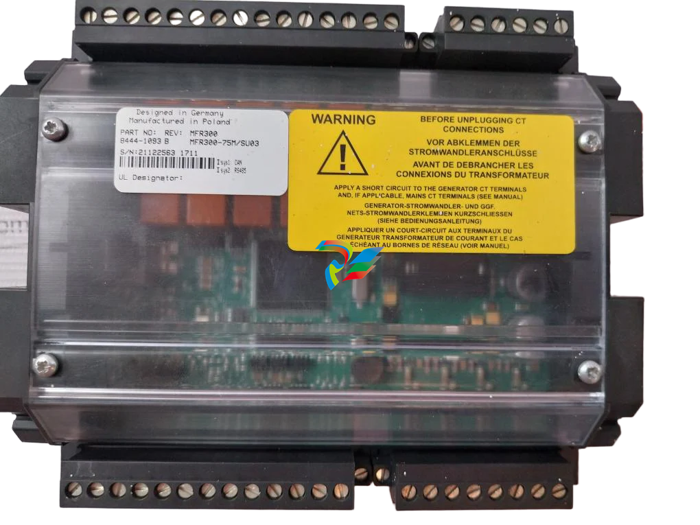 Woodward MFR300 75M/SU03, Transducer 8444-1093 8444-1094 8444-1095
 -
 Woodward MFR300-71M 8444-1091 8444-1092
 -
Woodward MFR300-15M 8444-1090 8444-1089
-
 Woodward MFR300-11M 8444-1071 8440-1089
 -
 Woodward MFR500-6M/WK0400 + DPC USB 8444-1070
 -
 Woodward MFR300-15M 8444-1064
 -
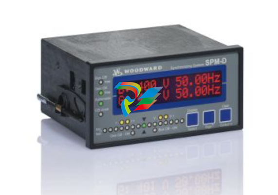
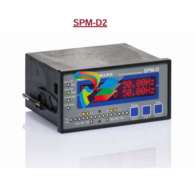
Woodward SPM-D2-1040B/NYB 8440-2189
-
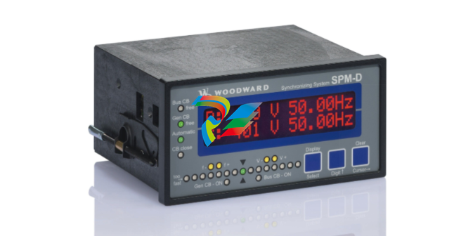
Woodward SPM-D2-1010B/NYB 8440-2177
-
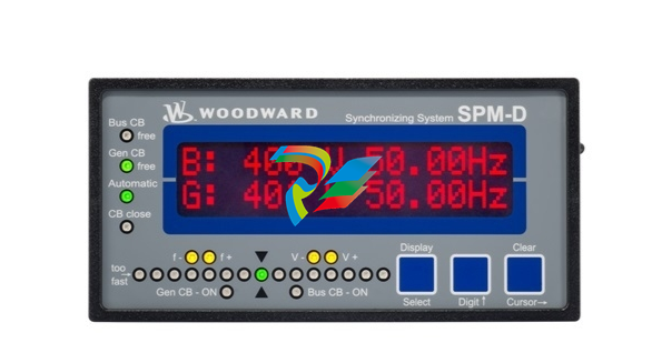
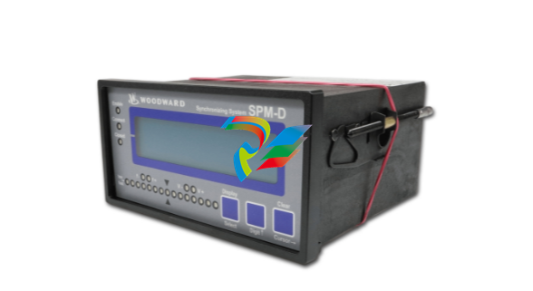 Woodward SPM-D2-10B/PSY5-FU-D 8440-2170
 -
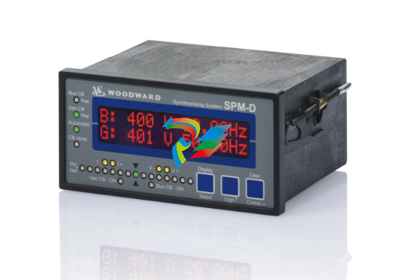
 Woodward SPM-D2-1040B/XN analog speed/voltage bias 8440-2190
 -
Woodward MFR300-71M 8444-1063
-
SPM-D2-1010B/X analog speed/voltage bias 8440-2168
-
 Woodward SPM-D2-1040B/X analog speed/voltage bias 8440-2171
 -
 Woodward SPM-D2-1010B/N wide range power supply 8440-2174
 -
Woodward SPM-D2-1040B/N wide range power supply 8440-2175
-
 Woodward SPM-D2-1010B /110VAC sensing 8440-2166
 -
Woodward SPM-D2-1040B /400VAC sensing 8440-2164
-
 Woodward DTSC-200A 8440-2297
 -
 Woodward DTSC-200-55B/K38 8440-2155
 -
Woodward DTSC-200-51B 8440-1867 8440-1868
-
 Woodward 8445-1049 8445-1048 Converter, 1x FO to CAN
 -
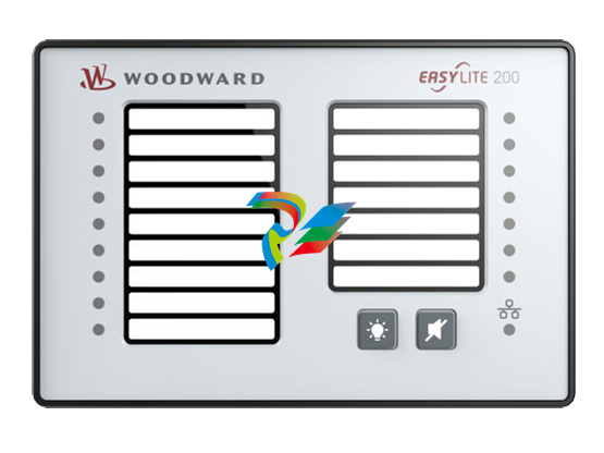 Woodward easYlite-200 8446-1007 LED Lamp Expansion Module
 -
 Woodward IKD-OUT-16 16 DO Expansion Card 8440-2306
 -
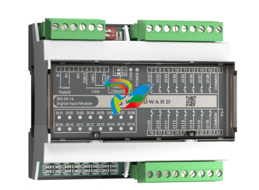 Woodward IKD-IN-16 16 DI Expansion Card 8440-2307
 -
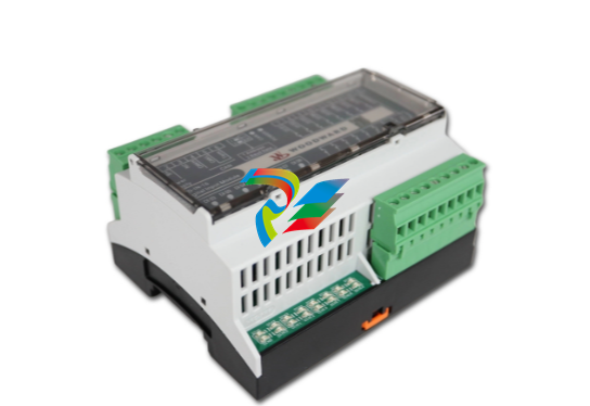
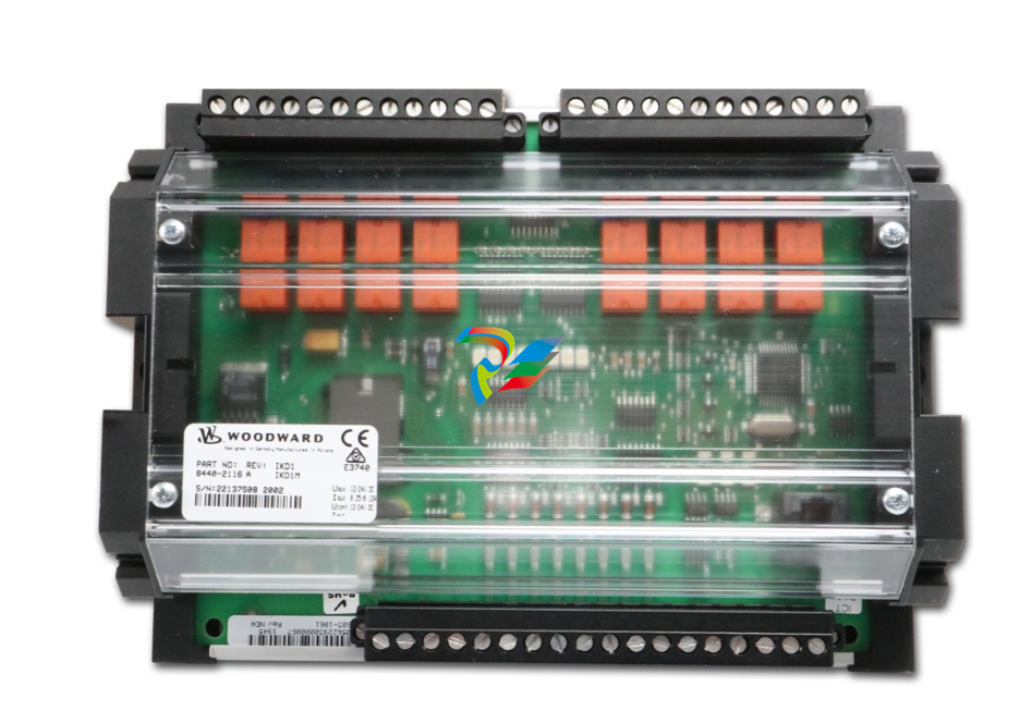 Woodward IKD1M 8 DI/8 DO Expansion Card 8440-2116
 -
 Woodward easYview-07-30 8446-1071
 -
 Woodward easYFLEX-3400XT-P2 (GAP) 8440-2217
 -
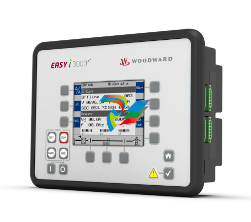
Woodward easY-I-3400XT-P1 8440-2293
-
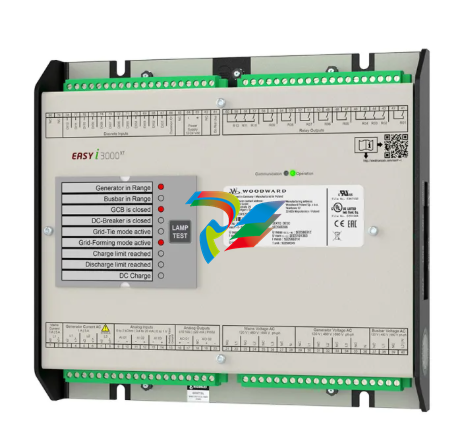 Woodward easY-I-3500XT-P1 8440-2292
 -
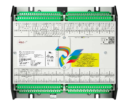 Woodward MSLC-2XT 8440-2298 Master Synchronizer and Load Control
 -
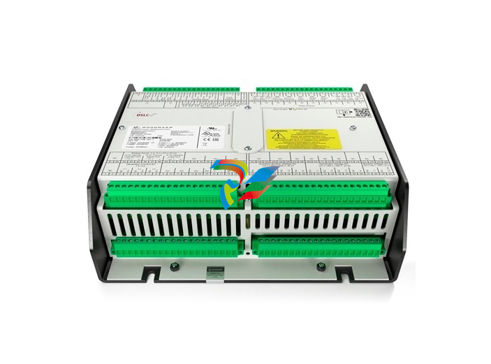 Woodward DSLC-2XT 8440-2299 Digital Synchronizer and Load Control
 -
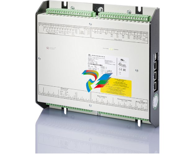 Woodward: GC-3400XT-P1 8440-2267 Group Controller
 -
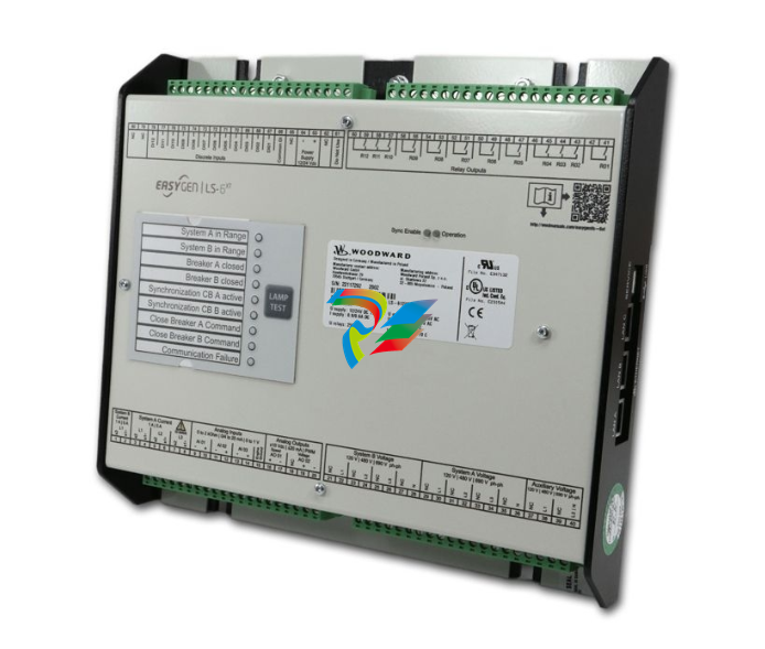 Woodward: LS-612XT-P2 8440-2317
 -
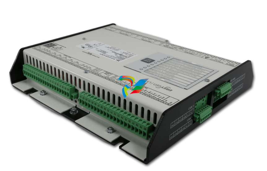 Woodward: CONTROL-LS-612XT-P1,8440-2222 Cabinet back mounting


