
ALSTOM Ethernet Manual
Preface
This document
The Ethernet Manual is the same for all ALSTOM Power Service controllers equipped with Ethernet. Therefore reference to specific controller names such as EPIC or EFFIC will not be used from this point, instead the general term “controller” will be used. This Ethernet Manual contains information for the Designing Engineers on the pre-commissioning of the Ethernet network. It also contains information for Shift Operators on the PC-MTU software, which is a software used for setting up, operating and monitoring an installation of several controllers in the network. The PC-MTU software is linked together with the web pages on the controllers built-in web server. These web pages are the interface used to configure each individual controller. For more information, see Operator’s & Installation Manual.
Related documents
The following documents are related to the Ethernet Manual:
• Ethernet Manual- (this document).
• EPIC/EFFIC Operator’s & Installation Manual - contains information for all groups of users from the installation and commissioning to daily operation and tuning of the cleaning process. -Shift Supervisor Advanced operation and taking action on all alarms that may occur. -Process Engineer From small to medium scale diversions from factory settings in order to optimize the cleaning process. -Commissioning Engineer All stages of the commissioning. -Installation personnel (mechanical and electrical) Mechanical, electrical and communication installation.
ALSTOM Power Service reserves the right to revise any publication and to make changes to its contents, at any time, without obligation to notify any person or entity of such revision or changes. Furthermore, ALSTOM Power Service reserves the right to make changes to any and all parts of hardware and software, at any time, without obligation to notify any person or entity of such changes.
Ethernet standard
Ethernet is a network standard of communication. The most widely used for LAN communication, Ethernet typically runs at 100 megabytes per second. All new controllers developed by ALSTOM Power Service use the Ethernet standard for communication. The following chapter describes what type of equipment is needed to successfully set up a Ethernet network that functions well together with Alstom Power Service products.
General information on Ethernet
For general information on Ethernet there is a lot of information available both on the Internet and in published books. A good place to start is one of the following websites:
• Cisco Internetworking Technology Overview for Ethernet
• Howstuffworks http://computer.howstuffworks.com/ethernet.htm For specific information on Industrial Ethernet standards the Industrial Ethernet Planning and Installation Guide is recommended, can be down loaded from the following website
Typical Ethernet network
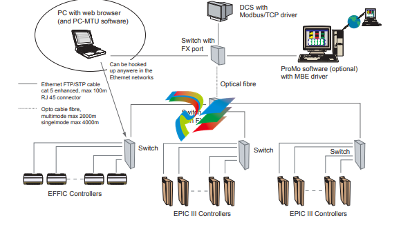
Ethernet switch
The Ethernet switch shall meet the following standards:
• EMC immunity for industry EN 50082-2 or EN 61000-6-2 Alstom Power Service has successfully used the switches from HMS Industrial Networks, Sweden and different types of switches from Hirschman Electronics.
Ethernet hub
Ethernet hub should not be used in a new installation, because it will decrease the performance of the network. With a hub in the network it is also more difficult to calculate the allowed cable lengths.
Connection to controller
The Ethernet board connection on the controller is of the following type:
• RJ45 10/100M/bit auto negotiation
Cables
Cat 5E FTP cables with RJ45 connectors are recommended for the Ethernet network.
Ethernet ports and protocols
The following Ethernet ports are used:
• Port 20, 21 for FTP • Port 80 for HTTP
• Port 502 for Modbus/TCP data
• Port 3 250 for PC-MTU - IP config
• Port 49 200, 49 201 for the master functionality and PC-MTU.
Ethernet routers
Routers should not be installed in the EPIC III Ethernet network. The PCMTU and master functionality will not function properly through it.Setup Ethernet network
The following chapter describes how to install the software and how to setup your Ethernet network. The installation procedure is the same for all ALSTOM Power Service controllers equipped with Ethernet. Therefore reference to specific controller names such as EPIC or EFFIC will not b
Software installation
1. Insert the PC-MTU software CD into your CD-ROM drive. 2. Follow the installation instructions.
System requirements
System requirements
• PC with 300 megahertz or higher processor clock speed recommended.
• Intel Pentium/Celeron family, or AMD K6/Athlon/Duron family, or compatible processor recommended.
• 128 megabytes (MB) of RAM or higher recommended.
• Super VGA (1024 x 768) or higher-resolution video adapter and monitor. • CD-ROM or DVD drive.
• Keyboard and Microsoft Mouse or compatible pointing device.
• Microsoft Windows® 2000 or Microsoft Windows XP®
• Microsoft Internet Explorer® 6.0 or higher.
-
 CTI 2500C-RBC-RS485 RS485 Remote Base Controller
 -
 CTI 2500C-RBC-PRF Profibus Remote Base Controller
 -
 CTI 2500C-PS-24V-35 35-Watt DC Power Supply
 -
 CTI 2500C-PS-120V-35 35-Watt AC Power Supply
 -
 CTI 2500C-R8 Eight-Slot Base
 -
 CTI 2500C-R4 Four-Slot Base
 -
 CTI 2500C-R16 Sixteen-Slot Base
 -
 CTI 2500C-2572-B Fast Ethernet TCP/IP Adapter
 -
 CTI 2500C-J750 Compact Janus PAC with 3MB Project Memory
 -
 CTI 2500C-C300 CPU with 512K User Memory
 -
 CTI 2500C-C200 CPU with 256K User Memory
 -
 CTI 2500C-C100 CPU with 128K User Memory
 -
 CTI 2500C-8-AO 8 Analog Outputs
 -
 CTI 2500C-8-AI 8 Analog Inputs
 -
 CTI 2559-FCAL Precision Calibration Connector
 -
 CTI 2559-FPC 40-Position Screw-Terminal Connector
 -
 CTI 2500-RFC PLC to RF Modem Cable
 -
 CTI 2500-40F 40-Position Standard Screw-Terminal Connector
 -
 CTI 2505 Vibration Sensor Interface Module
 -
 CTI 2554-A 4-Channel Isolated High Speed Counter Module
 -
 CTI 2553-A 2-Channel Mag Meter Input Module
 -
 CTI 2502 2-Channel High Speed Counter Input Module
 -
 CTI 2559-TC 8-Channel Thermocouple Input Module
 -
 CTI 2556-A 16-Channel Isolated Thermocouple Input Module
 -
 CTI 2556 16-Channel Isolated Thermocouple Input Module
 -
 CTI 2551-A 8-Channel Isolated Thermocouple Input Module
 -
 CTI 2559-RTD 8-Channel RTD Input Module
 -
 CTI 2557-A 16-Channel RTD Input Module
 -
 CTI 2557 16-Channel RTD Input Module
 -
 CTI 2552-A 8-Channel Isolated RTD Input Module
 -
 CTI 2534 8-Point Form-C Relay Output Module
 -
 CTI 2532 16-Point Form-A Relay Output Module
 -
 CTI 2531 32-Point Form-A Relay Output Module
 -
 CTI 2530 8-Point Form-C Relay Output Module
 -
 CTI 2562 8-Channel Analog Output Module
 -
 CTI 2560-A 8-Channel Isolated Analog Output Module
 -
 CTI 2501 8in/4out Analog Module
 -
 CTI 2558 8-Channel Analog Input Module
 -
 CTI 2555-A 16-Channel Analog Input Module
 -
 CTI 2550-A 8-Channel Isolated Analog Input Module
 -
 CTI 2599 8/16/32-Point AC Output Module
 -
 CTI 2598-8 8-Point AC Output Module
 -
 CTI 2598 8/16-Point AC Output Module
 -
 CTI 2597 8/16/32-Point DC Output Module
 -
 CTI 2596-8 8-Point DC Output Module
 -
 CTI 2596 8/16-Point DC Output Module
 -
 CTI 2595 16-Point TTL/Word Output Module
 -
 CTI 2591-EF 16-Point Isolated 11-146 VDC Output with Front Panel Accessible Fuses
 -
 CTI 2591-A 16-Point Isolated 11-146 VDC Output Module
 -
 CTI 2590-EF 16-Point Isolated 20-132 VAC Output with Front Panel Accessible Fuses
 -
 CTI 2590-A 16-Point Isolated Discrete 20-132 VAC Output Module
 -
 CTI 2589-B 8/16/32-Point Universal Discrete Input Module
 -
 CTI 2589-A 8/16/32-Point Universal Discrete Input Module
 -
 CTI 2588-8 8-Point Universal Discrete Input Module
 -
 CTI 2585 16-Point TTL/Word Input Module
 -
 CTI 2582 16-Point Isolated 125 VDC Input Module
 -
 CTI 2581 16-Point Isolated 12-56 VDC Input Module
 -
 CTI 2580 16-Point Isolated 95-132 VAC Input Module
 -
 CTI 2500-TAP RS485 Network Tap
 -
 CTI 2500-RIO-B RS485 Remote Base Controller
 -
 CTI 2500-RIO-A RS485 Remote Base Controller
 -
 CTI 2500-RBC Profibus Remote Base Controller
 -
 CTI 2515-A 100-Watt AC/DC Power Supply with Redundancy Support
 -
 CTI 2515 100-Watt AC Power Supply (MATURE - replaced by 2515-A)
 -
 CTI 2513-A 75-Watt DC Power Supply with Redundancy Support
 -
 CTI 2513 75-Watt 24VDC Power Supply
 -
 CTI 2512-A 75-Watt AC/DC Power Supply with Redundancy Support
 -
 CTI 2512 75-Watt AC/DC Power Supply
 -
 CTI 2510 125 VDC Power Supply
 -
 CTI 2500-SSB Single Slot Blank Front Panel
 -
 CTI 2500-R11-A Eleven-Slot Redundant Base
 -
 CTI 2500P-R16 Sixteen-Slot Base with High-Speed Channel
 -
 CTI 2500P-R8 Eight-Slot Base with High-Speed Channel
 -
 CTI 2500P-R4 Four-Slot Base with High-Speed Channel
 -
 CTI 2541 Redundant Processor Manager Module
 -
 CTI 2577 Profibus DP Slave Adapter
 -
 CTI 2573-MOD Serial Interface Adapter with MODBUS
 -
 CTI 2572-AF Fast Ethernet TCP/IP Adapter with Optical Fiber Connection
 -
 CTI 2572-A Fast Ethernet TCP/IP Adapter
 -
 CTI 2572 Ethernet TCP/IP Adapter
 -
 CTI 2572-B Fast Ethernet TCP/IP Adapter
 -
 CTI 2576 DeviceNet™ Scanner Module (MATURE)
 -
 CTI 2500P-ECC1 Ethernet Communications Coprocessor
 -
 CTI 2500P-JACP Janus Application Coprocessor
 -
 CTI 2500P-ACP1 Application Coprocessor (MATURE - replaced by 2500P-JACP)
 -
 CTI 2500P-J450 Janus PAC with 2MB Project Memory
 -
 CTI 2500-C400 CPU with 3072K User Memory
 -
 CTI 2500-C300 CPU with 512K User Memory
 -
 CTI 2500-C200 CPU with 256K User Memory
 -
 CTI 2500-C100 CPU with 128K User Memory
 -
 CTI 2500P-J750 Janus PAC with 3MB Project Memory
 -
 Shinkawa WHF3006M Displacement Converter
 -
Shinkawa JBP-220 (P-24-94A / P-24-94B) Circuit Board Module
-
 SHINKAWA WKN-142K5 2-WIRE VIBRATION TRANSDUCER
 -
Shinkawa FRP-321 (P-26-54A / P-26-54B) Circuit Board Module
-
 Shinkawa IOP-160 (P-25-72A / P-25-72B) Circuit Board Module
 -
 Shinkawa PK-147B-1 / PK-147A-1 Circuit Board Module
 -
 Shinkawa CPP-91A Circuit Board Module
 -
 Shinkawa FRP-177 PCB Module
 -
 Shinkawa CPP-127 (P-26-74A / P-26-74B) Circuit Board Module
 -
Shinkawa FRP-227 (P-24-86A / P-24-86B) Circuit Board Module
-
 Shinkawa MDP-104 (P-25-83A / P-25-83B) Circuit Board Controller
 -
 Shinkawa VK-143P2 High-precision eddy current sensor driver/signal conditioner
 -
 Shinkawa FRP-226 (P-24-86A / P-24-86B) Circuit Board Module
 -
Shinkawa CPP-107A P-22-99A P-22-99B Circuit Board Module
-
 SHINKAWA VW-202AL-8 Axial Displacement Sensor
 -
Shinkawa VL-202A08L-1A42 Vibration Sensor Transducer Probe
-
Shinkawa VL-202A08L-1A42 Vibration Sensor Transducer Probe
-
 Shinkawa FRP-209A & FRP-206 Wire Bonder Circuit Board Module
 -
 Shinkawa MGP-72 MGP72 P-26-50A P-26-50B Circuit Board Module
 -
 Shinkawa FRP-249 P-25-1A P-25-1B Circuit Board Module
 -
Shinkawa FRP-320 P-26-54A P-26-54B Circuit Board Module
-
Shinkawa FRP-282 P-24-35A P-24-35B Circuit Board Module
-
 Shinkawa FRP-338 P-26-54A P-26-54B Circuit Board Module
 -
 GE IS200AEPBH1B IS200AEPBH1B‑REV‑AA Pitch-Charger Control PCB Board
 -
 GE IS200EDEXG1ADA EX2100 SCR Trigger Control Board
 -
 GE 151X1207CK01SA01 IS200EDEXG1A EX2100 SCR
 -
 GE 151X1233DD02SA02 IS200AEPBH1B - Variant for pitch control charger assembly
 -
 GE 151X1233DB01SA01 IS200AEPBH1B - 10kW Wind Power Converter
 -
 GE 151X1233DB01SA01R | IS200AEPBH1B 10KW Converter
 -
GE 151X1233DD01SA02 Pitch Battery Charger (109W6931P001)
-
GE 151X1233DD01SA02 Pitch Battery Charger Assy IS200AEPBH1B
-
 GE 151X1233DB02SA02 Rev A IS200AEPBH1B Wind Turbine Converter
 -
 GE 151X1207CK02SA02 SCR 4400 V 1850 A IS200EDEXG1ADA General Electric EX2100
 -
 Triconex 3723X 32-Channel TMR Analog Input Module with HART
 -
 SHINKAWA VM-21G SIGNAL CONDITIONER SOCKET
 -
SHINKAWA VM-21R REVOLUTION SIGNAL CONDITIONER
-
SHINKAWA VM-21T DISPLACEMENT INPUT THRUST SIGNAL CONDITIONER


