
FIREYEDESCRIPTION AND INSTALLATION
IMPORTANT NOTE
The information provided in this bulletin is directed to competent boiler and combustion service
technicians who are experienced in the installation and operation of Fireye Flame Safety equipment.
Persons not familiar with Fireye products should contact the nearest Fireye representative or other
qualified service group.
The 45UV5 scanners as well as all other Fireye scanners, are designed to be used exclusively with
the appropriate Fireye Flame Safeguard and Burner Management controls. The application of these
scanners to other than Fireye equipment should be reviewed for approval by Fireye.
APPLICATION
Fireye 45UV5 self-checking scanners are used to detect ultraviolet emissions from fossil fuel flames
such as natural gas, coke oven gas, propane, methane, butane, kerosene, light petroleum distillates
and diesel fuels.
These 45UV5 models are used only with the Flame-Monitor, BurnerLogix, D-Series, FlameWorx,
MicroM and some P-Series Fireye control models to provide flame safeguard and monitoring systems for supervised manual, semi-automatic and fully automatic single burner boilers, process ovens
and heaters.
PRINCIPLES OF OPERATION
The 45UV5 scanners use a UV-eye detector. This detector is a sealed, gas filled, UV-sensitive tube
containing two electrodes connected to a source of AC voltage. When UV radiation of sufficient
energy falls upon the electrodes, electrons are released and the inter-electrode gas becomes conductive, resulting in an electric current flow from one electrode to the other. The current flow starts and
ends abruptly and is known as an “avalanche.”
A very intense source of UV radiation will produce several hundred avalanches or pulses per second.
With less radiation there will be fewer pulses per second. Upon total disappearance of flame, the
detector output ceases. Thus, the presence or absence of pulses is an indication of the presence or
absence of flame; the frequency of the pulses is a measure of flame intensity. Pulses generated by the
scanner are transmitted to a compatible Fireye control via scanner wiring.
FEATURES
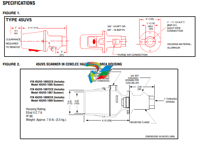
The components are contained in a cast aluminum housing sealed with an oil-resistant gasket. The
quartz lens is a planoconvex design, resulting in increased sensitivity. Also included in the scanner is
an electromagnetic shutter that permits a self-checking circuit to verify that the scanner and signal
circuits are producing valid flame presence or absence information. During the shutter closed period,
the detector’s optical path is blocked from flame radiation, allowing the amplifier control to verify
the proper operation of the ultraviolet tube. While the shutter is open, flame presence or absence is
detected. The resultant scanner output (while flame is detected) is a continuous, periodically interrupted, pulsed flame signal which is a prerequisite for energizing the associated Fireye control’s
Flame Relay.
1. AN ACCEPTABLE SCANNER LOCATION MUST ENSURE THE FOLLOWING:
— Reliable pilot flame detection.
— Reliable main flame detection.
— Rejection of pilot flame too short or in the wrong position to ignite the main flame reliably,
thus prohibiting main fuel admission.
NOTE: Reliable signals must be obtained at all air flows and furnace loads (ranges of fuel firing).

2. If combustion air enters the furnace with a rotational movement of sufficient velocity to deflect
pilot flame in direction of rotation, position the scanner 0 to 30 degrees downstream of the pilot
burner and close to the periphery of the throat where the ultraviolet radiation is at a maximum.
(See Figure 4).
3. Having determined an appropriate location for the sight tube, cut a clearance hole for a 2 inch
pipe through the burner plate. If register vanes interfere with the desired line of sight, the interfering vane(s) should be trimmed to assure an unobstructed viewing path at all firing levels, see
Figure 3.
4. Mount scanner sight pipe by either:
— Centering a Fireye No. 60-1664-3 (NPT) or 60-1664-4 (BSP) swivel mount over the hole
and installing the sight pipe on the swivel mount,
or
— Inserting the end of the sight pipe into the hole, aligning the pipe to the desired viewing
angle and tack welding. (Welding must be adequate to temporarily support the weight of the
installed scanner). The sight pipe should be arranged to slant downward so that the dirt and
dust will not collect in it.

When a satisfactory sighting position has been confirmed by operational test, (see section on
alignment), the sight pipe should either be firmly welded in place or, if the swivel mount is used,
the base position should be secured by tightening the three hex head cap screw located on the
swivel mount ring. In certain older style swivel mounts, tack welding may be required.
6. Excessive flame signal can affect flame discrimination and prevent the control connected to the
scanner from performing properly. To reduce the signal level of the tube, or improve flame discrimination, orifices may be installed to decrease the scanner’s field of view and reduce its sensitivity. Installation of the orifice disk is shown in Figure 6.
7. The scanner viewing window must be kept free of contaminants (oil, smoke, soot, dirt) and the
scanner temperature must not exceed its maximum rating. Both requirements will be satisfied by
continuous injection of purge air.
The scanner mounting may be made with provision for purge air through the 3/8” opening as shown
in Figure 6, Item A or C, or through a 1" tee/wye connection as shown in Figure 6, Item B. Normally
only one of the two connections is provided with purge air and the other is plugged. When a Fireye
coupling is used as shown in Figure 6, the 1" tee/wye connection is used for the purge air (plug 3/8”
opening).
Under normal temperature conditions, with clean burning fuels and moderate ambient temperature
conditions, purge air flow of approximately 4 SCFM (113 L/min) is generally adequate. A 0.1 psig
positive pressure difference between the atmosphere and boiler pressure measured at right angle to the
purge air flow, should result in a purge air flow of 4 SCFM. Up to 15 SCFM (425 L/min) may be
required for fuels that may produce high levels of smoke of soot or for hot environments to maintain
scanner internal temperature within specifications.
NOTE: The maximum viewing field of the lens is one inch per foot. Do not use more than one foot of
one inch sight pipe. Increase sight pipe diameter one inch for every additional foot of sight pipe
length used, to avoid restricting the scanner’s field of view. Temperature in the scanner housing
should not exceed those temperature limits listed in the specifications. Excessive temperatures will
shorten scanner life.

CAUTION: Ultra-violet tubes can simulate flame when exposed to high levels of “X” and GAMMA
radiation. The table below indicates the maximum dose of radiation that a UV tube can be exposed to
safely.

SCANNER WIRING
All FIREYE controls are protected against short-circuited scanner input terminals. The following
recommendations apply for scanner control wiring:
• Keep scanner wiring as short as possible.
• Use wires rated for scanner voltage and its ambient conditions (temperature, humidity, oil resistant, flame retardant, etc.)
• Do not run scanner wires in the same conduit as other electrical wires.
• Avoid wire loops and poor groundings.
• Keep high voltage ignition wires well away from scanner wires.
The 45UV5 self-check scanner has four 6 foot (1800mm) leads:
45UV5-1005 & 1105:
Two black leads which power the shutter from the associated control and two red leads which drive
the UV tube and carry the flame signal to the control amplifier.

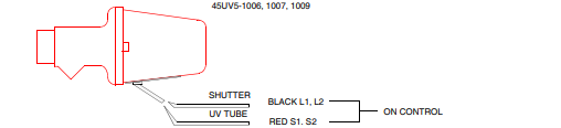
45UV5-1006, 1007 & 1009:
Two black leads which power the shutter via L1 & L2 and two red leads which drive the UV tube
and carry the flame signal to S1 & S2 on the control.
If it is necessary to extend the scanner wiring, the following instructions apply:
Scanner wires should be installed.in a separate conduit. The wires from several scanners may be
installed in a common conduit.
45UV5-1006, 1007, 1009.
1. Selection of wire
— Use #14, 16, or 18 wire with 75 C, 600 volt insulation for up to 100 foot distances (signal
loss approximately 20% at 100 feet).
— Asbestos insulated wire should be avoided.
— Multiconductor cable is not recommended without prior factory approval.
— Extended Scanner Wiring. For extended scanner wiring up to 1500 feet, and for shorter
lengths to reduce signal loss, use a shielded wire (Belden 8254-RG62U) coaxial cable, or
equal for each red wire of the 45UV5. The ends of the shielding must be taped individually
on both ends and not grounded.
For multiple burner installations:
2. Distances are decreased when more than one set of scanner leads are installed in a common conduit. For example, the maximum distance for 2 scanners is 750 feet and for 3 or more scanners
the distance decreases to 500 feet.
3. High voltage ignition wiring should not be installed in the same conduit with flame detector
wires.
WARNING: DO NOT CONNECT 45UV5 SCANNERS IN PARALLEL
45UV5-1005, 1105
1. Up to 25 foot conduit run.
— Use #18 AWG or heavier, 600V 90C minimum rated wire, installed in conduit.
2. Over 25 to 300 feet maximum:
— Use #18 AWG or heavier, 600V, 75C rated wire for the two black leads (shutter).
— Extended Scanner Wiring. For extended scanner wiring up to 1500 feet, and for shorter
lengths to reduce signal loss, use a shielded wire (Belden 8254-RG62U) coaxial cable, or equal
for each red wire of the 45UV5. The ends of the shielding must be taped individually on both
ends and not grounded.
For multiple burner installations:
3. Distances are decreased when more than one set of scanner leads are installed in a common conduit. For example, the maximum distance for 2 scanners is 750 feet and for 3 or more scanners the
distance decreases to 500 feet.
4. High voltage ignition wiring should not be installed in the same conduit with flame detector wires.
ALIGNMENT AND ADJUSTMENTS
The following procedures are recommended to ensure optimum flame detection and discrimination.
Flame discrimination is the ability to see only one burner or one pilot with other burners or pilots operating nearby. These procedures should be used whenever parts are replaced, when the scanner has been
moved, when the flame shape is altered (additional fuels, new burners, burner/register modifications)
as well as on all new installations.
Pilot Flame Scanner
1. Apply power to scanner and associated control.
2. Start pilot.
3. Adjust scanner sighting to detect pilot flame in the manner shown in Figure 4.
4. When flame is properly sighted, the flame signal should correspond to the acceptable ranges indicated in the appropriate bulletin for each compatible FIREYE control. If readings fluctuate widely,
readjust scanner sighting until highest, steadiest reading is obtained.
5. Spark Rejection Test: When the proper signal reading has been obtained, make sure that the scanner and the associated control do not respond to the ignition spark. This is accomplished by cutting
off the fuel to the pilot and attempting to start the pilot using the spark igniter. If the system
responds to the spark, the sighting should be realigned.
Minimum Pilot Test
This test assures that the flame detector will not detect a pilot flame too small to reliably light off the
main flame. The test should be made on every new installation, scanner replacement, and following
any repositioning of the flame detector. THE MINIMUM PILOT TESTS MUST BE ACCOMPLISHED BY A TRAINED AND QUALIFIED BURNER TECHNICIAN.

-
 Hirschmann RS20-1600M2T1SDAEHH03.1.02 Rail Switch
 -
 Hirschmann BRS30-24TX Industrial Rail Switch
 -
 Hirschmann RSPM20-4T14T1EV9HHS999.9.99 Managed Ethernet Switch
 -
 Hirschmann BELDEN RS40-0009CCCCSDAPHH09.0.14 / RS400009CCCCSDAPHH09014
 -
Hirschmann RS40 Rail Switch RS40-0009CCCCSDAE
-
 Hirschmann BELDEN RS30-0802T1T1SDAP / RS300802T1T1SDAP Fully Managed Layer 2 Compact Rail Switch
 -
 Hirschmann BELDEN RS20-0800M2M2SDAUHH / RS200800M2M2SDAUHH
 -
 Hirschmann EAGLE30-04022O6TT999SCCY9HSE3F Industrial Firewall Router Switch
 -
 Hirschmann RS20-1600T1T1SDAEHH09.0.14 RS20 Rail Mount Ethernet Switch
 -
 Hirschmann EAGLE0200T1T1TDDY90000HHE05.3.03 Industrial Security Router
 -
Hirschmann - BELDEN MIPP-AD-1L9P
-
 HIRSCHMANN RSPM20-4Z64Z6TV9HHS9 942 106-999 RAIL SAFETY SWITCH
 -
 HIRSCHMANN FIBEROPTIC MODULE FIP P/N: OZDFIPG3T
 -
 HIRSCHMANN RS20-1600M2M2SDAUHH Ethernet rack-mounted switch
 -
 HIRSCHMANN BELDEN RS20-0400T1T1SDAEHH04.0.01 / RS200400T1T1SDAEHH04001
 -
HIRSCHMANN MM2-4FXM3 MICE Media Module
-
HIRSCHMANN RS20-0800M2M2SDAE Industrial Ethernet Rail Switch
-
 Hirschmann RS20-2400T1T1SDAP / RS20-2400T1T1SDAPHH05.0.02
 -
 GE MLJ1005B010H00C MLJ Digital Synchromism Check
 -
 ALSTOM MICROTECH DX21-M2 Digital Excitation Controller
 -
HIRSCHMANN BRS20-1200ZZZZ-STCY99HHSES
-
 HIRSCHMANN MM3-4FXM2 MICE Media Module
 -
Hirschmann RSB20-0800T1T1SAABHH 8Port ENet Rail Switch RSB20
-
 Hirschmann MACH102-8TP Ethernet Switch
 -
 SAACKE DDZ-M marine steam pressure atomizer
 -
 SAACKE SKV-A marine rotary cup atomizer
 -
 SAACKE Seavis HMI05e
 -
 Kollmorgen MMC-SD-2.0-230 Servo Drive 100-240VAC 2KW 10A Output 3PH 100-240VAC
 -
 Kollmorgen Servo drive CR10550
 -
 Kollmorgen AKD-P01207-NACN-0054 Servo Driver
 -
 Kollmorgen S406M-CA-036 Servostar
 -
.png) Kollmorgen AKD-B02407-NAAN-0000 Digital Servo Drive
Kollmorgen AKD-B02407-NAAN-0000 Digital Servo Drive -
 Kollmorgen SERVOSTAR S406AM-CA Digital Servo Drive
 -
 KOLLMORGEN SERVOSTAR 603-AS SERVO AMPLIFIER_SERVOSTAR603AS_S60301
 -
Kollmorgen S700 Servo Controller (S70602-NANANA-NA)
-
 Kollmorgen MPK411 controller
 -
 KOLLMORGEN MMC-SD-1.3-460-D Smart Drive
 -
 KOLLMORGEN AKM21C-CKB2AA-00 / AKM21CCKB2AA00 Servomotor
 -
 BECKHOFF AX5106-0000-0200 | Digital Compact Servo Drives 1-channel
 -
 BECKHOFF C3620-0000 INDUSTRIAL COMPUTER (MOTORSHELVES)
 -
 Beckhoff EK1960-0000 TwinSAFE Compact Controller
 -
 Beckhoff C6930-0050 Control Cabinet Industrial PC
 -
 Beckhoff CP7711-0001-0030 Industrial Computer Detection
 -
 Beckhoff CX1001-0111 Embedded PC CPU Module
 -
 Beckhoff C6017-0020 | Ultra-compact Industrial PC
 -
 Beckhoff EK1322 | 2-port EtherCAT P junction with feed-in
 -
 Beckhoff CP2219-0010 Panel
 -
 BECKHOFF C6015-0020 ULTRA COMPACT INDUSTRIAL PC
 -
 BECKHOFF CX2030-0120/Standard CPU Module Embedded PC Windows PLC controller
 -
 Beckhoff CP7721-1090-0020 Panel PC
 -
 Beckhoff PC CPU Module CX5130-0175
 -
 Beckhoff C6920-0050 Control Cabinet
 -
 Beckhoff EL6631 EtherCAT 2-Port Communication Interface, Profinet RT Controller
 -
 Beckhoff CP6202-0001-0060 touch screen panel PC
 -
 Beckhoff CP3916-1002-0000 Multi-Touch Control Panel
 -
 Beckhoff EP1809-0021 | EtherCAT Box, 16-channel digital input, 24 V DC, 3 ms, M8Preferred type
 -
 Beckhoff CX8190 PLC Embedded Industrial PC Ethernet Controller
 -
 Beckhoff CX2100-0914 Power Supply for External
 -
 Beckhoff Automation CP6906-0001-0000 HMI
 -
 Beckhoff EP7342-0002 Module
 -
 Beckhoff CX1020-0112 / CX1100-0910 / CX1020-N010 / CX1100-0003 Windows CPU
 -
 Beckhoff EP7211-0034 EtherCAT Box 1 Channel Motion Interface
 -
 Beckhoff C6240-0030 Control cabinet Industrial PC
 -
 beckhoff motherboard CB1052-0004 CB1052-0004
 -
 Beckhoff AX2006-AS Servo Drive / Variable Frequency Drive
 -
BECKHOFF CP6207-0001-0020 NSMP
-
 Beckhoff C6930-1142-0060 Industrial Computer
 -
 Beckhoff FC7501-0000 interface card
 -
 Beckhoff CX5140-0175 Embedded PC PLC CPU CX5140 Industrial Controller
 -
 Beckhoff CP7802-1100-0010: High-End IP65 Control Panel with DVI/USB Extended Interface
 -
BECKHOFF CP3716-1058-0010 CONTROL PANEL
-
 Beckhoff AX8108-0000 Single-Axis Module
 -
 Beckhoff CU8851-0000 | USB extension, USB Extended 2.0 receiver box
 -
Beckhoff C6017-0030 | Ultra-compact Industrial PC
-
 Beckhoff CX1001-0120/CX10010120.cx1000-n001.cx1000-n000 System Overview
 -
 Beckhoff CPU Module CX5140-0155/4GB CPU Module
 -
 Beckhoff CP6533-0001-005: Built-in Panel PC with High-Definition Multi-Touch Control
 -
 Beckhoff EL5042 | EtherCAT Terminal, 2-channel encoder interface, BiSS® C
 -
 Beckhoff C6920-1080-0040: Premium Control Cabinet Industrial PC
 -
 Beckhoff C6920-0060 | Control cabinet Industrial PC
 -
 Beckhoff Embedded-PC CX5010-1121
 -
 Beckhoff CB3050-0010 Mainboard Motherboard
 -
 Beckhoff PLC module CX1020-0000 Basic CPU module (service phase)
 -
 Beckhoff CP7812-1056-0010 15" Multitouch Display Control Panel
 -
 Beckhoff CX5120-0115 /2GB Controller Module
 -
 Beckhoff CP7201-1000-0000 Industrial Panel PC
 -
 Beckhoff Servo Motor AM8061-0JH1-0000
 -
 BECKHOFF CP6503-0001-0050 Built-in Panel PC
 -
Beckhoff CP3919-0010 Display G190ETN01.2 19" PCT V04. Multi-touch Control Panel
-
 Beckhoff CX5110-0112-9020/000368201 Embedded PC Intel Atom Processor
 -
 Beckhoff AX8206-0000 Dual-Axis Module
 -
Beckhoff Nail Operating Terminal CP7032-1031-0010
-
Beckhoff AM8042-0EH1-0000 Servomotor 4.10 Nm (M0), F4 (87 mm)
-
 Beckhoff EK9300 Beckhoff CPU Module
 -
Beckhoff CP3224-0020 Multitouch-Panel-PC
-
 Beckhoff CP2712-0000 12.1" 24VDC Touch Screen WMD0
 -
 BECKHOFF CX5240-0195 / 0000289234 Embedded PC 40 GB CFast Card
 -
 Beckhoff CP6932-1000-0000 Control Panel
 -
 BECKHOFF CX5120-0121 PLC Module
 -
 Beckhoff EL3218 | EtherCAT Terminal, 8-channel analog input
 -
Beckhoff C6640-0050 | Control cabinet Industrial PC
-
 Beckhoff Cx5130-0120/4GB Embedded-PC
 -
 BECKHOFF CX2030-0122 PLC PROCESSOR
 -
 BECKHOFF CX5020-0122 Controller Module
 -
 Beckhoff CP3915-0000 Multitouch Panel
 -
 BECKHOFF EL3014 | EtherCAT Terminal
 -
 BECKHOFF Industrial Computer c6920-1057-0030
 -
 Beckhoff CX5130-0141/4GB CX5130-0141 Embedded PC
 -
 Beckhoff C6240-1052-0040 4-086-06-3073 Industrial Computer
 -
 Beckhoff CX5140-0135 /4GB High-Performance Embedded Industrial PC
 -
 Beckhoff C6515-1001-0000 Industrial PC
 -
 Beckhoff AX5103-0000-0200 - Digital Compact Servo Drives
 -
 Beckhoff CX2030-0130-1003/4GB Basic CPU module
 -
 Beckhoff AX8620-0000 Power Supply Module
 -
 Beckhoff CX9020-0111 module with
 -
 Beckhoff EL7332 PLC Module
 -
 BECKHOFF CP7709-0001-0020 HMI
 -
 Beckhoff CX5120-0155/2GB Embedded PC
 -
 BECKHOFF CP7037-1037-0010 OPERATOR INTERFACE TOUCHSCREEN
 -
 Beckhoff EK9000 | ModbusTCP/UDP Bus Coupler
 -
 Beckhoff Touch Panel Screen CP6020 -0000-0000
 -
 Beckhoff CX2020-0121 Module FAST Shipping
 -
 Beckhoff CX2030-0125 Basic CPU Module
 -
 Beckhoff CP3918-0000 Multi-Touch 18.5" Control Panel
 -
 Automotion LC4A00010 DC BL Motor Control, ATS, Sub Assy, SCP, 115VAC,
 -
 500T-115VAC - VAS ENGINEERING - DORIC 500 SERIES DIGITAL TEMP INDICATOR
 -
 Honeywell X-DCS2000/EN Digital Integrated System Manager 50/60Hz 100-240V #4
 -
 Kollmorgen S60600 Servostar600 606-Fan 4 kVA, 6 A, 3 X 230 - 480 V


