MotorolaMVME187 RISC Single Board Computer Installation Guide MVME187IG/D4
A functional description of the Parallel Port Interface starts on page
2-20.
Ethernet Transceiver Interface
The Ethernet transceiver interface is located on the MVME187, and
the industry standard connector is located on the MVME712X
transition module.
A functional description of the Ethernet Interface starts on page
2-21.
Serial
Port Function Synchronous/
Asynchronous Signals Bit Rates
1 Minimum Asynchronous RXD, CTS, TXD, and RTS
2
and
3
Full Asynchronous RXD, CTS, DCD, TXD, RTS,
and DTR
4 Full Both RXD, CTS, DCD, TXD, RTS,
and DTR
Synchronous up
to 64 k bits per
second
187Bug Firmware
The MVME187Bug debug monitor firmware (187Bug) is provided
in two of the four EPROM sockets on the MVME187.
It provides:
❏ Over 50 debug commands
❏ Up/down load commands
❏ Disk bootstrap load commands
❏ A full set of onboard diagnostics
❏ A one-line assembler/disassembler
The 187Bug user interface accepts commands from the system
console terminal.
187Bug can also operate in a System Mode, which includes choices
from a service menu.
Features
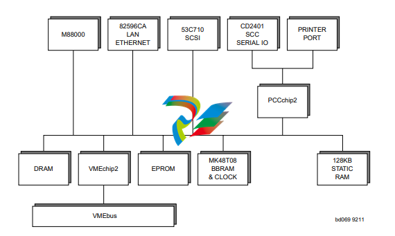
❏ M88000 Microprocessor (one MC88100 MPU and two
MC88200 or MC88204 CMMUs)
❏ 4/8/16/32/64MB of 32-bit DRAM with parity or
4/8/16/32/64/128/256MB of 32-bit DRAM with ECC
protection
❏ Four 44-pin PLCC ROM sockets (organized as two banks of
32 bits)
❏ 128KB Static RAM (with optional battery backup as a factory
build special request)
❏ Status LEDs for FAIL, STAT, RUN, SCON, LAN, +12V (LAN
power), SCSI, and VME.
❏ 8K by 8 static RAM and time of day clock with battery backup
❏ RESET and ABORT switches
❏ Four 32-bit tick timers for periodic interrupts
❏ Watchdog timer
❏ Eight software interrupts
❏ I/O
– SCSI Bus interface with DMA
– Four serial ports with EIA-232-D buffers with DMA
– Centronics printer port
– Ethernet transceiver interface with DMA
❏ VMEbus interface
– VMEbus system controller functions
– VMEbus interface to local bus (A24/A32, D8/D16/D32
and D8/D16/D32/D64BLT) (BLT = Block Transfer)
– Local bus to VMEbus interface (A16/A24/A32,
D8/D16/D32)
– VMEbus interrupter
– VMEbus interrupt handler
– Global CSR for interprocessor communications
– DMA for fast local memory - VMEbus transfers
(A16/A24/A32, D16/D32 and D16/D32/D64BLT)
Specifications
Conformance to Requirements
These boards are designed to conform to the requirements of the
following specifications:
❏ VMEbus Specification (IEEE 1014-87)
❏ EIA-232-D Serial Interface Specification, EIA
❏ SCSI Specification
Table 2-1. MVME187 General Specifications
Characteristics Specifications
Power requirements
(with all four EPROM sockets
populated and excluding
external LAN transceiver)
+5 Vdc (+/-5%) 3.5 A (typical), 4.5 A (maximum)
(at 25 MHz, with 32MB parity DRAM)
5.0 A (typical), 6.5 A (maximum)
(at 33 MHz, with 128MB ECC DRAM)
+12 Vdc (+/-5%) 100 mA (maximum)
(1.0 A (maximum) with offboard LAN
transceiver)
-12 Vdc (+/- 5%) 100 mA (maximum)
Operating temperature 0˚ to 55˚ C at point of entry of forced air
(approximately 490 LFM)
Storage temperature -40˚ to +85˚ C
Relative humidity 5% to 90% (non-condensing)
Physical
dimensions
Double-high
VMEboard
PC board with
mezzanine
module only
Height 9.187 inches (233.35 mm)
Depth 6.299 inches (160.00 mm)
Thickness 0.662 inches (16.77 mm)
PC board with
connectors and
front panel
Height 10.309 inches (261.85 mm)
Depth 7.4 inches (188 mm)
Thickness 0.80 inches (20.32 mm)
Board Level Overview

Connectors
The MVME187 has two 96-position DIN connectors: P1 and P2.
❏ P1 rows A, B, C, and P2 row B provide the VMEbus
interconnection.
❏ P2 rows A and C provide the connection to the SCSI bus,
serial ports, Ethernet, and printer.
Adapters
I/O on the MVME187 is connected to the VMEbus P2 connector.
The main board is connected to the transition modules through a P2
adapter board and cables.
Transition Modules
MVME712X transition modules provide configuration headers and
provide industry standard connectors for the I/O devices. Refer to
Figure 3-3 on page 3-22.
❏ The MVME187 supports the transition modules MVME712-
12, MVME712-13, MVME712M, MVME712A, MVME712AM,
and MVME712B (referred to in this manual as MVME712X,
unless separately specified).
Transition modules and adapter boards are covered in
MVME712M, Transition Module and P2 Adapter Board User's Manual,
and MVME712A, MVME712-12, MVME712-13, MVME712A,
MVME712AM, and MVME712B Transition Modules and LCP2
Adapter Board User's Manual.
ASICs
The MVME187 board features several Application Specific
Integrated Circuits (ASICs) including:
❏ VMEchip2
❏ PCCchip2
❏ MEMC040
❏ MCECC
All programmable registers in the MVME187 that reside in ASICs
are covered in the Single Board Computers Programmer's Reference
Guide.
VMEchip2 ASIC
Provides the VMEbus interface. The VMEchip2 includes:
❏ Two tick timers
❏ Watchdog timer


.png)


.png)


.png)


