
EMERSONUSER’S MANUAL MANUEL DE L’UTILISATEUR MANUAL DEL USUARIO UW40T SERIES
DIGITAL TELEVISION TRANSITION NOTICE
This device contains a digital television tuner, so it should receive digital over the air
TV programming, with a suitable antenna, after the end of full-power analog TV
broadcasting in the United States on June 12, 2009. The nationwide switch to digital
television broadcasting will be complete on June 12, 2009, but your local television
stations may switch sooner. After the switch, analog-only television sets that receive
TV programming through an antenna will need a converter box to continue to receive
over-the-air TV. Watch your local stations to find out when they will turn off their
analog signal and switch to digital-only broadcasting.
For more information, call the FCC at 1-888-CALL-FCC (1-888-225-5322) or see
www.DTV.gov. For information on the TV Converter program, and on government
coupons that may be used toward the purchase of one, see www.dtv2009.gov, or call
the NTIA at 1-888-DTV-2009.
ENERGY STAR DISCLAIMER
This Westinghouse product has earned the ENERGY STAR® for meeting U.S.
Federal energy efficiency guidelines as set by the Department of Energy and
Environmental Protection agency. The ENERGY STAR® program exists to provide
energy saving guidelines and help promote energy efficient products and practices.
Changes to certain features, settings and functions of this TV can change and/or
increase its power consumption. Depending on how settings are changed, power
consumption may exceed the limits required for ENERGY STAR® qualification. This
Westinghouse TV will operate at optimal energy efficiency in “Home” mode.
IMPORTANT INFORMATION
Warnings
To reduce the risk of fire or electric shock:
• Do not expose this product to rain or moisture.
• Do not remove the rear cover. There are no user-serviceable parts inside.
Refer all servicing requirements to qualified service personnel.
• The plug should be connected to a mains socket outlet with a protective
earthing connection.
The lightning flash with arrowhead inside an equilateral
triangle symbol is intended to alert the user to the presence
of uninsulated dangerous voltage within the product's
enclosure that may be of sufficient magnitude to constitute a
risk of electric shock.
The exclamation inside an equilateral triangle symbol is intended to
alert the user to related operating and maintenance instructions in
the user documentation accompanying the product.
WARNING!
This device must be operated with the original power supply.
WARNING!
To prevent injury, this apparatus must be securely attached to the floor/wall in
accordance with the installation instructions.
CAUTION:
The power supply outlet should be located near the LED TV and should be easily
accessible.
Always use the appropriate AC cord that is certified for your specific country.
Some examples are listed below:
• USA – UL
• Canada – CSA
• Japan – Electric Appliance Control ActIMPORTANT INFORMATION
Warnings
To reduce the risk of fire or electric shock:
• Do not expose this product to rain or moisture.
• Do not remove the rear cover. There are no user-serviceable parts inside.
Refer all servicing requirements to qualified service personnel.
• The plug should be connected to a mains socket outlet with a protective
earthing connection.
The lightning flash with arrowhead inside an equilateral
triangle symbol is intended to alert the user to the presence
of uninsulated dangerous voltage within the product's
enclosure that may be of sufficient magnitude to constitute a
risk of electric shock.
The exclamation inside an equilateral triangle symbol is intended to
alert the user to related operating and maintenance instructions in
the user documentation accompanying the product.
WARNING!
This device must be operated with the original power supply.
WARNING!
To prevent injury, this apparatus must be securely attached to the floor/wall in
accordance with the installation instructions.
CAUTION:
The power supply outlet should be located near the LED TV and should be easily
accessible.
Always use the appropriate AC cord that is certified for your specific country.
Some examples are listed below:
• USA – UL
• Canada – CSA
• Japan – Electric Appliance Control Act
NOTICES
Important Notices Concerning Power Cord Selection
The specific power cord for this LED TV is enclosed and has been selected
according to the country of destination. Use the enclosed power cord to prevent
electric shock. Observe the following guidelines if it is necessary to replace the
original cord set, or if there is no cord set enclosed. The female receptacle of the
cord set must meet IEC-60320 requirements and should look like Figure A1 below:

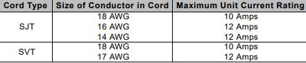
For the United States and Canada
In the United States and Canada the male plug is a NEMA5-15 style (Figure A2),
UL-listed, and CSA-labeled. For LED TVs that are to be placed on a desk or table,
type SVT or SJT cord sets may be used. For LED TVs that are to be placed directly
on the floor, only SJT type cord sets may be used. The cord set must be selected
according to the current rating for the LED TV. Consult the table below for the
selection criteria of power cords used in the United States and Canada
FCC COMPLIANCE STATEMENT
This equipment has been tested and complies with the limits for a Class B digital
device, pursuant to part 15 of the FCC Rules. These limits are designed to provide
reasonable protection against harmful interference in a residential installation. This
equipment generates, uses, and can radiate radio frequency energy, and may cause
harmful interference to radio communications if not installed and used in accordance
with the instructions. However, there is no guarantee that interference will not occur
in a particular installation. If this equipment does cause harmful interference to radio
or television reception, which can be determined by turning the equipment off and
on, the user is encouraged to try to correct the interference by one or more of the
following measures:
• Reorient or relocate the receiving antenna.
• Increase the distance between the LED TV and the receiver.
• Connect the LED TV to an outlet on a circuit separate from to which the
receiver is connected.
• If the interference persists even after performing the above measures,
consult the Westinghouse Service Center or an experienced radio/TV
technician for assistance.
FCC Warning
To assure continued FCC compliance, use a grounded power supply cord and the
provided shielded video interface cable with bonded ferrite cores. If a BNC cable is
used, use only a shielded BNC (5) cable. Also, any unauthorized changes or
modifications not expressly approved by the manufacturer will void the user's
authority to operate this device.
IMPORTANT SAFETY INSTRUCTIONS
Make sure to note and follow all warnings and instructions marked on the LED TV.
Observe the following safety instructions.
• Read these instructions.
• Keep these instructions.
• Heed all warnings.
• Follow all instructions.
• Do not use this apparatus near water.
• Clean only with dry cloth.
• Do not block any ventilation openings. Install in accordance with the
manufacturer’s instructions.
• Do not install near any heat sources such as radiators, heat registers,
stoves, or other apparatus (including amplifiers) that produce heat.
• Do not defeat the safety purpose of the polarized or grounding-type plug. A
polarized plug has two blades with one wider than the other. A grounding
type plug has two blades and a third grounding prong. The wide blade or the
third prong are provided for your safety. If the provided plug does not fit into
your outlet, consult an electrician for replacement of the obsolete outlet.
• Protect the power cord from being walked on or pinched particularly at plugs,
convenience receptacles, and the point where they exit from the apparatus.
• Only use attachments/accessories specified by the manufacturer.
• Use only with the cart, stand, tripod, bracket, or table specified by the
manufacturer, or sold with the apparatus. When a cart is used, use caution
when moving the cart/apparatus combination to avoid injury from tip-over.
• Unplug this apparatus during lightning storms or when unused for long
periods of time.
• Refer all servicing to qualified service personnel. Servicing is required when
the apparatus has been damaged in any way, such as power-supply cord or
plug is damaged, liquid has been spilled or objects have fallen into the
apparatus, the apparatus has been exposed to rain or moisture, does not
operate normally, or has been dropped.
Circuit Overload
Do not overload wall outlets, extension cords, or power strips. This can result in a fire
or electronic shock.
Power Cord Protection
Power supply cords should be routed so that they are not likely to be walked on or
pinched by items placed upon or against them. Periodically inspect the cords for
damage. Install the LED TV near a wall socket outlet where the power cord can be
readily accessed.
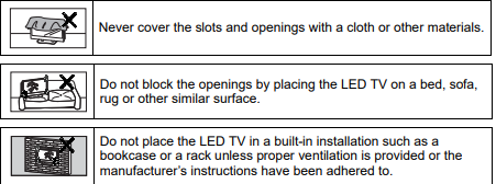
Ventilation
The slots and openings on the cabinet are provided for necessary ventilation. To
ensure reliable operation of the LED TV and to protect it from overheating, these
slots and openings must never be blocked or covered
WARNINGS AND PRECAUTIONS
• Do not orient the LED TV towards direct sunlight to reduce glare.
• If the LED TV will not be used for a long period of time, unplug the unit and
remove the batteries from the remote control.
• Avoid touching the display screen by hand or any object.
• Never remove the rear cover. The LED TV interior contains high-voltage
parts. You may be seriously injured if you touch them.
• Always handle the LED TV with caution when moving it.
• Do not install the LED TV in airtight compartments, or in areas where it can
be exposed to water or high temperature.
• Ensure that the area around the LED TV is clean and free of moisture.
• Do not place anything on the LED TV that can hinder heat dissipation.
• Do not place naked flame sources, such as lighted candles, on or near the
LED TV.
• Do not place anything on the LED TV that can cause liquid to splash on it
(e.g. flower vase).
• Do not place heavy objects on the LED TV, audio/video cables, or power
cord.
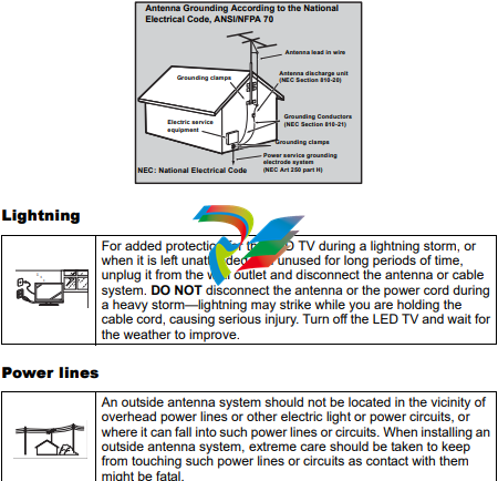
ANTENNA INSTALLATION SAFETY
Outdoor Antenna Grounding
If an outside antenna or cable system is connected to the LED TV, be sure the
antenna or cable system is grounded to prevent voltage surges and built-up static
charges. Article 810 of the National Electrical Code, ANS/NFPA 70, provides
information on proper grounding of the mast and supporting structure, grounding of
the lead-in wire to an antenna discharge unit, connection to grounding electrodes,
and requirements for the grounding electrode.
CLEANING THE LED TV
To clean the screen:
1 Wipe the screen with a clean, soft, lint-free cloth. This removes dust and other
particles.
2 If it is still not clean, apply a small amount of non-ammonia, non-alcohol
based glass cleaner onto a clean, soft, lint-free cloth, and wipe the screen.
To clean the case:
1 Wipe the case with a soft, dry cloth.
2 If it is still not clean, apply a small amount of non-ammonia, non-alcohol
based, mild non-abrasive detergent onto a clean, soft, lint-free cloth, then
wipe the surface.
Dolby-Digital Notice
Manufactured under license from Dolby Laboratories. Dolby and the double-D
symbol are registered trademarks of Dolby Laboratories.
• Make sure the LED TV is turned off and the power cord is
disconnected from the power outlet.
• Never spray or pour any liquid directly onto the screen or the
case.
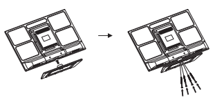
LED TV BASE
INSTALLING THE LED TV BASE
1 Open the LED TV carton box.
2 Remove the LED TV base.
3 Remove the plastic bag.
4 Remove the two top carton stabilizers from the LED TV.
5 Remove the protective plastic covering the LED TV.
6 Grasp the two sides of the LED TV and then pull it out of the carton box.
7 Remove the two bottom carton stabilizers from the LED TV.
8 Lay the LED TV on a clear, flat, and stable surface.
9 Align the base to the bottom side of LED TV and use four M6 x 10 screws to
secure it.
10 Carefully orient the LED TV in an upright position.
CAUTION:
The LED TV unit may be too heavy for one person to lift. If this is the case,
make sure to ask for assistance in handling the LED TV to prevent
physical injury and/or damage to the unit.
TV PROGRAM
Use the TV Program sub-menus to manage the channel list, language sound, and to
scan for available TV channels in your area.
Press on the remote control or MENU on the control panel to display the setup
menu screen then select TV Program to display the TV Program sub-menu. The
following options are available: Skip List, Channel Edit, MTS, Auto Search, and
Manual Add.
Skip List
Use Skip List to select the channels you want to skip.
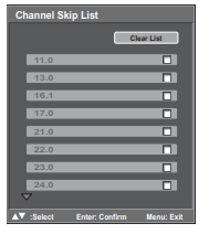
Adding Channels to Skip List
1 Use the / keys to select Skip List and press . The Channel Skip
List screen appears.
2 Use the / keys to select the desired channel.
3 Press repeatedly to check (add to the Skip list) or uncheck (clear to
the Skip list) the channels.
4 Repeat steps 2 and 3 to add more channels.
5 Press to save and exit the screen.
-
 Hirschmann RS20-1600M2T1SDAEHH03.1.02 Rail Switch
 -
 Hirschmann BRS30-24TX Industrial Rail Switch
 -
 Hirschmann RSPM20-4T14T1EV9HHS999.9.99 Managed Ethernet Switch
 -
 Hirschmann BELDEN RS40-0009CCCCSDAPHH09.0.14 / RS400009CCCCSDAPHH09014
 -
Hirschmann RS40 Rail Switch RS40-0009CCCCSDAE
-
 Hirschmann BELDEN RS30-0802T1T1SDAP / RS300802T1T1SDAP Fully Managed Layer 2 Compact Rail Switch
 -
 Hirschmann BELDEN RS20-0800M2M2SDAUHH / RS200800M2M2SDAUHH
 -
 Hirschmann EAGLE30-04022O6TT999SCCY9HSE3F Industrial Firewall Router Switch
 -
 Hirschmann RS20-1600T1T1SDAEHH09.0.14 RS20 Rail Mount Ethernet Switch
 -
 Hirschmann EAGLE0200T1T1TDDY90000HHE05.3.03 Industrial Security Router
 -
Hirschmann - BELDEN MIPP-AD-1L9P
-
 HIRSCHMANN RSPM20-4Z64Z6TV9HHS9 942 106-999 RAIL SAFETY SWITCH
 -
 HIRSCHMANN FIBEROPTIC MODULE FIP P/N: OZDFIPG3T
 -
 HIRSCHMANN RS20-1600M2M2SDAUHH Ethernet rack-mounted switch
 -
 HIRSCHMANN BELDEN RS20-0400T1T1SDAEHH04.0.01 / RS200400T1T1SDAEHH04001
 -
HIRSCHMANN MM2-4FXM3 MICE Media Module
-
HIRSCHMANN RS20-0800M2M2SDAE Industrial Ethernet Rail Switch
-
 Hirschmann RS20-2400T1T1SDAP / RS20-2400T1T1SDAPHH05.0.02
 -
 GE MLJ1005B010H00C MLJ Digital Synchromism Check
 -
 ALSTOM MICROTECH DX21-M2 Digital Excitation Controller
 -
HIRSCHMANN BRS20-1200ZZZZ-STCY99HHSES
-
 HIRSCHMANN MM3-4FXM2 MICE Media Module
 -
Hirschmann RSB20-0800T1T1SAABHH 8Port ENet Rail Switch RSB20
-
 Hirschmann MACH102-8TP Ethernet Switch
 -
 SAACKE DDZ-M marine steam pressure atomizer
 -
 SAACKE SKV-A marine rotary cup atomizer
 -
 SAACKE Seavis HMI05e
 -
 Kollmorgen MMC-SD-2.0-230 Servo Drive 100-240VAC 2KW 10A Output 3PH 100-240VAC
 -
 Kollmorgen Servo drive CR10550
 -
 Kollmorgen AKD-P01207-NACN-0054 Servo Driver
 -
 Kollmorgen S406M-CA-036 Servostar
 -
.png) Kollmorgen AKD-B02407-NAAN-0000 Digital Servo Drive
Kollmorgen AKD-B02407-NAAN-0000 Digital Servo Drive -
 Kollmorgen SERVOSTAR S406AM-CA Digital Servo Drive
 -
 KOLLMORGEN SERVOSTAR 603-AS SERVO AMPLIFIER_SERVOSTAR603AS_S60301
 -
Kollmorgen S700 Servo Controller (S70602-NANANA-NA)
-
 Kollmorgen MPK411 controller
 -
 KOLLMORGEN MMC-SD-1.3-460-D Smart Drive
 -
 KOLLMORGEN AKM21C-CKB2AA-00 / AKM21CCKB2AA00 Servomotor
 -
 BECKHOFF AX5106-0000-0200 | Digital Compact Servo Drives 1-channel
 -
 BECKHOFF C3620-0000 INDUSTRIAL COMPUTER (MOTORSHELVES)
 -
 Beckhoff EK1960-0000 TwinSAFE Compact Controller
 -
 Beckhoff C6930-0050 Control Cabinet Industrial PC
 -
 Beckhoff CP7711-0001-0030 Industrial Computer Detection
 -
 Beckhoff CX1001-0111 Embedded PC CPU Module
 -
 Beckhoff C6017-0020 | Ultra-compact Industrial PC
 -
 Beckhoff EK1322 | 2-port EtherCAT P junction with feed-in
 -
 Beckhoff CP2219-0010 Panel
 -
 BECKHOFF C6015-0020 ULTRA COMPACT INDUSTRIAL PC
 -
 BECKHOFF CX2030-0120/Standard CPU Module Embedded PC Windows PLC controller
 -
 Beckhoff CP7721-1090-0020 Panel PC
 -
 Beckhoff PC CPU Module CX5130-0175
 -
 Beckhoff C6920-0050 Control Cabinet
 -
 Beckhoff EL6631 EtherCAT 2-Port Communication Interface, Profinet RT Controller
 -
 Beckhoff CP6202-0001-0060 touch screen panel PC
 -
 Beckhoff CP3916-1002-0000 Multi-Touch Control Panel
 -
 Beckhoff EP1809-0021 | EtherCAT Box, 16-channel digital input, 24 V DC, 3 ms, M8Preferred type
 -
 Beckhoff CX8190 PLC Embedded Industrial PC Ethernet Controller
 -
 Beckhoff CX2100-0914 Power Supply for External
 -
 Beckhoff Automation CP6906-0001-0000 HMI
 -
 Beckhoff EP7342-0002 Module
 -
 Beckhoff CX1020-0112 / CX1100-0910 / CX1020-N010 / CX1100-0003 Windows CPU
 -
 Beckhoff EP7211-0034 EtherCAT Box 1 Channel Motion Interface
 -
 Beckhoff C6240-0030 Control cabinet Industrial PC
 -
 beckhoff motherboard CB1052-0004 CB1052-0004
 -
 Beckhoff AX2006-AS Servo Drive / Variable Frequency Drive
 -
BECKHOFF CP6207-0001-0020 NSMP
-
 Beckhoff C6930-1142-0060 Industrial Computer
 -
 Beckhoff FC7501-0000 interface card
 -
 Beckhoff CX5140-0175 Embedded PC PLC CPU CX5140 Industrial Controller
 -
 Beckhoff CP7802-1100-0010: High-End IP65 Control Panel with DVI/USB Extended Interface
 -
BECKHOFF CP3716-1058-0010 CONTROL PANEL
-
 Beckhoff AX8108-0000 Single-Axis Module
 -
 Beckhoff CU8851-0000 | USB extension, USB Extended 2.0 receiver box
 -
Beckhoff C6017-0030 | Ultra-compact Industrial PC
-
 Beckhoff CX1001-0120/CX10010120.cx1000-n001.cx1000-n000 System Overview
 -
 Beckhoff CPU Module CX5140-0155/4GB CPU Module
 -
 Beckhoff CP6533-0001-005: Built-in Panel PC with High-Definition Multi-Touch Control
 -
 Beckhoff EL5042 | EtherCAT Terminal, 2-channel encoder interface, BiSS® C
 -
 Beckhoff C6920-1080-0040: Premium Control Cabinet Industrial PC
 -
 Beckhoff C6920-0060 | Control cabinet Industrial PC
 -
 Beckhoff Embedded-PC CX5010-1121
 -
 Beckhoff CB3050-0010 Mainboard Motherboard
 -
 Beckhoff PLC module CX1020-0000 Basic CPU module (service phase)
 -
 Beckhoff CP7812-1056-0010 15" Multitouch Display Control Panel
 -
 Beckhoff CX5120-0115 /2GB Controller Module
 -
 Beckhoff CP7201-1000-0000 Industrial Panel PC
 -
 Beckhoff Servo Motor AM8061-0JH1-0000
 -
 BECKHOFF CP6503-0001-0050 Built-in Panel PC
 -
Beckhoff CP3919-0010 Display G190ETN01.2 19" PCT V04. Multi-touch Control Panel
-
 Beckhoff CX5110-0112-9020/000368201 Embedded PC Intel Atom Processor
 -
 Beckhoff AX8206-0000 Dual-Axis Module
 -
Beckhoff Nail Operating Terminal CP7032-1031-0010
-
Beckhoff AM8042-0EH1-0000 Servomotor 4.10 Nm (M0), F4 (87 mm)
-
 Beckhoff EK9300 Beckhoff CPU Module
 -
Beckhoff CP3224-0020 Multitouch-Panel-PC
-
 Beckhoff CP2712-0000 12.1" 24VDC Touch Screen WMD0
 -
 BECKHOFF CX5240-0195 / 0000289234 Embedded PC 40 GB CFast Card
 -
 Beckhoff CP6932-1000-0000 Control Panel
 -
 BECKHOFF CX5120-0121 PLC Module
 -
 Beckhoff EL3218 | EtherCAT Terminal, 8-channel analog input
 -
Beckhoff C6640-0050 | Control cabinet Industrial PC
-
 Beckhoff Cx5130-0120/4GB Embedded-PC
 -
 BECKHOFF CX2030-0122 PLC PROCESSOR
 -
 BECKHOFF CX5020-0122 Controller Module
 -
 Beckhoff CP3915-0000 Multitouch Panel
 -
 BECKHOFF EL3014 | EtherCAT Terminal
 -
 BECKHOFF Industrial Computer c6920-1057-0030
 -
 Beckhoff CX5130-0141/4GB CX5130-0141 Embedded PC
 -
 Beckhoff C6240-1052-0040 4-086-06-3073 Industrial Computer
 -
 Beckhoff CX5140-0135 /4GB High-Performance Embedded Industrial PC
 -
 Beckhoff C6515-1001-0000 Industrial PC
 -
 Beckhoff AX5103-0000-0200 - Digital Compact Servo Drives
 -
 Beckhoff CX2030-0130-1003/4GB Basic CPU module
 -
 Beckhoff AX8620-0000 Power Supply Module
 -
 Beckhoff CX9020-0111 module with
 -
 Beckhoff EL7332 PLC Module
 -
 BECKHOFF CP7709-0001-0020 HMI
 -
 Beckhoff CX5120-0155/2GB Embedded PC
 -
 BECKHOFF CP7037-1037-0010 OPERATOR INTERFACE TOUCHSCREEN
 -
 Beckhoff EK9000 | ModbusTCP/UDP Bus Coupler
 -
 Beckhoff Touch Panel Screen CP6020 -0000-0000
 -
 Beckhoff CX2020-0121 Module FAST Shipping
 -
 Beckhoff CX2030-0125 Basic CPU Module
 -
 Beckhoff CP3918-0000 Multi-Touch 18.5" Control Panel
 -
 Automotion LC4A00010 DC BL Motor Control, ATS, Sub Assy, SCP, 115VAC,
 -
 500T-115VAC - VAS ENGINEERING - DORIC 500 SERIES DIGITAL TEMP INDICATOR
 -
 Honeywell X-DCS2000/EN Digital Integrated System Manager 50/60Hz 100-240V #4
 -
 Kollmorgen S60600 Servostar600 606-Fan 4 kVA, 6 A, 3 X 230 - 480 V


