
VMIVME-7807 VME-7807RC* Intel® Pentium® M-Based VME SBC
Pentium® M-based, single board computers (SBCs) in a single-slot, passively cooled,
VME Eurocard form factor. These products utilize the advanced technology of Intel®’s
855GME chipset.
VMIVME-7807
VME-7807RC*
Intel® Pentium® M-Based VME SBC
GE Fanuc Embedded Systems’ VMIVME-7807/VME-7807RC are full featured
Pentium® M-based, single board computers (SBCs) in a single-slot, passively cooled,
VME Eurocard form factor. These products utilize the advanced technology of Intel®’s
855GME chipset.
The VMIVME-7807/VME-7807RC provide features typically found on desktop
systems such as:
• 1.0GB DDR SDRAM using one SODIMM and an optional 512MB of solder-in
memory for a maximum of 1.5GB
• Built-in SVGA support (front panel connection)
• Digital video controller (rear I/O) DVI-D with dual head display capabilities
• 10/100 Mbit Ethernet controller (front panel connection)
• Dual Gigabit Ethernet supporting (front panel or rear I/O)
• Optional P0 with VITA 31.1 interface
• Serial ATA (SATA) support (rear I/O)
• Serial port COM1 (front panel connection)
• Ultra IDE drive support (rear I/O)
• Real-Time clock/calendar
• Front panel reset switch
• Miniature speaker
• Keyboard/Mouse port (front panel connection)

The 855GME chipset allows the VMIVME-7807/VME-7807RC to provide enhanced
features such as integrated video and Ultra ATA/100 IDE support. The
VMIVME-7807/VME-7807RC are capable of executing many of today’s desktop
operating systems such as Microsoft®’s Windows® XP, Windows 2000 and a wide
variety of Linux® based operating systems. The standard desktop features of the
VMIVME-7807/VME-7807RC are described in Chapter 2 of this manual.
The VMIVME-7807/VME-7807RC provide features useful to embedded applications
such as:
• Three serial ports: COM2. COM3 and COM4 (rear I/O)
• Four USB 2.0 ports (two on front panel and two rear I/O)
• 32KB of nonvolatile RAM
• Remote Ethernet booting
• Up to 2GB of CompactFlash on secondary IDE (optional)
• Software-selectable Watchdog Timer with reset
Additionally, the VMIVME-7807/VME-7807RC offer one PMC expansion site (PCI-X,
66MHz) with front panel access. The VMIVME-7807/VME-7807RC are capable of
executing many of today’s operating systems such as VxWorks®, Solaris™ or QNX®.
The embedded features of the VMIVME-7807/VME-7807RC are described in
Chapter 3 of this manual.
The VMIVME-7807/VME-7807RC are suitable for use in applications ranging from
telecommunications, simulation, instrumentation, industrial control, process control
and monitoring, factory automation, automated test systems, data acquisition
systems and anywhere that the highest performance processing power in a single
VME slot is desired.
The VMIVME-7807/VME-7807RC conform to the VME physical specification for a 6U
board. The VMIVME-7807/VME-7807RC can be used for system control or as a
peripheral board. They can be plugged directly into any standard chassis accepting
either type of board.
The following steps describe the GE Fanuc Embedded Systems-recommended
method for installation and powerup of the VMIVME-7807/VME-7807RC :
1. If a PMC module is to be used, connect it to the VMIVME-7807/VME-7807RC
prior to board installation (as shown in Figure 1-2 on page 29). Refer to the
Product Manual for the PMC module for configuration and setup.
2. Insert the VMIVME-7807/VME-7807RC into a VME chassis system controller or
peripheral slot. While ensuring that the board is properly aligned and oriented
in the supporting board guides, slide the board smoothly forward against the
mating connectors. Use the ejector handles to firmly seat the board.
3. All needed peripherals can be accessed from the front panel or the rear I/O
VMIACC-0586/ACC-0586RC or VMIACC-0590/ACC-0590RC Rear Transition
Modules (RTMs). Each connector is clearly labeled on the front panel and
detailed pinouts are in Appendix A.
4. Connect a keyboard and mouse if the system has not been previously
configured.
5. The VMIVME-7807/VME-7807RC feature an optional CompactFlash Disk
resident on the board. Refer to Chapter 3 for set up details.
6. If an external drive module is installed, the BIOS Setup program must be used to
configure the drive types. See Appendix B to properly configure the system.
7. If a drive module is present, install the operating system according to the
manufacturer’s instructions.
The VMIVME-7807/VME-7807RC have an onboard BIOS Setup program that controls
many configuration options. These options are saved in a special non-volatile,
battery-backed memory chip and are collectively referred to as the board’s ‘CMOS
Configuration’. The CMOS configuration controls many details concerning the
behavior of the hardware from the moment power is applied.
Details of the VMIVME-7807/VME-7807RC BIOS setup program are included in
Appendix B.
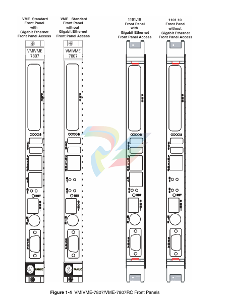
The VMIVME-7807/VME-7807RC provide front panel access for the PMC expansion
site, an optional Gigabit Ethernet port, one 10/100 RJ45 connector, one serial port,
SVGA, keyboard/mouse, the manual reset switch and the status LEDs. A drawing of
the VMIVME-7807/VME-7807RC front panels are shown in Figure 1-5. The front
panel connectors and indicators are labeled as follows:
• 10/100
• G1
• G2
• M/K
• COM1
•RST
• S
• SVGA
10/100 Mbit Ethernet connector
10/100/1000 Mbit Ethernet connector 1 (or LEDs) port 1
10/100/1000 Mbit Ethernet LEDs port 2
Mouse/keyboard connector
Serial Port
Manual reset switch
Status LEDs
Analog Video connector
The VMIVME-7807/VME-7807RC provide rear I/O support for the following: digital
video, Serial ATA, COM2. 3 and 4. IDE drive and two USB ports. These signals are
accessed by the use of an RTM such as the VMIACC-0586/ACC-0586RC and the
VMIACC-0590/ACC-0590RC, which terminates into industry standard connectors.
The front panel connectors, including connector pinouts and orientation, for the
VMIVME-7807/VME-7807RC are defined in Appendix A. Rear panel connections are
defined in the appropiate RTM Installation Guide. Contact Sales for compatible RTMs
offered by GE Fanuc Embedded Systems
The VMIVME-7807/VME-7807RC are Pentium M processor-based single board
computers compatible with modern industry standard desktop systems. The
VMIVME-7807/VME-7807RC therefore retain industry standard memory and I/O
maps along with a standard interrupt architecture. The integrated peripherals
described in this section (such as serial ports, USB ports, IDE drives, floppy drives,
video controller and Ethernet controller) are all memory mapped the same as
similarly equipped desktop systems, ensuring compatibility with modern operating
systems.
The following sections describe the standard features of the
VMIVME-7807/VME-7807RC
The VMIVME-7807/VME-7807RC provide DDR Synchronous DRAM (SDRAM) as
onboard system memory. Memory can be accessed as bytes, words or longwords.
The VMIVME-7807/VME-7807RC accept one 200-pin DDR SDRAM SODIMM along
with the optional solder-in 512MB onboard memory, for a maximum capacity of
1.5GB. The onboard DRAM is accessible to the VME through the PCI-to-PCI bridge
and is addressable by the local processor.
The PCI bus-based external devices include the Universe IID bridge, PMC site,
Ethernet controllers, FPGA and the GE Fanuc Embedded Systems connector. The
default BIOS maps these external devices to the PCI Interrupt Request (PIRQx) lines
of the 6300ESB I/O controller Hub. This mapping is defined in Table 2-1
The VMIVME-7807/VME-7807RC incorporate an SMSC Super I/O (SIO) chip. The
SIO provides the VMIVME-7807/VME-7807RC with two 16550 UART-compatible
serial ports, keyboard and mouse port. The keyboard and mouse ports are available
via the front panel using a standard PS/2 type connector. COM1 is accessed via the
front panel. COM2 is routed to the VME P2 connector.
COM ports 3 and 4 are also provided by the 6300ESB I/O Controller Hub and are
routed to the VME P2 connector.
The parallel IDE interface is provided by the Intel 6300ESB I/O Controller Hub. The
IDE interface supports two channels: primary and secondary. The secondary channel
is routed onboard to the optional CompactFlash socket. The primary channel is routed
out of the VME P2 backplane connector to an RTM which terminates into a standard
40-pin header. This channel can support a master and slave drive. The IDE interface
on the VMIVME-7807/VME-7807RC supports Ultra ATA/33. Ultra ATA/66 and Ultra
ATA/100 drives and automatically determines the proper operating mode based on
the type of drive used. In order to properly function in the Ultra ATA/100 mode, a
special 80 conductor cable must be used instead of the standard 40 conductor cable.
This cable is typically available from the Ultra ATA/100 drive manufacturer.
A Serial ATA Drive Interface is also provided by the 6300ESB I/O Controller Hub. The
Serial ATA port can be used alone or in limited conjunction with the parallel IDE
interface.
The network capability is provided by the Intel 82546EB for the VMIVME-7807 or the
Intel 82546GB for the VME-7807RC Ethernet Controller for Gigabit Ethernet and the
Intel 82551 10/100 Mbit Ethernet. These Ethernet controllers are PCI bus based and
are software configurable. The VMIVME-7807/VME-7807RC supports 10BaseT,
100BaseTX and 1000BaseT Ethernet.
10BaseT
A network based on the 10BaseT standard uses unshielded twisted-pair cables,
providing an economical solution to networking by allowing the use of existing
telephone wiring and connectors. The RJ45 connector is used with the 10BaseT
standard. 10BaseT has a maximum length of 100 meters.
100BaseTX
The VMIVME-7807/VME-7807RC also supports the 100BaseTX Ethernet. A network
based on a 100BaseTX standard uses unshielded twisted-pair cables and a RJ45
connector. 100BaseTX has a maximum length of 100 meters.
1000BaseT
The VMIVME-7807/VME-7807RC support 1000BaseT Ethernet using the Intel
82546EB for the VMIVME-7807 or the Intel 82546GB for the VME-7807RC dual
Ethernet controller. The interface uses shielded cables with four pairs of conductors,
along with an RJ45 connector on the front panel or routed to the VME P2 connector.
The Gigabit Ethernet is also available with the optional VITA 31.1 routed out of the
optional P0 connector
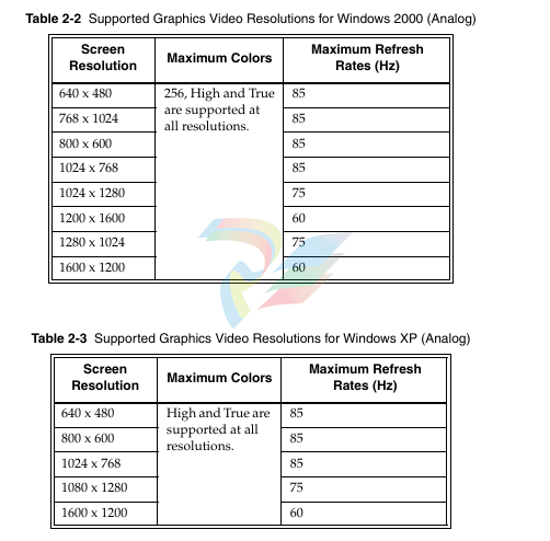
The SVGA port on the VMIVME-7807/VME-7807RC is controlled by the Intel
855GME Graphic and Memory Controller Hub (GMCH). The GMCH is hardware and
BIOS compatible with the industry SVGA and digital video standards supporting
both VESA high-resolution and extended video modes. Table 2-2 and Table 2-3 show
the graphics video modes supported by the GMCH video controller for analog
monitors
Digital Visual Interface (DVI)
2
The VMIVME-7807/VME-7807RC have a Digital Visual Interface that provides a
high-speed digital connection for visual data types that are display technology
independent. DVI is a display interface developed in response to the proliferation of
digital flat-panel displays. For the most part, these displays are currently connected to
an analog Video Graphics Array (VGA) interface and, thus, require a double
conversion.
The digital signal from the computer must be converted to an analog signal for the
analog VGA interface, then converted back to a digital signal for processing by the
flat-panel display. This inherently inefficient process takes a toll on performance and
video quality and adds cost. In contrast, when a flat-panel display is connected to a
digital interface, no digital-to-analog conversion is required.
DVI uses Silicon Image's PanelLink, a high-speed serial interface that uses Transition
Minimized Differential Signaling (TMDS) to send data to the monitor. The DFP and
VESA Plug and Display interfaces also use PanelLink. For this reason, DVI can work
with these previous interfaces by using adapter cables (depending on the signal
quality of the adapter.)
DVI also supports the VESA Display Data Channel (DDC) and the Extended Display
Identification Data (EDID) specifications. DDC is a standard communications channel
between the display adapter and monitor. EDID is a standard data format containing
monitor information such as vendor information, monitor timing, maximum image
size, and color characteristics. EDID information is stored in the display and is
communicated over the DDC. EDID and DDC enable the system, display and
graphics adapter to communicate so that the system can be configured to support
specific features available in the display.
DVI Connectors
The DVI connector has 24 pins that can accommodate up to two TMDS links and the
VESA DDC and EDID services. The DVI specification defines two types of connectors
(see Figure 1):
• DVI-Digital (DVI-D) supports digital displays only (used on the
VMIVME-7807/VME-7807RC)
• DVI-Integrated (DVI-I) supports digital displays and is backward compatible
with analog displays (not supported)
The VMIVME-7807/VME-7807RC use the DVI-I connector with a single TMDS link.
The DVI-I interface accommodates a 12- or 24-pin DVI plug connector or a new type
of analog plug connector that uses four additional pins, plus a ground plane plug to
maintain a constant impedance for the analog RGB signals
Dual Head Video
The VMIVME-7807/VME-7807RC are capable of driving two monitors at the same
time using the Intel 855GME GMCH. The graphics controller allows the use of one
digital monitor connected to the VMIACC-0590/ACC-0590RC or VMIACC-0586/
ACC-0586RC RTMs, routed out the rear I/O P2 connector. The second is a standard
SVGA monitor connected to the front panel of the VMIVME-7807/VME-7807RC,
using a standard DB15 connector.
Dual Head Setup Procedure:
1. Boot Windows 2000.
2. In the windows desktop right click.
3. When the menu appears, scroll down to the ‘Graphics Options’ and then click
on ‘Graphics Properties’. The Intel 82852/82855GM/GME graphics controller
properties menu will appear. From this menu you can choose the display mode
of choice.
The monitors can be displayed in several modes:
• Monitor Mode - In this mode only the SVGA monitor is displayed.
• Digital Mode - In this mode only the Digital is displayed.
• Dual Display Clone Mode - In this mode both the SVGA and the Digital
monitors are displayed, with the desktop the same on both monitors.
• Extended Desktop Mode - In this mode the two monitors are displayed as one
desktop.
4. After making your choice click ‘OK’ to apply the changes.
-
 Hirschmann RS20-1600M2T1SDAEHH03.1.02 Rail Switch
 -
 Hirschmann BRS30-24TX Industrial Rail Switch
 -
 Hirschmann RSPM20-4T14T1EV9HHS999.9.99 Managed Ethernet Switch
 -
 Hirschmann BELDEN RS40-0009CCCCSDAPHH09.0.14 / RS400009CCCCSDAPHH09014
 -
Hirschmann RS40 Rail Switch RS40-0009CCCCSDAE
-
 Hirschmann BELDEN RS30-0802T1T1SDAP / RS300802T1T1SDAP Fully Managed Layer 2 Compact Rail Switch
 -
 Hirschmann BELDEN RS20-0800M2M2SDAUHH / RS200800M2M2SDAUHH
 -
 Hirschmann EAGLE30-04022O6TT999SCCY9HSE3F Industrial Firewall Router Switch
 -
 Hirschmann RS20-1600T1T1SDAEHH09.0.14 RS20 Rail Mount Ethernet Switch
 -
 Hirschmann EAGLE0200T1T1TDDY90000HHE05.3.03 Industrial Security Router
 -
Hirschmann - BELDEN MIPP-AD-1L9P
-
 HIRSCHMANN RSPM20-4Z64Z6TV9HHS9 942 106-999 RAIL SAFETY SWITCH
 -
 HIRSCHMANN FIBEROPTIC MODULE FIP P/N: OZDFIPG3T
 -
 HIRSCHMANN RS20-1600M2M2SDAUHH Ethernet rack-mounted switch
 -
 HIRSCHMANN BELDEN RS20-0400T1T1SDAEHH04.0.01 / RS200400T1T1SDAEHH04001
 -
HIRSCHMANN MM2-4FXM3 MICE Media Module
-
HIRSCHMANN RS20-0800M2M2SDAE Industrial Ethernet Rail Switch
-
 Hirschmann RS20-2400T1T1SDAP / RS20-2400T1T1SDAPHH05.0.02
 -
 GE MLJ1005B010H00C MLJ Digital Synchromism Check
 -
 ALSTOM MICROTECH DX21-M2 Digital Excitation Controller
 -
HIRSCHMANN BRS20-1200ZZZZ-STCY99HHSES
-
 HIRSCHMANN MM3-4FXM2 MICE Media Module
 -
Hirschmann RSB20-0800T1T1SAABHH 8Port ENet Rail Switch RSB20
-
 Hirschmann MACH102-8TP Ethernet Switch
 -
 SAACKE DDZ-M marine steam pressure atomizer
 -
 SAACKE SKV-A marine rotary cup atomizer
 -
 SAACKE Seavis HMI05e
 -
 Kollmorgen MMC-SD-2.0-230 Servo Drive 100-240VAC 2KW 10A Output 3PH 100-240VAC
 -
 Kollmorgen Servo drive CR10550
 -
 Kollmorgen AKD-P01207-NACN-0054 Servo Driver
 -
 Kollmorgen S406M-CA-036 Servostar
 -
.png) Kollmorgen AKD-B02407-NAAN-0000 Digital Servo Drive
Kollmorgen AKD-B02407-NAAN-0000 Digital Servo Drive -
 Kollmorgen SERVOSTAR S406AM-CA Digital Servo Drive
 -
 KOLLMORGEN SERVOSTAR 603-AS SERVO AMPLIFIER_SERVOSTAR603AS_S60301
 -
Kollmorgen S700 Servo Controller (S70602-NANANA-NA)
-
 Kollmorgen MPK411 controller
 -
 KOLLMORGEN MMC-SD-1.3-460-D Smart Drive
 -
 KOLLMORGEN AKM21C-CKB2AA-00 / AKM21CCKB2AA00 Servomotor
 -
 BECKHOFF AX5106-0000-0200 | Digital Compact Servo Drives 1-channel
 -
 BECKHOFF C3620-0000 INDUSTRIAL COMPUTER (MOTORSHELVES)
 -
 Beckhoff EK1960-0000 TwinSAFE Compact Controller
 -
 Beckhoff C6930-0050 Control Cabinet Industrial PC
 -
 Beckhoff CP7711-0001-0030 Industrial Computer Detection
 -
 Beckhoff CX1001-0111 Embedded PC CPU Module
 -
 Beckhoff C6017-0020 | Ultra-compact Industrial PC
 -
 Beckhoff EK1322 | 2-port EtherCAT P junction with feed-in
 -
 Beckhoff CP2219-0010 Panel
 -
 BECKHOFF C6015-0020 ULTRA COMPACT INDUSTRIAL PC
 -
 BECKHOFF CX2030-0120/Standard CPU Module Embedded PC Windows PLC controller
 -
 Beckhoff CP7721-1090-0020 Panel PC
 -
 Beckhoff PC CPU Module CX5130-0175
 -
 Beckhoff C6920-0050 Control Cabinet
 -
 Beckhoff EL6631 EtherCAT 2-Port Communication Interface, Profinet RT Controller
 -
 Beckhoff CP6202-0001-0060 touch screen panel PC
 -
 Beckhoff CP3916-1002-0000 Multi-Touch Control Panel
 -
 Beckhoff EP1809-0021 | EtherCAT Box, 16-channel digital input, 24 V DC, 3 ms, M8Preferred type
 -
 Beckhoff CX8190 PLC Embedded Industrial PC Ethernet Controller
 -
 Beckhoff CX2100-0914 Power Supply for External
 -
 Beckhoff Automation CP6906-0001-0000 HMI
 -
 Beckhoff EP7342-0002 Module
 -
 Beckhoff CX1020-0112 / CX1100-0910 / CX1020-N010 / CX1100-0003 Windows CPU
 -
 Beckhoff EP7211-0034 EtherCAT Box 1 Channel Motion Interface
 -
 Beckhoff C6240-0030 Control cabinet Industrial PC
 -
 beckhoff motherboard CB1052-0004 CB1052-0004
 -
 Beckhoff AX2006-AS Servo Drive / Variable Frequency Drive
 -
BECKHOFF CP6207-0001-0020 NSMP
-
 Beckhoff C6930-1142-0060 Industrial Computer
 -
 Beckhoff FC7501-0000 interface card
 -
 Beckhoff CX5140-0175 Embedded PC PLC CPU CX5140 Industrial Controller
 -
 Beckhoff CP7802-1100-0010: High-End IP65 Control Panel with DVI/USB Extended Interface
 -
BECKHOFF CP3716-1058-0010 CONTROL PANEL
-
 Beckhoff AX8108-0000 Single-Axis Module
 -
 Beckhoff CU8851-0000 | USB extension, USB Extended 2.0 receiver box
 -
Beckhoff C6017-0030 | Ultra-compact Industrial PC
-
 Beckhoff CX1001-0120/CX10010120.cx1000-n001.cx1000-n000 System Overview
 -
 Beckhoff CPU Module CX5140-0155/4GB CPU Module
 -
 Beckhoff CP6533-0001-005: Built-in Panel PC with High-Definition Multi-Touch Control
 -
 Beckhoff EL5042 | EtherCAT Terminal, 2-channel encoder interface, BiSS® C
 -
 Beckhoff C6920-1080-0040: Premium Control Cabinet Industrial PC
 -
 Beckhoff C6920-0060 | Control cabinet Industrial PC
 -
 Beckhoff Embedded-PC CX5010-1121
 -
 Beckhoff CB3050-0010 Mainboard Motherboard
 -
 Beckhoff PLC module CX1020-0000 Basic CPU module (service phase)
 -
 Beckhoff CP7812-1056-0010 15" Multitouch Display Control Panel
 -
 Beckhoff CX5120-0115 /2GB Controller Module
 -
 Beckhoff CP7201-1000-0000 Industrial Panel PC
 -
 Beckhoff Servo Motor AM8061-0JH1-0000
 -
 BECKHOFF CP6503-0001-0050 Built-in Panel PC
 -
Beckhoff CP3919-0010 Display G190ETN01.2 19" PCT V04. Multi-touch Control Panel
-
 Beckhoff CX5110-0112-9020/000368201 Embedded PC Intel Atom Processor
 -
 Beckhoff AX8206-0000 Dual-Axis Module
 -
Beckhoff Nail Operating Terminal CP7032-1031-0010
-
Beckhoff AM8042-0EH1-0000 Servomotor 4.10 Nm (M0), F4 (87 mm)
-
 Beckhoff EK9300 Beckhoff CPU Module
 -
Beckhoff CP3224-0020 Multitouch-Panel-PC
-
 Beckhoff CP2712-0000 12.1" 24VDC Touch Screen WMD0
 -
 BECKHOFF CX5240-0195 / 0000289234 Embedded PC 40 GB CFast Card
 -
 Beckhoff CP6932-1000-0000 Control Panel
 -
 BECKHOFF CX5120-0121 PLC Module
 -
 Beckhoff EL3218 | EtherCAT Terminal, 8-channel analog input
 -
Beckhoff C6640-0050 | Control cabinet Industrial PC
-
 Beckhoff Cx5130-0120/4GB Embedded-PC
 -
 BECKHOFF CX2030-0122 PLC PROCESSOR
 -
 BECKHOFF CX5020-0122 Controller Module
 -
 Beckhoff CP3915-0000 Multitouch Panel
 -
 BECKHOFF EL3014 | EtherCAT Terminal
 -
 BECKHOFF Industrial Computer c6920-1057-0030
 -
 Beckhoff CX5130-0141/4GB CX5130-0141 Embedded PC
 -
 Beckhoff C6240-1052-0040 4-086-06-3073 Industrial Computer
 -
 Beckhoff CX5140-0135 /4GB High-Performance Embedded Industrial PC
 -
 Beckhoff C6515-1001-0000 Industrial PC
 -
 Beckhoff AX5103-0000-0200 - Digital Compact Servo Drives
 -
 Beckhoff CX2030-0130-1003/4GB Basic CPU module
 -
 Beckhoff AX8620-0000 Power Supply Module
 -
 Beckhoff CX9020-0111 module with
 -
 Beckhoff EL7332 PLC Module
 -
 BECKHOFF CP7709-0001-0020 HMI
 -
 Beckhoff CX5120-0155/2GB Embedded PC
 -
 BECKHOFF CP7037-1037-0010 OPERATOR INTERFACE TOUCHSCREEN
 -
 Beckhoff EK9000 | ModbusTCP/UDP Bus Coupler
 -
 Beckhoff Touch Panel Screen CP6020 -0000-0000
 -
 Beckhoff CX2020-0121 Module FAST Shipping
 -
 Beckhoff CX2030-0125 Basic CPU Module
 -
 Beckhoff CP3918-0000 Multi-Touch 18.5" Control Panel
 -
 Automotion LC4A00010 DC BL Motor Control, ATS, Sub Assy, SCP, 115VAC,
 -
 500T-115VAC - VAS ENGINEERING - DORIC 500 SERIES DIGITAL TEMP INDICATOR
 -
 Honeywell X-DCS2000/EN Digital Integrated System Manager 50/60Hz 100-240V #4
 -
 Kollmorgen S60600 Servostar600 606-Fan 4 kVA, 6 A, 3 X 230 - 480 V


