
Woodward 505 Digital Controller For steam turbineses
8200-1300. 8200-1301. 8200-1302
505 Digital Controller
For steam turbines
8200-1300. 8200-1301. 8200-1302
This chapter provides a brief introduction to other Woodward devices that are easy to integrate with the 505. By understanding the peripheral devices
The functions of the equipment can help you better understand the overall control configuration.
Some of these devices CAN communicate with each other via a digital communication link (Ethernet or CAN, depending on the product)
Connect 505. Through this link, the 505 monitor will allow users to monitor many things from this external device
Signal and status LED. In many cases, these connections allow the 505 to receive the required input signals, for example
Such as KW load signals or synchronization or load distribution bias signals. This eliminates the need to wire these signals to typical ones
The demand for I/O channels, or digital signals can be used as redundant/backup signals for hardwired signals.
Devices supported within the 505 control application will be identified as the "Woodward Link" identifier
All the equipment covered in this section is manufactured or supported by Woodward. Peripheral devices manufactured by other companies are acceptable
Used in conjunction with 505 to perform the following functions, however, they should be confirmed to be compatible with 505 before system operation

And the compatibility of the application.
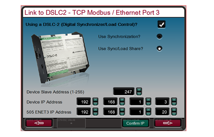
When DSLC-2 is connected to the 505 controller, it can be used together with a generator to accurately detect three phases
The output power of the RMS generator is synchronized with the actuator generator circuit breaker. Other configurable DSLC-2 feature packs
Including generator load distribution, VAR or power factor control, process control and basic load control.
Woodward 505 digital governor for steam turbines with single or split actuators
This is a "Woodward Link" device.
To enable the Woodward Link feature, select the selection box on the above screen, enter the slave address and DSLC-2 Settings
The prepared IP address. The above figure shows the factory default IP addresses of the DSLC-2 and Ethernet port 3 of the 505.
Once the Ethernet port 3 of the 505 and the network port B of the DSLC-2 are connected with an RJ45 cable
Next, these Settings will allow the two products to communicate automatically.
Once this configuration is completed, DSLC-2 can provide synchronous speed bias signals and synchronous/load distribution bias signals
And the KW output of the generator. The radio buttons on the screen allow users to select the desired functions. Through this chain
The KW valued by the path can be used as an auxiliary KW input signal and is a pre-configured analog input for the KW input
Entry passage.
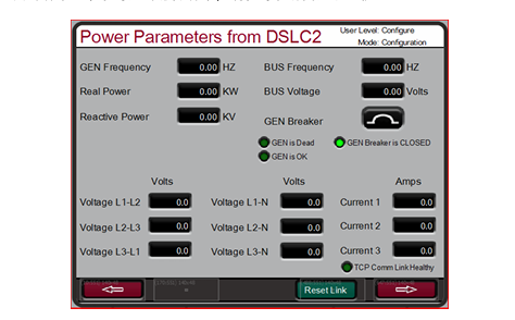
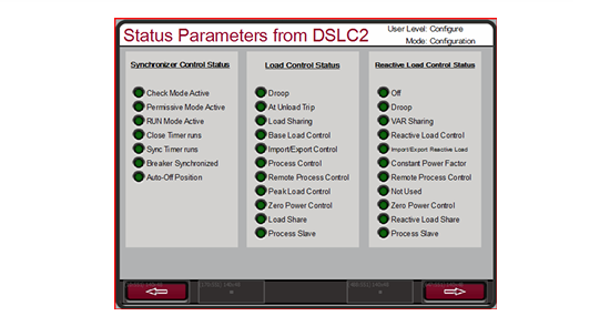
The following screen shows the available service screens, which can now be accessed for monitoring DSLC-2.
VariStroke-II is a linear electronic-hydraulic actuator designed to provide control valves for operating steam turbines
Or the linear actuator of the valve frame. This actuator can be directly networked with the 505 controller to reduce
Low system complexity and wiring requirements.
To enable the Woodward Link feature, select the selection box on the above screen to enable CAN1 Link and confirm
Use the VariStroke II actuator and then enter the device ID. If an analog (4-20 mA) requires a letter
If the signal is about to be connected to the CAN link and VariStroke, then select the desired function for this signal (recommended)
AI as a backup. Finally, select the steam inlet valve being controlled (for most applications, it is an HP requirement).
This is a "Woodward Link" device.
The MFR 300 is a multi-functional generator protection relay used for detecting and protecting small generators. This is quite a lot.
The functional protection relay integrates all generator protection functions in a common device, reducing the overall system
Installation replicability and cost.
This is a "Woodward Link" device.
The LS-5 series protection relay integrates the synchronization, power detection and protection functions of the generator circuit breaker into one. This assumption
It is designed to function in conjunction with a prime mover controller similar to the 505 to allow for accurate generator operation
Control and provide the required generator protection.
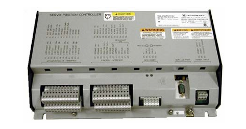
Servo mechanism Position Controller (SPC
The servo mechanism position controller (SPC) can be used to connect the 505 digital controller to the existing valve actuator
Or integrate actions or Woodward actuators that are not directly compatible with 505.
The actuator output of 505 is capable of driving a ratio of 4-20 mA or 20-160 mA (up to 200 mA)
The signal enters an actuator coil. These actuator output signals represent the equivalent of the desired valve position (ratio)
For example, the required signal. If the actuator or servo mechanism assembly of the steam turbine requires a different drive signal,
Or control actions (integrated with invalid Settings), a SPC or equivalent device must be used.
Woodward servo position Controller (SPC) accepts 4-20 mA actuation proportional to the desired valve position
The driving signal of the actuator is activated, and a servo mechanism assembly is correspondingly installed. Woodward SPC is capable
Drive proportional or integrated servo mechanism assemblies with single-pole execution up to 0-400 mA or dual-pole execution of +400 mA
The institution requires signals.
SPC comes with a user-friendly software interface program that allows users to configure the unit to the desired Settings.
Check the complete details of the types of actuators that SPC can connect to in the SPC manual. Below are 505 and
An example of how SPC can be applied to integrated servo mechanism valves. SPC can also handle many feedback devices
Transformation.
The actual power sensor is used to detect the actual power generated by the generator or the actual power flowing through the connecting lines.
Woodward's actual power sensor detects three-phase voltage and three-phase current, and compares the relationship between voltage and current of each phase.
And it generates a 4-20 mA output proportional to the actual power.
Woodward produces two types of actual power sensors. The first type of actual power sensor is designed for
Detect the power flow in only one direction (only 0 to +5 A CT current), and output a ratio of 4 to 20
mA signal. This type of actual power sensor is designed for and should be used to detect the power output of generators
Out. There are many different actual power sensors of this type. Some functions of the optional actual power sensor include
VAR detection, load distribution, 0-1 A CT current detection, and combinations of multiple functions. Please consult Wood.
Get the recommended actual power sensors suitable for your application from a Wards-certified distributor or Woodward factory.
The second type of actual power sensor produced by Woodward is designed to detect through busbar-to-busbar connection lines
Power flow. This actual power sensor (8272-726) detects A CT current ranging from -5 A to +5 A to allow it
Output power flows representing two directions. This actual power sensor provides a 4-20 mA power indication output
Output the signal, with 12 mA representing 0 power current. It is recommended to use this actual power sensor for detection only if it passes
The power current of a connecting line. It is required that this actual power sensor or equivalent equipment detect the input and output power of the power plant
Rate.
Woodward's actual power sensors have terminals labeled "Output" and terminals labeled "KW Read". “KW
The "read" terminal provides a 4-20 mA signal proportional to the actual power, which is used in parallel by the 505 controller
Compatible with it. Therefore, the actual power sensor labeled "Output" is for Woodward's 2301 type control
The device is designed and only compatible with it.
The output of the actual power sensor produced by Woodward has a 2.5Hz low-pass filter (with a delay of 400 ms)
It is used to filter out the high-frequency noise typically generated in the switch-type environment. Therefore, if another one is used
The power converter of this supplier should be verified to have similar filtering criteria before being applied together with 505.
For more information about Woodward's actual power sensors, please refer to Woodward Manual 82018.
Engine Generator Control Package/Load Distribution (EGCP-3 LS)
The Woodward EGCP-3 LS controller is a generator load-based microprocessor designed to work with Wood
Ward speed controllers and automatic voltage regulators are used together in three-phase AC generators. EGCP-3 LS is one
Synchronizer, one load controller, one dead busbar closure system, one VAR/PF controller, one overpass
The process controller, power and energy measurement, and protection relay are integrated into one.
The EGCP-3 LS has a keyboard and two 4-wire display panels on the chassis installed in the front cabinet. The display screen can
It is used to configure and set the controller according to the specific on-site requirements. The display screen can also be used for normal operation services to monitor
Depending on the operation and check the alarm data. All the functions performed on the front panel and all the parameters monitored can be accessed through three
Serial port obtained. These ports can be configured to use Woodward Watch Window software. This is one
An external HMI communicates with Modbus or Servlink DDE software.
The 505 configuration can be configured to use EGCP-3 LS only as a synchronizer, or as a synchronizer and load control
"Device. The EGCP-3 LS provides phase matching or slip frequency and is connected to the unit's automatic voltage regulator in parallel
Match the voltage before connection. It is connected to the 505 through a speed bias signal to control the generator frequency and phase
position. When configured to use EGCP-3 LS only as a synchronizer, 505 must be configured to be configured via analog input
Receive the EGCP-3 speed bias signal and enable this input through contact input or function keys.
When used as a synchronizer and load controller, EGCP-3 LS performs automatic synchronization in accordance with EGCP-3
The operation mode controller load. EGCP-3 LS can be set for basic load, load distribution, and remote load
The setting, or process control mode, depends on the configuration and system conditions.
The load distribution mode of EGCP-3 LS is used to distribute loads to those using EGCP-3 LS and tied to the same isolation busbar
Any other units of the line. When connected in parallel to the power grid, this mode is used together with EGCP-3 MC to allow
The EGCP-3 MC controls the frequency or load of the power plant depending on its operating status.
The remote load setting mode of EGCP-3 LS allows a remote 4-20 mA signal to set the load. EGCP
The process control mode of 3LS allows for the control of any process directly related to the generator load.
After synchronization, it can be obtained by EGCP-3 LS (via 505 synchronization/load input) or by the internal speed of 505 /
The load setting value controls the load of the unit. When configuring the synchronous/load input, the position of the contacts of the power grid circuit breaker is open
Select the unit load control through the internal load setting values of EGCP-3 LS or 505.
Once the generator is synchronized with the EGCP-3 LS software load, the unit to the load setting has an operating mode (base load,
Load distribution and process control have been determined. Upon receiving the instruction, EGCP-3 LS can also perform software unloading on the unit
Negative, simultaneously issue a circuit breaker disconnection command at a set power level.
The PowerSense board receives PT and CT inputs for the generator and busbar to be used within the system controller
The parameters were calculated using EGCP-3. The algorithm used is based on IEEE 1459-2000. For the generator and busbar
The following parameters are provided: Hz, Vac, Amps, W, VA, VAR, PF, phase, voltage modulation, and electricity
Current regulation, negative phase sequence voltage, negative phase sequence current. In the 4-20mA analog output, optional: synchronous oscilloscope,
Generator measurement, main line measurement.
EGCP-3 LS is equipped with the following busbar protection:
Overvoltage/undervoltage (59.27)
Overfrequency/underfrequency (81O, 81U)
Directional (forward/reverse) power (32) *
Negative sequence overcurrent (46
Negative sequence overvoltage (47
Phase overcurrent (51) *
Voltage limiting phase overcurrent (51V) *
Directional VAR
Phase current imbalance (46
The EGCP-3 LS is equipped with the following generator protections:
Overvoltage/undervoltage (59.27)
Overfrequency/underfrequency (81O, 81U)
Directional (input/output) power (32) *
Negative sequence overcurrent (46
Negative sequence overvoltage (47
Phase overcurrent (51) *
Directional VAR
Phase current imbalance (46) *
The rotational speed/frequency is mismatched
Apply 505 in conjunction with redundant I/H or I/P converters
505 can be applied in simplex or redundant actuator systems. For redundant actuator applications, actuators
Channel 1 is configured to lead for HP instructions, and Channel 2 is configured for zero-bias HP2 requirements. this
It will provide the full current from the two actuator drive circuits to the driven device
The selection between the output signals of the converter can be accomplished by using an edge valve or a solenoid delivery valve. Converter status (I/H
Or I/P and pressure feedback signals can be selectively configured into the 505. If necessary, the relay output can be configured
Switch between the outputs of the converter. Manual switching between converters can be achieved through discrete input and Modbus
Or use the PC interface command to start. The automatic switching between converters is carried out by 505 based on drive failure and conversion
The feedback signals of the device status, the output pressure of the converter and the input pressure of the servo mechanism are provided.
Functional details
The use of a dual-actuator configuration can provide redundancy up to the actuator level. A typical redundant I/H (or I/P) system
The milliampere output of the 505 actuator will be converted into the corresponding hydraulic (or pneumatic) pressure of the positioning servo mechanism cylinder
Force. Both converters supply the appropriate pressure to position the steam valve as required by the controller. One of the conversions
One will control the valve position requirements, while the other will be in standby mode. The selection between the output signals of the converter can be made using edges
It can be accomplished by using a valve or a solenoid conveyor valve. The edge valve will select the higher pressure output of the two converters, the solenoid transfer valve
Then select the output of one converter and switch between the two converters based on the relay command from the 505 controller
Change. Either type of valve can be used. Refer to the conveyor valve section for the respective advantages of the two types of valves
Information on strengths/weaknesses.
The converter status (I/H or I/P) and pressure feedback signals should be configured into 505 because of the automatic between converters
Switching is provided and handled by the states of these signals. If necessary, a relay output can be configured (configuration)
It is a relay that serves a control function to switch between the outputs of the converter.
Automatic switching is based on configured I/O (see available I/O options). If a converter is configured, then
If the input is discrete, it is used for fault alarm and automatic switching.
Properly installed valves allow for online converter replacement.
For more information about Woodward's redundant CPC products, refer to Manual 26448 and consult your sales representative
Represent all CPC products.
This chapter is designed to provide users with a concept of the capabilities of the 505 electronic controller and how to apply it in the system
They. Typical applications are all presented in the chart, and their functions are also explained. Each application is equipped
Set and start/run mode annotations to assist application configurators in configuring 505 for their own applications. "Basic"
The device connection is displayed in each application drawing to allow for an understanding of how these devices are connected to the 505 and expanded
Show your abilities.
Speed/Load PID
The speed PID can be controlled and limited
Unit speed/frequency
Unit load
When operating in a solitary network, the speed PID of 505 can be used to control the speed/frequency of the unit and is parallel to the infinite bus
When the power grid is connected in parallel, it can be used to control the load of the unit. The speed PID can be configured to output signals through its actuator
The unit load is detected by the 4-20mA analog input signal from the generator power sensor or the number. When configured to be on
When detecting and controlling the generator load through analog input, what is detected and controlled is the real unit load. By making
The control is carried out by the generator load signal, and any difference in the intake or exhaust pressure of the steam turbine is detected and obtained
Compensation, thereby providing true load control.
The combination of the speed PID and its set value limit allows this PID to limit the unit load. When used as a load limiter for the unit
At that time, it is recommended to configure the 505 to only detect and control the actual generator load. If 505 is applied to soft power
net
Due to the large variations in grid frequency, it is recommended to use auxiliary PID rather than speed PID to limit the load of the unit.
Auxiliary PID
The auxiliary PID of 505 can be configured to control or limit:
Steam turbine inlet pressure
Steam turbine inlet flow rate
Steam turbine exhaust pressure
Steam turbine exhaust flow
Generator power output
Input/output power of power plants or lines
Process temperature
Inlet pressure of the compressor
Inlet flow rate of the compressor
Outlet pressure of the compressor
Outlet flow rate of the compressor
Any process parameters related to the unit load, intake steam pressure/flow rate, exhaust steam pressure/flow rate (depending on the configuration
"Place
The auxiliary PID of 505 can be used as a limiter or controller (enabled and disabled according to instructions). When the configuration is the limit
When making the device, the output of this PID is a low-signal selection compared to the output of the rotational speed PID. This configuration allows for auxiliary PID
Limit the load of the unit based on the detected parameters.
When the auxiliary PID is configured as a controller, it must be accessed through the 505's front panel, contact input, or Modbus
Enable and disable the given instructions. After setting it up in this way, when the auxiliary PID is enabled, the speed PID is disabled
Use and track the output of the auxiliary PID.
To control or limit any of the listed parameters, the 505 must be configured to accept an auxiliary analog input representing the parameter level
Input signal. The exception to this principle is that when controlling or limiting the generator load, the auxiliary PID can be configured to enable
Use and share the KW/ unit load with the speed PID.
Cascade PID
The cascade PID of 505 can be configured for control:
Steam turbine inlet pressure
Steam turbine inlet flow rate
Steam turbine exhaust pressure
Steam turbine exhaust flow
Generator power output
Input/output power of power plants or lines
Process temperature
Inlet pressure of the compressor
Inlet flow rate of the compressor
Outlet pressure of the compressor
Outlet flow rate of the compressor
Any process parameters related to the unit load, intake steam pressure or exhaust steam pressure (depending on the configuration
The cascade PID of 505 can be used to control any of the listed parameters. This PID must pass in front of 505
Enable and disable based on the board, contact input or instructions given by Modbus.
Cascade PID and speed PID cascade are used to change the speed/load of the unit. By directly locating the speed PID
The set value, cascade PID can change the unit speed/load to the controller input parameter. This configuration allows for up to two
Disturbance-free switching is performed between two control modes (speed/load and cascade).
Sample application
The sample applications in this chapter will not demonstrate every possible control configuration or combination. However, these examples can also serve as references
Examine to apply any control combinations or parameters that are not listed or displayed. Apply a control that is desired but not displayed
To set parameters or combinations, refer to one or more typical application configurations that are displayed and similar to the desired control configuration, and then
Replace the displayed control parameters with the desired ones.
To apply a desired but not displayed control parameter or combination, refer to one or more displayed ones that are similar to what you want
The typical application configuration of the control configuration, and then replace the displayed control parameters with the desired control parameters.
Example - To configure 505 to perform a steam turbine exhaust pressure limiting function, use Example 1. "with steam turbine
The application of "pump or compressor outlet pressure control with machine inlet steam pressure limit" is used as a reference. Refer to this example and use exhaust steam
Replace the intake pressure and ignore any specified program Settings to control the outlet pressure of the pump or compressor.
The examples shown in this chapter are summarized as follows:
Example 1: Outlet pressure control of pumps or compressors with inlet steam pressure limits
Example 2: Intake steam pressure control with automatic synchronization and generator power limit
Example 3: Exhaust pressure control with input/output power limits
Example 4: Input/output power control of power plants with DRFD servo mechanism interface
Example 5: Intake steam pressure control with synchronous load distribution in island mode
Example 6: Input/Output power control of power plants with synchronous load distribution in island mode
Example 7: Induction generator control
This is a typical example of a pump or compressor application. With this application, the 505 is configured to normally control the pump/compressor
The outlet pressure is controlled, and the speed control valve position is limited based on the low steam inlet pressure of the steam turbine. Both the auxiliary mode and the cascade mode are used
This sample application. Other applications may or may not use the functions shown in Figure 3-1 and all of the following.
With this application, the pump/compressor outlet pressure is controlled within 505 through a cascade controller. Due to export pressure
To obtain control, which usually affects many other power plant processes, a power plant distributed control system (DCS) can be used
Monitor the process conditions of the power plant and set the positions of cascade setting values. This can be achieved through Modbus communication, discrete elevation and
Lower the instruction or execute it with an analog set value signal.
This application requires a control function restriction type to help maintain the steam intake main pipe when there is a problem with the system main pipe
Pressure. Because the auxiliary PID is the only controller with this capability, it is used according to the low steam turbine intake
The pressure setting is used to detect the steam inlet pressure of the steam turbine and limit the position of the speed control valve.
If a distributed control system of a power plant is used to detect by locating the loads (load distribution) of multiple pumps or compressors
To measure and control a process, this DCS can simulate an input with 505 through a configured remote speed setting value
Connect directly. This enables DCS to control power plants and systems by directly and simultaneously changing the rotational speeds of multiple pumps or compressors
Monitor and compensate under the unified conditions.
All 505 PID controller set values (speed, assist, cascade) can be increased or decreased through configuration
The contacts, configured 4-20mA input, Modbus instructions, or 505 service panel can be changed.
-
 HIRSCHMANN MSM20-M2M2M2M2SY9HH9E Ethernet media modul
 -
 HIRSCHMANN SPIDER-PL-20-05T1999999TWVHHHH Industrial Ethernet Rail Switch
 -
 Hirschmann SPIDER-PL-20-07T1M2M299TWVHHHH Industrial ETHERNET Rail Switch
 -
.png) Hirschmann (Belden) RS20-1600M2M2SDAEHC09.1.00 DIN-rail managed industrial Fast Ethernet switch
Hirschmann (Belden) RS20-1600M2M2SDAEHC09.1.00 DIN-rail managed industrial Fast Ethernet switch -
 Hirschmann (Belden) RS30-1602O6O6TDAPHC09.1.00 DIN-rail managed industrial Ethernet switch
 -
 Hirschmann (Belden) RS30-2402O6T1SDAPHH09.0.13 DIN-rail industrial Ethernet switch
 -
Hirschmann (Belden) SPIDER-PL-20-04T1S29999TY9HHHH Ethernet DIN-rail switch
-
 HIRSCHMANN RS20-1600T1T1SDAUHX Switch
 -
 HIRSCHMANN BRS42-0012OOOO-SPCZ99HHSES industrial switch
 -
 Hirschmann RS20-0800S2S2TDHPHH09.0.14 Fast Ethernet DIN rail switch.
 -
 HIRSCHMANN MM20-Z6Z6M2M2SAHH Hybrid Fast Ethernet Media Module
 -
 HIRSCHMANN MM20-Z6Z6T1T1SAHH hot-swappable hybrid Fast Ethernet Media Module
 -
 HIRSCHMANN MM20-P9P9T1T1SAHH Hybrid Fast Ethernet Media Module
 -
 HIRSCHMANN MM20-M4T1T1T1SAHH Hybrid Fast Ethernet Media Module
 -
 HIRSCHMANN MM20-M4M4T1T1SAHH Hybrid Fast Ethernet Media Module
 -
 HIRSCHMANN MM20-M2M2M2M2SZHH Ethernet media module
 -
HIRSCHMANN MM20-M2M2M2M2SAHH Ethernet media module
-
 HIRSCHMANN MM20-T1T1T1T1EBH 4-port Fast Ethernet Copper Cable Media Module
 -
HIRSCHMANN MM20-T1T1T1T1SAHH 4-port Fast Ethernet Copper Cable Media Module
-
HIRSCHMANN MM20-T1T1T1T1SAHH 4-port Fast Ethernet Copper Cable Media Module
-
 HIRSCHMANN MM20-Z6Z6EBH Hot-swappable fast Ethernet media module
 -
 HIRSCHMANN MM20-Z6Z6SAHH Ethernet media module
 -
HIRSCHMANN MM20-Z6Z6Z6Z6EBH Industrial Media Module
-
 MSM40-T1T1T1TZ9HH9E99.9.99 HIRSCHMANN Switch
 -
 HIRSCHMANN MS20-0800SAAEHC / MS20-0800SAAEHC0 8-port modular Layer 2 management Ethernet switch
 -
 Hirschmann RSPM20-4T14T1SZ9HHS9 Switch RSPM20-4T14T1SZ9HHS9
 -
 HIRSCHMANN RS20-1600M2M2SDAEHH09.1. RS20/30/40 Managed Switch configurator
 -
HIRSCHMANN RS20-1600M2M2SDAEHX09.0.00 Ethernet switch
-
 HIRSCHMANN BELDEN SPIDER-PL-20-07T1M2M299TY9HHHH / SPIDERPL2007T1M2M299TY9HHHH
 -
HIRSCHMANN MM3-1FXS2/3TX1 Switching Board Module
-
 HIRSCHMANN RSPE30-24044O7T99-ECCP999HHSE2A08.1.00 Industrial-grade fanless management-type Ethernet switch
 -
 HIRSCHMANN RS30-1602OOZZSDAEHC09.1.00 DIN-rail-mounted managed Layer 2 Ethernet switch
 -
 HIRSCHMANN MACH104-20TX-F Managed 24-port Full Gigabit 19" Switch
 -
 HIRSCHMANN Switch RS20-0800M4M4SDAE
 -
Hirschmann RS30-1602O6O6SDAEHH09.1. Management-type Ethernet switch
-
 Hirschmann RS30-1602OOZZSDAEHC09.0.10 Open rack-style Ethernet switch
 -
 HIRSCHMANN RSPE30-24044O7T99-SCCV999HHSI2SXX.X.XX High-Availability Seamless Redundancy
 -
HIRSCHMANN RSPE30-24044O7T99-SCCZ999HHSE2A DIN-rail Ethernet switch
-
HIRSCHMANN MM2-4TX1-EEC switch
-
HIRSCHMANN MSM40-T1T1T1T1TZ9HH9E99.9.99 Module
-
 HIRSCHMANN RS20 Rail Switch RS20-0400S4T1SDAEHC07.1.01
 -
 HIRSCHMANN M4-FAST8-SFP Fast Ethernet media module
 -
 HIRSCHMANN RS20-0400M2T1SDAP Managed Fast-Ethernet-Switch
 -
 HIRSCHMANN BELDEN SPIDER II 8TX/1FX EEC Industrial Ethernet Rail Switch
 -
HIRSCHMANN MM3-2FXS2/2TX1
-
 HIRSCHMANN RS2-4TX/1FX EEC Industrial Ethernet Rail Switch
 -
 RS30-0802O6O6SDAEHC09.0.10 HIRSCHMANN Switch
 -
 HIRSCHMANN m4-8TP-RJ45 Ethernet Media Module
 -
 HIRSCHMANN MSP30-24040SCZ9URHHE3A switch
 -
 Hirschmann rack MS30-1602SAAPHC
 -
 HIRSCHMANN RS2-FX/FX Industrial Switch Module
 -
Rs1txfx - Hirschmann - Rs1-Tx/Fx Rail Switch
-
RS20-0800S2S2SDAEHC09.1.00 HIRSCHMANN Commutator
-
 Hirschmann EAGLE20 TX/TX Industrial Security Router
 -
 Hirschmann SPIDER-SL-20-04T1S29999SY9HHHH Industrial Switch
 -
 HIRSCHMANN MAR1040-4C4C4C4C9999SMMHRHHXX.X. Gigabit Ethernet Switch configurator
 -
 Hirschmann MAR1040 Industrial Switch
 -
 HIRSCHMANN BELDEN RS30-1602O6O6SDAE
 -
Hirschmann RS20-1600M2M2SDAUHC Ethernet DIN rail switch
-
 HIRSCHMANN OCTOPUS 24M industrial switch
 -
 HIRSCHMANN RS20-1600T1T1SDAE Management-type Ethernet switch
 -
 HIRSCHMANN RS20-1600T1T1SDAUHH industrial switch
 -
HIRSCHMANN RS20-0800M2M2SDAPHC09.0.04 switch
-
 Hirschmann MR 8-03 24V DC Industrial Modular Bridge/Router
 -
 HIRSCHMANN RS20-0400M2T1SDAPHC08.0.01 Managed Switch
 -
 MACH1130 Hirschmann Industrial Switch
 -
 HIRSCHMANN 943824-002 SPIDER 5TX Industrial Ethernet Switch
 -
 HIRSCHMANN RS30-0802O6O6SDAEHC09.1.00 Managed Industrial Switch
 -
 HIRSCHMANN RS20-0400M2M2TDAEHC04.0.01 Industrial Switch
 -
 HIRSCHMANN BRS20-0600Z6Z6-STCZ99HHSES Industrial Switch
 -
 HIRSCHMANN MACH104-20TX-FR-L3P Industrial Ethernet Switch
 -
 HIRSCHMANN RS40-0009CCCCEDBPHH06.0.01 Industrial Switch
 -
 HIRSCHMANN RS2-3TX/2FX EEC Industrial Ethernet Switch
 -
 Hirschmann MACH 1020/1030 Fast/Gigabit Rack Mount Switches
 -
HIRSCHMANN RS20-0800M2M2SDAPHC09.0.14 Industrial Switch
-
 HIRSCHMANN RS20-1600T1T1SDAEHC09.0.04 Industrial Switch
 -
 HIRSCHMANN RSB20-0800T1T1EAABHH Industrial Switch
 -
 HIRSCHMANN MACH4002-48+4G-L3E Industrial Backbone Switch
 -
 HIRSCHMANN RS20-0400S2T1SDAE Industrial Managed Switch
 -
HIRSCHMANN RS20-0800S2T1SDAUHC Industrial Switch
-
 HIRSCHMANN RS20-2400S4S4SDAEHC09.0.14 industrial switch
 -
 HIRSCHMANN OS20-001200T5T5T5- TBBZ999HHNE3S 08.1.00 industrial switch
 -
HIRSCHMANN OS20-001200T5T5T5- TBBZ999HHNE3S 08.1.00 industrial switch
-
 HIRSCHMANN RS40-0009CCCCSDAEHH09.0.14 switch
 -
 Hirschmann RS20-1600T1T1SDAUHC Management-type Ethernet Switch
 -
 Hirschmann M1-8SFP Switche
 -
Hirschmann Industrial Ethernet Ruggedized Switch MACH1000 Family
-
 Basler Electric, Solid State Protective Relay, BE1-60
 -
BASLER ELECTRIC SR4A-2B15B3A Static Voltage Regulator
-
.png) BASLER ELECTRIC EXCITER DIODE MONITOR EDM-200
BASLER ELECTRIC EXCITER DIODE MONITOR EDM-200 -
.png) BASLER ELECTRIC DECS125-15-B2C5 DIGITAL EXCITATION CONTROL SYSTEM V 2.0.9
BASLER ELECTRIC DECS125-15-B2C5 DIGITAL EXCITATION CONTROL SYSTEM V 2.0.9 -
 BASLER ELECTRIC BE1-851 OVERCURRENT PROTECTION RELAY MECHANISM
 -
 Basler Electric BE1-51A / BE151A
 -
 Basler Electric BE1-40Q Loss of Excitation Relay
 -
 Basler Electric BE1-87G Variable Percentage Differential Relay
 -
 Basler Electric BE1-11 Protection System I5A3M2P2N0EA00
 -
 BASLER ELECTRIC DECS-200-1C Digital Excitation Control System
 -
 Basler Electric / Kohler BE1-11g Generator Protection Relay G5A3M2J2N0E000
 -
BASLER ELECTRIC DECS125-15 DIGITAL EXCITATION CONTROL SYSTEM
-
 BASLER ELECTRIC BE1-951 OverCurrent Protecton System
 -
Basler Electric DECS-200-1L Digital Excitation Control System
-
 Basler Electric DGC-2020HD-5NS1DNSBA Digital Genset Controller -
 -
 BASLER ELECTRIC BE1-81T1EE1WA0N1F / BE181T1EE1WA0N1F
 -
 BASLER ELECTRIC BE1-25M1EA6PN5R1F / BE125M1EA6PN5R1F
 -
 BASLER ELECTRIC DECS-250-LN1SN1N DIGITAL EXCITATION CONTROL SYSTEM
 -
Basler Electric DECS-250-CN2CN 1N Digital Excitation Control System Unit
-
 BASLER ELECTRIC DECS-300-C0N0 DIGITAL EXCITATION CONTROL SYSTEM
 -
 BASLER ELECTRIC BE1-87T-A1E-A1J-D0S1F / BE187TA1EA1JD0S1F
 -
BASLER ELECTRIC BE1-11-G6D1M0J2P0E000 Protection System
-
 BASLER ELECTRIC BE1-GPS100-E4N1H1N GENERATOR PROTECTION SYSTEM
 -
 Jaquet Relay card (Auxiliary module) FTV 3090 377Z-03985
 -
 Jaquet Trip Chain Control card FTBU 3034 377Z-05030
 -
 Jaquet with input card -E04 FTFU 3024 -E04 377Z-05855
 -
 Jaquet with input card -E03 FTFU 3024- E03 377Z-03983
 -
 Jaquet FTFU 3024- E02 377Z-03982 with input card -E02
 -
 Jaquet FTFU 3024-E01 377Z-03981 with input card -E01
 -
 Hirschmann RS20-2400T1T1SDAE Industrial Managed Ethernet Switch
 -
 Hirschmann BELDEN EAGLE30-04022O6TT999SCCV9HSE3F
 -
 Hirschmann MM3-2FXS2/2TX MICE Media Module
 -
 Hirschmann RS20-1600M2M2SDAPHC08.0.05 Industrial Managed Switch
 -
 Hirschmann OZD Profi 12M G12-1300 PRO Fieldbus Repeater
 -
Hirschmann SPIDER 4TX/1FX-ST EEC Industrial Ethernet Switch
-
 Hirschmann MM2-2FXM3/2TX1 MICE Media Module
 -
 Hirschmann RS20-2400M2M2SDAPHC09.0.14 Industrial Switch
 -
 Hirschmann RS20-0400M2M2SDAEHC07.1.05 OpenRail Switch
 -
 Hirschmann OZD Profi 12M G12-EEC Fieldbus Repeater
 -
HIRSCHMANN MDA422-1/2-3.5c-23/46 sensor
-
Hirschmann RS30-2402T1T1SDAUHC Managed Industrial Switch


