
A-BPowerFlex 700 Adjustable Frequency AC Drive
(16) Temperature rating is for IP20, NEMA / UL Type 1. For IP00, NEMA Type Open the temperature rating is 65 °C for the control board and 40 °C for the heat sink entry air.
(17) 40 °C = 104 °F; 45 °C = 113 °F; 50 °C = 122 °F; 55 °C = 131 °F
Cable Recommendations
Power Cable Types Acceptable for 200…600 Volt Installations
Various cable types are acceptable for drive installations. For many installations, unshielded cable is adequate, provided it can be separated
from sensitive circuits. As an approximate guide, allow a spacing of 0.3 meters (1 foot) for every 10 meters (32.8 feet) of length. In all cases,
long parallel runs must be avoided. Do not use cable with an insulation thickness less than or equal to 15 mils (0.4mm/0.015 in.). Use Copper
wire only. Wire gauge requirements and recommendations are based on 75 °C (167 °F). Do not reduce wire gauge when using higher
temperature wire. See table below.
Unshielded
THHN, THWN or similar wire is acceptable for drive installation in dry environments provided adequate free air space and/or conduit fill rates
limits are provided. Do not use THHN or similarly coated wire in wet areas. Any wire that is chosen must have a minimum insulation
thickness of 15 mils and should not have large variations in insulation concentricity.
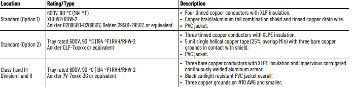
Shielded/Armored Cable
Shielded cable contains all general benefits of multi-conductor cable with the added benefit of a copper braided shield that can contain
much of the noise that is generated by a typical AC drive. Strong consideration for shielded cable should be given in installations with
sensitive equipment such as weigh scales, capacitive proximity switches and other devices that may be affected by electrical noise in the
distribution system. Applications with large numbers of drives in a similar location, imposed EMC regulations or a high degree of
communications/ networking are also good candidates for shielded cable.
Shielded cable may also help reduce shaft voltage and induced bearing currents for some applications. In addition, the increased impedance
of shielded cable may help extend the distance that the motor can be located from the drive without the addition of motor protective devices
such as terminator networks.
Consideration should be given to all general specifications that are dictated by the environment of the installation, including temperature,
flexibility, moisture characteristics and chemical resistance. In addition, a braided shield should be included and be specified by the cable
manufacturer as having coverage of at least 75%. An additional foil shield can greatly improve noise containment.
A good example of recommended cable is Belden 295xx (xx determines gauge). This cable has four (4) XLPE insulated conductors with a
100% coverage foil and an 85% coverage copper braided shield (with drain wire) surrounded by a PVC jacket.
Other types of shielded cable are available, but the selection of these types may limit the allowable cable length. Particularly, some of the
newer cables twist four conductors of THHN wire and wrap them tightly with a foil shield. This construction can greatly increase the cable
charging current required and reduce the overall drive performance. Unless specified in the individual distance tables as tested with the
drive, these cables are not recommended and their performance against the lead length limits supplied is not known.
Maximum Motor Cable Lengths
For information on maximum motor cable lengths, see the Wiring and Grounding Guidelines for Pulse Width Modulated (PWM) AC Drives,
publication DRIVES-IN001.
Power Wiring
The PowerFlex 700 has the following built in protective features to help simplify installation:
• Ground fault protection during startup and running ensures reliable operation
• Electronic motor overload protection increases motor life
• Removable MOV to ground and common mode capacitors to ground ensure compatibility with ungrounded systems. These devices
must be disconnected if the drive is installed on a resistive grounded distribution system, an ungrounded distribution system, a B
phase grounded distribution system or impedance grounded system. These devices must also be disconnected if the drive power
source is a regenerative unit (such as a bus supply and brake) or is DC fed from an active converter.
• 6 kV transient protection provides increased robustness for 380…480V system voltages
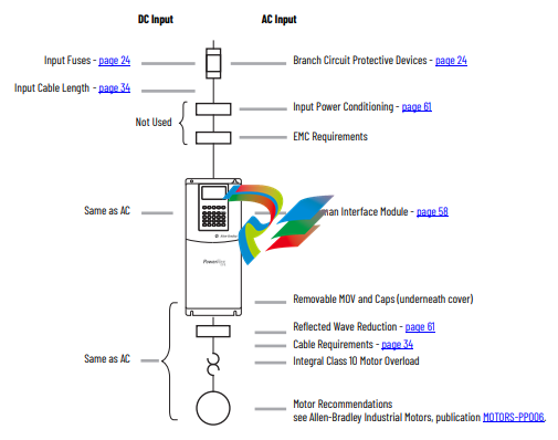
There are many other factors that must be considered for optimal performance in any given application. The block diagram below highlights
the primary installation considerations. Consult the Wiring and Grounding Guidelines for Pulse Width Modulated (PWM) AC Drives, publication
DRIVES-IN001 for detailed recommendations on input power conditioning, dynamic braking, reflected wave protection and motor cable
types.
-
 AMAT 0100-00046 AC Current Sense PWB
 -
 AMAT A0414720 Precision Advanced System Controller
 -
 AMAT 0010-00017 Precision Semiconductor Process Interface
 -
 AMAT 01-82889-00 High-Performance Semiconductor Component
 -
 ABB Sample Gas Cooler SCC-C 23070-0-10232110
 -
 IBA ibaRackline-PCHD Efficient process analysis with ibaHD-Server
 -
IBA ibaRackline-PC CAM Frame-accurate video information with ibaCapture
-
IBA ibaRackline-PC Highly available and reliable
-
 IBA Optical Signal Multiplier ibaBM-FOX-i-3o-D
 -
 IBA Optical Data Distribution System ibaBM-DIS-i-8o
 -
IBA Optical Data Concentrator ibaBM-COL-8i-o
-
 IBA ibaNet750-BM-D Acquisition via FO
 -
 IBA ibaW-750 Acquisition via Ethernet
 -
 IBA ibaPADU-8AI-I Compact Measurement Modules
 -
 IBA ibaPADU-D-8AI-I Compact Measurement Modules
 -
 IBA ibaPADU-8AI-U Compact Measurement Modules
 -
 IBA ibaPADU-D-8AI-U Compact Measurement Modules
 -
 IBA ibaPADU-4-AI-U Compact Measurement Modules
 -
 IBA ibaPADU-C-8AI Self-Supplied Data Logger
 -
 IBA ibaBM-ENetIP Bus monitor for EtherNet/IP
 -
 IBA ibaBM-eCAT Bus monitor for EtherCAT
 -
 IBA ibaBM-DP Bus monitor for PROFIBUS
 -
 IBA ibaBM-PN: Bus monitor for PROFINET IO
 -
 IBA ibaMS3xAI-1A Precision AC Current Measurement Module
 -
 IBA ibaDAQ Intelligent Central Unit
 -
 IBA ibaPQU-S Power Quality Monitoring System
 -
 IBA ibaCMU-S Condition Monitoring Unit (CMU)
 -
 IBA ibaPADU-S-IT-2x16 Modular data acquisition and control system
 -
IBA ibaPADU-S-CM Modular data acquisition system
-
 IBA ibaM-4AI-IEPE Input module
 -
IBA ibaM-4AI-UI Input module
-
IBA ibaM-4AI-150V-AC Input module
-
 IBA ibaM-4AI-600V-AC Input module
 -
 IBA ibaLink-SM-256V: High-Density PLC Data Interface
 -
 IBA ibaLink-SM-64V High-Performance S5/S7 Interface
 -
IBA ibaLink-SM-128V-i-2o Synchronous Fiber Optic (ibaNet)
-
 IBA ibaLink-SM-128V communication module
 -
IBA ibaM-4AI-5A-150A-AC Input module
-
 IBA ibaM-FO-2IO Interface module
 -
 IBA ibaM-COM Communication module
 -
 IBA ibaM-DAQ Intelligent Processor Module
 -
 B&R ECE161-0 MULTI digital input module
 -
 B&R ECCP70-01 MULTI CPU type B 42 KByte SRAM
 -
 B&R ECCP60-01 MULTI CPU type B 42 KByte SRAM
 -
 B&R DI426 digital input module
 -
 B&R 2DS100.60-1 electronic drum sequencer Absolut encoder
 -
 B&R 2CP100.60-1 CPU MODULE
 -
 B&R 2BM100.9 High-performance I/O module
 -
 AMAT 0190-14928 SCR Power Controller (PVD Reverse Zone)
 -
 AMAT 0500-01065 300mm Loadlock Interface Interlock Board
 -
 AMAT 2000-21123 Advanced Vacuum Seal Assembly
 -
 AMAT 0660-00090 High-Performance Industrial Power Filter
 -
 AMAT 0240-34077 Centura Endpoint Controller Kit
 -
 AMAT 0195-10215 High-Precision Pedestal Assembly
 -
 AMAT 0190-76050 VGA Video Controller VME Module
 -
 AMAT 0190-75084 High-Performance Communication & Logic Controller
 -
 AMAT 0190-60287 Precision VME/cPCI Interface Control Module
 -
 AMAT 0190-53752 DI Water I/O Controller PCB
 -
 AMAT 0190-37993 DeviceNet Scanner Pro (3U CompactPCI)
 -
 AMAT 0190-37833 MKS CDN500R-5 EPI 300mm Interface Module
 -
AMAT 0190-37771 MKS CDN500R Interlock Control Module
-
 AMAT 0190-37616 High-Precision Analog Input/Output Interface
 -
 AMAT 0190-36787B ISAC CP I/O Block 2 (Top) - Revision B
 -
 AMAT 0190-36787 ISAC CP I/O Block 2 (Top)
 -
AMAT 0190-36511 DIP294 DeviceNet I/O Control Block
-
 AMAT 0190-35764 & 0190-35765: Precision Control Interface Duo
 -
 AMAT 0190-35763 High-Performance Integrated Power Module
 -
 Applied Materials (AMAT) 0190-34512 4-Channel DeviceNet Scanner Interface
 -
 Applied Materials (AMAT) 0190-34282 High-Stability Process Control Module
 -
Applied Materials (AMAT) 0190-27707 High-Precision DeviceNet I/O Controller
-
 Applied Materials (AMAT) 0190-27072 High-Performance Semiconductor Interface
 -
 AMAT 0190-24007 CPCI-3720CF Single Board Computer
 -
 AMAT 0190-23905 Spellman ESC High Voltage Power Supply
 -
 AMAT 0190-22967 High-Density Analog I/O Control Board
 -
 AMAT 0190-22543 High-Precision Analog Input/Output Module
 -
 AMAT 0190-17964 Etch DPS Interlock Module
 -
 AMAT 0190-17894 Interlock Module Conductor HART
 -
 AMAT 0190-17081 2U CompactPCI System Host Processor
 -
 AMAT 0190-16926 and 0190-16928 Based on Compact PCI
 -
AMAT 0190-15915 Intelligent I/O Control Module
-
 AMAT 0190-15840 4-Port UPA DeviceNet Interface Module
 -
 AMAT 0190-15384 Advanced Digital Signal Interface Module
 -
 AMAT 0190-14027 Wafer Flat Finder PCB
 -
 AMAT 0190-12695 SBS CL7 3U CompactPCI Single Board Computer
 -
 AMAT 0190-11817 CP3-SER16-TTL 16-Port Serial Interface Card
 -
 AMAT 0190-11524 CDN500-25 Interlock Module
 -
 AMAT 0190-07450 CompactPCI 48-Channel Digital I/O Interface Board
 -
 AMAT 0190-05990-001 Maglev Rotation System Controller (300mm)
 -
 AMAT 0190-05647 LK3710 Serial Module Transition Card
 -
 AMAT 0190-04457 High-Performance Integrated Circuit Control Module
 -
 Applied Materials (AMAT) 0190-04098 | 5.X Factory Interface I/O Distribution Board
 -
 Applied Materials (AMAT) 0190-03705 | MF Producer SE/E Interlock Module
 -
 Applied Materials (AMAT) 0190-02748 | Flex Scanner Transition Module
 -
 Applied Materials (AMAT) 0190-02362 | Mainframe Interlock 1 Relay Module
 -
 Applied Materials (AMAT) 0190-01227 | Intelligent Motor Control OMS Board
 -
 Applied Materials (AMAT) 0190-00318 | VME 486 Video Controller
 -
 Applied Materials (AMAT) 0130-14007 | Advanced RF Signal Assembly
 -
 Applied Materials (AMAT) 0130-14005 | RF Cable/Interface Assembly
 -
 Applied Materials (AMAT) 0130-01218 | High-Efficiency RF Interface Controller
 -
 Applied Materials (AMAT) 0110-77040 | Head Pneumatic Controller
 -
 Applied Materials (AMAT) 0110-00077 | Precision Control Module
 -
 AMAT 0101-57015 high-performance Next-Generation Deflection Amplifier Board
 -
 AMAT 0100-77040 critical Head Pneumatic Controller Board
 -
 AMAT 0100-76291 Data Buffer / Memory Expansion Interface
 -
 AMAT 0100-76290 Advanced I/O Interface Board
 -
 AMAT 0100-76269 Control Board / Interface Module
 -
 AMAT 0100-71462-01 high-performance Process Controller PCB
 -
 AMAT 0100-71171 Chamber Interlock Control PCB
 -
 AMAT 0100-71154 Semiconductor Circuit Board / Electronic Group Card
 -
 AMAT 0100-70034 PCB Assembly (PCBA) for Endpoint VGA I/O Interconnect.
 -
 AMAT 0100-38032 ESC (Electrostatic Chuck) Controller PCB
 -
 AMAT 0100-36035 DPS Source Match / Seriplex I/O Distribution PCB
 -
 AMAT 0100-35231 Seriplex I/O Distribution Module
 -
 AMAT 0100-35217 TC Amp Interlock PCB Module
 -
 AMAT 0100-35065 High-Precision Serial Isolator PCB
 -
 AMAT 0100-35054 Advanced Chamber Interface Module
 -
 AMAT 0100-20453 DeviceNet Digital I/O Interface Board
 -
 AMAT 0100-20100 High-Performance Semiconductor Component
 -
 AMAT 0100-20068 Precision CCD Image Control Board
 -
 AMAT 0100-20064 Advanced Semiconductor Control Module
 -
Applied Materials (AMAT) 0100-20018 Advanced Communication Interface Module
-
 Applied Materials (AMAT) 0100-20016 High-Performance Interface and Control Module
 -
 Applied Materials (AMAT) 0100-20003 Digital I/O (DI/DO) Interface Board
 -
 Applied Materials (AMAT) 0100-20001 System Electronics Interface (SEI) / PCB Assembly
 -
 Applied Materials (AMAT) 0100-11030 Chamber Hardware / Gas Distribution Component
 -
 Applied Materials (AMAT) 0100-11022 Semiconductor Board Card
 -
 Applied Materials (AMAT) 0100-11018 Advanced Interface Control Module
 -
 Applied Materials (AMAT) 0100-11001 Precision Analog Output Board


