
schneiderModicon Quantum automation platform
How can you fit a 6000-page catalog in your pocket ?
Schneider Electric provides you with the complete set of industrial automation catalogs all on a handy
USB key for PC or in an application for tablets
Digi-Cat, a handy USB key for PC

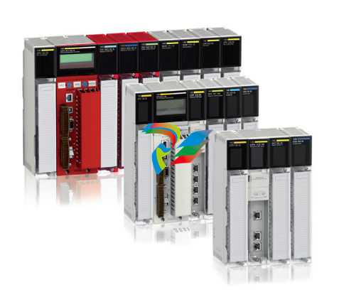
Modicon Quantum automation
platform
To the world of Schneider Electric
Presentation
This catalogue presents the range of Modicon Quantum PLCs and includes new
products, such as CPUs, power supplies and communication modules, which extend
the field of application of the range in the various standard and safety industrial
application areas.
With an already wide selection of I/O modules, and an already extensive offer in
terms of communication on fieldbuses and networks, Modicon Quantum is even
better suited to the needs of continuous or semi-continuous industrial processes and
control of large infrastructure sites.
Capitalizing as it does on more than 25 years' experience in redundant processing
architectures, and fully meeting safety requirements for people, production
installations and their environment, Modicon Quantum is the ideal solution for
applications requiring maximum availability in complete safety

Applications
The Modicon Quantum offer is, de facto, inherently designed for high availability
applications in the areas below:
b Petrochemicals
b Metallurgy
b Cement
b Energy
b Tunnels
b Airports
b Water treatment
b Mines
b Hydropower

Modicon Quantum automation
platform
Unity Pro standard CPUs
Presentation
The CPUs for the Modicon Quantum automation platform are based on highperformance processors and are compatible with Unity Pro software. Numerous
functions are included as standard in Quantum CPUs:
b Superior scan times and fast I/O acquisition
b Ability to handle interrupts (timed and I/O based)
b Handling of Fast task, as well as a Master task
b Memory expansion using PCMCIA cards
b Multiple communication ports integrated in the CPU
b Ease of diagnostics and maintenance via the LCD display block on the front panel
of high-end CPUs
The CPUs offered have different memory capacities, processing speeds and
communication options.
Protected backed up memory
As standard, the CPUs store the application program in a battery-backed internal
RAM. This battery is located on the front of the CPU and can be replaced while the
CPU is running.
A switch enables the application to be made secure against malicious tampering via
a remote connection.
To protect the application program from inadvertent changes during operation, the
CPUs feature a key switch on the front panel to protect the memory. This key switch
can also be used to start and stop the CPU. The 140CPU31110 CPU only has a
memory-protect slide switch.
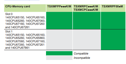
The high-end 140CPU65150, 140CPU65160, 140CPU65260, 140CPU67060,
140CPU67160, 140CPU67260 and 140CPU67261 CPUs have 2 slots for a
PCMCIA card:
b An upper slot (no. 0) for a memory expansion card (programs, symbols, constants
and/or data storage)
b A lower slot (no. 1) for a data storage memory expansion card
Besides the large-capacity internal RAM, the high-end 140CPU65860 and
140CPU67861 CPUs have 1 slot for a PCMCIA card:
b One slot for a data storage memory expansion card
Built-in communication ports
Quantum CPUs incorporate, depending on the model:
b Two RS 232 Modbus ports (1 RS 232/485 Modbus port for 140CPU6pppp CPUs)
b One Modbus Plus port
b One TCP/IP 10BASE-T/100BASE-TX Ethernet TCP/IP port (100BASE-FX for
140CPU67p6p Hot Standby CPUs)
b One USB port for connecting a programming PC terminal for the CPUs
LCD display
Depending on the model, the CPUs have an LCD display (2 lines of 16 characters)
with adjustable brightness and contrast controls. The keypad associated with the
display can be used for diagnostics, access to certain configuration parameters and
starting and stopping the CPU.
Modicon Quantum automation
platform
Unity Pro standard CPUs
Presentation (continued)
Hot Standby redundancy
140CPU67060, 140CPU67160, 140CPU67260, 140CPU67261 and 140CPU67861
CPUs are dedicated to the availability function of Hot Standby applications. They
have a 100 Mbps Ethernet fibre optic link and the Hot Standby function can be
diagnosed using the LCD display.
The 140CPU67261 and 140CPU67861 CPUs are specifically designed for Hot
Standby applications for which the distance between the two Hot Standby CPUs can be
as much as 16 km.
Some CPUs have increased capability in terms of memory, number of drops, and
online functions, etc. See the dedicated description pages for more information.
Quantum application design and installation
Use of these Quantum CPUs requires:
b Unity Pro Large or Extra Large programming software. This software is
compatible with the Premium, M580 and M340 platforms.
b Optionally, as required:
v Unity EFB toolkit software for developing EF and EFB function block libraries in
C language
v Unity Dif software for comparing Unity Pro applications
v Unity Loader software for updating Unity Pro projects
Cybersecurity
Schneider Electric has always taken care of the security of its systems. Security
guidelines are available for our customers to ensure their systems are protected
from attacks.
Modicon Quantum is a cyber-secure platform thanks to its advanced built-in
cybersecurity features and robustness.
The Modicon Quantum automation platform also offers the following features:
b Protection against unauthorized remote connections via an online editable Access
Control List
b Protection against remote programming changes via a password
b Option to enable or disable HTTP or FTP services
b Integrity of Unity Pro executable files
b Unnecessary services disabled by default
b Security features enabled by default
Modicon Quantum automation
platform
Unity Pro standard CPUs
Description
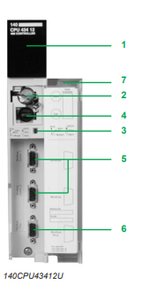
Standard CPUs
140CPU31110 and 140CPU43412U CPU front panels comprise:
1 A display block with 7 LEDs:
v Ready LED (green): Power-up diagnostic tests successful
v Run LED (green): Program executing
v Modbus LED (green): Activity on the Modbus port
v Modbus Plus LED (green): Activity on the Modbus Plus port
v Mem Prt LED (orange): Memory write-protected (memory protection switch
activated)
v Bat Low LED (red): Backup battery needs replacing or is missing
v Error A LED (red): Communication fault on the Modbus Plus port
2 A backup battery slot (1)
3 A slide switch for selecting the Modbus port communication parameters
v A slide switch (140CPU31110 model) for write-protecting the memory
4 A key switch (140CPU43412U models):
v Stop position: The PLC is stopped and program modifications are not
permitted
v Mem Prt position: The PLC is either stopped or running and program
modifications are not permitted
v Start position: The PLC is either stopped or running, program modifications
are permitted
5 Two 9-way female SUB-D connectors for connecting to the Modbus bus
6 A 9-way female SUB-D connector for connecting to the Modbus Plus network
7 A removable hinged door with a customizable identification label
Modicon Quantum automation
platform
Unity Pro standard CPUs
Description (continued)
High performance CPUs
140CPU65150, 140CPU65160, 140CPU65260, 140CPU65860, 140CPU67060,
140CPU67160, 140CPU67260, 140CPU67261 and 140CPU67861 CPU front
panels comprise:
1 An LCD display cover, providing access to:
2 A key switch:
v Unlocked: All system operations can be invoked and all changeable module
parameters can be modified via the LCD and keypad. The memory is not
write-protected
v Locked: No system operations can be invoked and all changeable module
parameters are read-only. Memory is write-protected and the application program
safeguarded. This mode avoids malicious tampering via a remote connection
3 A backup battery slot (1)
4 A reset button (Restart)
5 An LCD display (2 lines of 16 characters) with brightness and contrast controls
6 A 5-button keypad with 2 LEDs (ESC, ENTER, MOD, Z, C)
7 An RJ45 connector for connecting to the Modbus bus
8 A type B female USB connector for connecting the programming PC terminal
9 A 9-way female SUB-D connector for connecting to the Modbus Plus network
10Two slots for PCMCIA memory expansion cards:
10.a The upper slot (no.0) for a memory expansion card (except for models
140CPU65860 and 140CPU67861)
10.b The lower slot (no.1) for data storage memory expansion card (all models)
11 Two LEDs:
v COM LED (green): Activity on the Ethernet port (140CPU65150,
140CPU65160, 140CPU65260 and 140CPU65860 models), activity on the Hot
Standby primary or secondary drop (140CPU67060, 140CPU67160,
140CPU67260, 140CPU67261 and 140CPU67861 models)
v ERR LED (red): Ethernet frame collision (140CPU65150, 140CPU65160,
140CPU65260 and 140CPU65860 models), communication error between the
Hot Standby primary and secondary drops (140CPU67060, 140CPU67160,
140CPU67260, 140CPU67261 and 140CPU67861 models)
12A connector:
v RJ45 connector for connection to the Ethernet network (140CPU65150,
140CPU65160, 140CPU65260 and 140CPU65860 models)
v MT-RJ multimode fibre optic connector (140CPU67060, 140CPU67160 and
140CPU67260 models) or LC single mode fibre optic connector (140CPU67261
and 140CPU67861 model) for interconnecting the primary and standby PLCs in
the Hot Standby architecture
Modicon Quantum automation
platform
Unity Pro standard CPUs
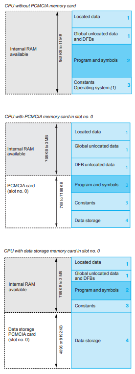
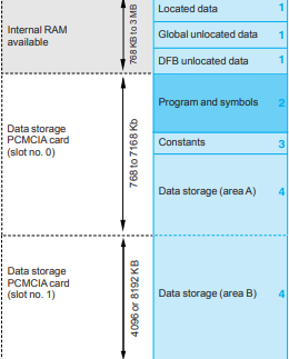
Memory structure
The application memory is divided into memory areas physically distributed in the
internal RAM and on 1 or 2 PCMCIA memory expansion cards (2 PCMCIA cards on
models 140CPU65150, 140CPU65160, 140CPU65260, 140CPU67060,
140CPU67160, 140CPU67260, 140CPU67261 and 140CPU67861, and 1 on
models 140CPU65860 and 140CPU67861):
1 Application data area always in internal RAM. This area is broken down into
2 types of data, to be used according to the user's habits and preferences:
v Global located data, corresponding to data defined by an address (for example,
%MW237) with which a symbol can be associated (for example,
Counting_rejects).
v Unlocated data, corresponding to data defined only by a symbol. This type of
addressing removes the memory “mapping” management constraints because
the addresses are assigned automatically.
v DFB unlocated data corresponding to DFB user function blocks. The size of this
object area is only limited by the size of the internal RAM physical memory
available.
2 Application program and symbols area in the internal RAM or in the PCMCIA
memory card (descriptor, executable code for the tasks and application symbols
database)
3 Constants area in internal RAM or the PCMCIA memory card (constant words,
initial values and configuration)
4 Area for storing additional data that can be used for distributed applications to
store information such as production data and manufacturing recipes (only on
140CPU65150, 140CPU65160, 140CPU65260, 140CPU65860, 140CPU67060,
140CPU67160, 140CPU67260, 140CPU67261 and 140CPU67861 CPUs)
According to the application memory size requirements, two memory structures are
possible depending on whether the Quantum CPU has 0, 1 or 2 PCMCIA memory
expansion cards:
b Application in internal RAM, the application is completely loaded into the CPU’s
battery-backed internal RAM (2) the capacity of which depends on the CPU model.
b Application in the PCMCIA card, the internal RAM is reserved for the application
data. The PCMCIA memory card contains the program space (program, symbols
and constants areas). Certain types of PCMCIA memory card also take the data
storage area.
The presence of the symbols area with the program area is optional. The fact of
having the application symbols database on the PLC means that, when it is
connected to an empty programming PC (with no applications), all the elements
needed to debug or upgrade this PLC are available
Memory structure (continued)
Modicon Quantum automation
platform
Unity Pro standard CPUs
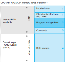
CPU with 2 PCMCIA memory cards in slot no. 0 and no. 1
Memory structure (continued)
Expansion of the file storage area
With the TSXMRPF004M, TSXMRPF008M file storage memory cards (4096 or
8192 KB):
b A file storage area can be provided when the application is completely loaded in
the internal RAM
b Memory space can be freed up for the program when the application is in the
PCMCIA card
The Unity Pro programming software assists the application designer with
management of the structure and the occupation of memory space in the
Quantum PLC.
Protecting the application
Whether located in the internal RAM or in the PCMCIA card, the application can be
protected with a key switch (see page 1/8 and page 1/9), in order to prohibit access
to it
(read or modify program) online in Unity Pro.
Modicon Quantum automation
platform
PCMCIA memory expansion cards
Unity Pro
Presentation
PCMCIA memory expansion cards make it possible to expand the RAM memory
capacity of high-performance Quantum CPUs.
Depending on the model, these cards are designed to accommodate:
b The application program, symbols and constants
b The additional application data
b Or both
PCMCIA memory expansion cards
These cards provide three different storage types:
b Storage of the application: Program, symbols, and constants in a common space
of 512 KB to 4096 KB: TSXMFPPpppK/M for Flash EPROM memories
b Storage of the application and additional data, comprising:
v An application area of 192 KB to 7 MB
v A data storage area of up to 7 MB for additional data
The limit between these two spaces is configurable. The configurable cards are:
v TSXMRPCpppK/M for SRAM memories
v TSX MCPCpppK/M for Flash EPROM and SRAM memories
b Storage of additional data, provided by SRAM TSXMRPF004M, TSXMRPF008M
4 or 8 MB memory cards
These cards use two technologies:
b Battery-backed SRAM
Used particularly in the application program design and debugging phases.
These cards provide:
v All of the application's transfer and modification services in online mode
v Additional data storage
The memory is protected by a removable battery built into the PCMCIA card.
A second auxiliary battery is present to enable the main battery to be replaced
without loss of data.
b Flash EPROM
Used when debugging of the application program is complete. This is used to:
v Overcome battery life restrictions
v Perform one global application transfer
When in use, it is impossible to carry out modifications to the application in online
mode.
Program modification in online mode
Only those expansion cards in which the program is stored in SRAM memory
TSXMRPCpppK/M allow program modifications to be carried out in online mode.
A user with a CPU equipped with a memory expansion card and who wishes to make
modifications or additions to the program in online mode must structure the
application program in several reasonably sized sections.
Modicon Quantum automation
platform
Racks
Description
Five different rack models are available, with 3, 4, 6, 10 or 16 slots. The rack slots
are universal (any module can fit into any slot). Almost all Quantum modules are
designed to fit into a single slot in a Quantum rack (1).
There are no reserved slots in a Quantum system, although it is recommended that
power supply modules are fitted in the extreme left slot, for optimum heat dissipation.
The only limits on the rack are the power available for the modules and the
addressing space. Any rack can be used in any of the three architectures supported
by the Quantum platform: Local I/O, remote I/O or distributed I/O.
In a Quantum system, module addressing and configuration is handled by the
software. No switches or other hardware components are used.
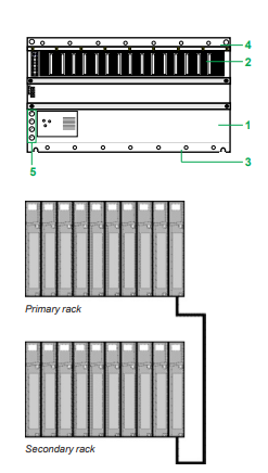
140XBP0pp00 racks comprise:
1 A metal frame
2 Connectors for module/rack connection
3 Tapped holes for fixing each module
4 Holes for fixing the rack
5 Earth terminals for earthing the rack
Rack expansion module
The 140XBE10000 rack expansion module enables I/O in an adjacent “secondary”
rack to communicate with the CPU or RIO drop in the “primary” rack via a specific
communication cable. An expansion module must be installed in each rack. The
extension cable provides all the signals necessary for data transmission between the
two racks. A single rack expansion module can be added to each rack.
The rack expansion module has the following flexible characteristics:
b The same 140XBE10000 rack expansion module is used for both “primary” and
“secondary” racks. A rack expansion system consists of two 140XBE10000 rack
expansion modules and one cable, available in 1, 2 or 3 m lengths.
b The system can use any Quantum power supply module. Each rack can have a
different type of power supply module.
b Loss of power in the “secondary” rack will not shut down the entire drop.
Only those modules located in the “secondary” rack will lose power.
b Rack expansion modules can be placed in any slot in the rack and do not
necessarily have to be placed in corresponding slots in the “primary” and
“secondary” racks.
b The rack expansion module is not recognized by the configuration software.
It will appear as an unfilled slot in the I/O map.
b All rack sizes are possible.
b The rack expansion module supports local I/O and remote I/O (31 drops).
b Expansion racks can take all discrete and analog I/O modules and also
high-speed counter modules.
-
 HIRSCHMANN MSM20-M2M2M2M2SY9HH9E Ethernet media modul
 -
 HIRSCHMANN SPIDER-PL-20-05T1999999TWVHHHH Industrial Ethernet Rail Switch
 -
 Hirschmann SPIDER-PL-20-07T1M2M299TWVHHHH Industrial ETHERNET Rail Switch
 -
.png) Hirschmann (Belden) RS20-1600M2M2SDAEHC09.1.00 DIN-rail managed industrial Fast Ethernet switch
Hirschmann (Belden) RS20-1600M2M2SDAEHC09.1.00 DIN-rail managed industrial Fast Ethernet switch -
 Hirschmann (Belden) RS30-1602O6O6TDAPHC09.1.00 DIN-rail managed industrial Ethernet switch
 -
 Hirschmann (Belden) RS30-2402O6T1SDAPHH09.0.13 DIN-rail industrial Ethernet switch
 -
Hirschmann (Belden) SPIDER-PL-20-04T1S29999TY9HHHH Ethernet DIN-rail switch
-
 HIRSCHMANN RS20-1600T1T1SDAUHX Switch
 -
 HIRSCHMANN BRS42-0012OOOO-SPCZ99HHSES industrial switch
 -
 Hirschmann RS20-0800S2S2TDHPHH09.0.14 Fast Ethernet DIN rail switch.
 -
 HIRSCHMANN MM20-Z6Z6M2M2SAHH Hybrid Fast Ethernet Media Module
 -
 HIRSCHMANN MM20-Z6Z6T1T1SAHH hot-swappable hybrid Fast Ethernet Media Module
 -
 HIRSCHMANN MM20-P9P9T1T1SAHH Hybrid Fast Ethernet Media Module
 -
 HIRSCHMANN MM20-M4T1T1T1SAHH Hybrid Fast Ethernet Media Module
 -
 HIRSCHMANN MM20-M4M4T1T1SAHH Hybrid Fast Ethernet Media Module
 -
 HIRSCHMANN MM20-M2M2M2M2SZHH Ethernet media module
 -
HIRSCHMANN MM20-M2M2M2M2SAHH Ethernet media module
-
 HIRSCHMANN MM20-T1T1T1T1EBH 4-port Fast Ethernet Copper Cable Media Module
 -
HIRSCHMANN MM20-T1T1T1T1SAHH 4-port Fast Ethernet Copper Cable Media Module
-
HIRSCHMANN MM20-T1T1T1T1SAHH 4-port Fast Ethernet Copper Cable Media Module
-
 HIRSCHMANN MM20-Z6Z6EBH Hot-swappable fast Ethernet media module
 -
 HIRSCHMANN MM20-Z6Z6SAHH Ethernet media module
 -
HIRSCHMANN MM20-Z6Z6Z6Z6EBH Industrial Media Module
-
 MSM40-T1T1T1TZ9HH9E99.9.99 HIRSCHMANN Switch
 -
 HIRSCHMANN MS20-0800SAAEHC / MS20-0800SAAEHC0 8-port modular Layer 2 management Ethernet switch
 -
 Hirschmann RSPM20-4T14T1SZ9HHS9 Switch RSPM20-4T14T1SZ9HHS9
 -
 HIRSCHMANN RS20-1600M2M2SDAEHH09.1. RS20/30/40 Managed Switch configurator
 -
HIRSCHMANN RS20-1600M2M2SDAEHX09.0.00 Ethernet switch
-
 HIRSCHMANN BELDEN SPIDER-PL-20-07T1M2M299TY9HHHH / SPIDERPL2007T1M2M299TY9HHHH
 -
HIRSCHMANN MM3-1FXS2/3TX1 Switching Board Module
-
 HIRSCHMANN RSPE30-24044O7T99-ECCP999HHSE2A08.1.00 Industrial-grade fanless management-type Ethernet switch
 -
 HIRSCHMANN RS30-1602OOZZSDAEHC09.1.00 DIN-rail-mounted managed Layer 2 Ethernet switch
 -
 HIRSCHMANN MACH104-20TX-F Managed 24-port Full Gigabit 19" Switch
 -
 HIRSCHMANN Switch RS20-0800M4M4SDAE
 -
Hirschmann RS30-1602O6O6SDAEHH09.1. Management-type Ethernet switch
-
 Hirschmann RS30-1602OOZZSDAEHC09.0.10 Open rack-style Ethernet switch
 -
 HIRSCHMANN RSPE30-24044O7T99-SCCV999HHSI2SXX.X.XX High-Availability Seamless Redundancy
 -
HIRSCHMANN RSPE30-24044O7T99-SCCZ999HHSE2A DIN-rail Ethernet switch
-
HIRSCHMANN MM2-4TX1-EEC switch
-
HIRSCHMANN MSM40-T1T1T1T1TZ9HH9E99.9.99 Module
-
 HIRSCHMANN RS20 Rail Switch RS20-0400S4T1SDAEHC07.1.01
 -
 HIRSCHMANN M4-FAST8-SFP Fast Ethernet media module
 -
 HIRSCHMANN RS20-0400M2T1SDAP Managed Fast-Ethernet-Switch
 -
 HIRSCHMANN BELDEN SPIDER II 8TX/1FX EEC Industrial Ethernet Rail Switch
 -
HIRSCHMANN MM3-2FXS2/2TX1
-
 HIRSCHMANN RS2-4TX/1FX EEC Industrial Ethernet Rail Switch
 -
 RS30-0802O6O6SDAEHC09.0.10 HIRSCHMANN Switch
 -
 HIRSCHMANN m4-8TP-RJ45 Ethernet Media Module
 -
 HIRSCHMANN MSP30-24040SCZ9URHHE3A switch
 -
 Hirschmann rack MS30-1602SAAPHC
 -
 HIRSCHMANN RS2-FX/FX Industrial Switch Module
 -
Rs1txfx - Hirschmann - Rs1-Tx/Fx Rail Switch
-
RS20-0800S2S2SDAEHC09.1.00 HIRSCHMANN Commutator
-
 Hirschmann EAGLE20 TX/TX Industrial Security Router
 -
 Hirschmann SPIDER-SL-20-04T1S29999SY9HHHH Industrial Switch
 -
 HIRSCHMANN MAR1040-4C4C4C4C9999SMMHRHHXX.X. Gigabit Ethernet Switch configurator
 -
 Hirschmann MAR1040 Industrial Switch
 -
 HIRSCHMANN BELDEN RS30-1602O6O6SDAE
 -
Hirschmann RS20-1600M2M2SDAUHC Ethernet DIN rail switch
-
 HIRSCHMANN OCTOPUS 24M industrial switch
 -
 HIRSCHMANN RS20-1600T1T1SDAE Management-type Ethernet switch
 -
 HIRSCHMANN RS20-1600T1T1SDAUHH industrial switch
 -
HIRSCHMANN RS20-0800M2M2SDAPHC09.0.04 switch
-
 Hirschmann MR 8-03 24V DC Industrial Modular Bridge/Router
 -
 HIRSCHMANN RS20-0400M2T1SDAPHC08.0.01 Managed Switch
 -
 MACH1130 Hirschmann Industrial Switch
 -
 HIRSCHMANN 943824-002 SPIDER 5TX Industrial Ethernet Switch
 -
 HIRSCHMANN RS30-0802O6O6SDAEHC09.1.00 Managed Industrial Switch
 -
 HIRSCHMANN RS20-0400M2M2TDAEHC04.0.01 Industrial Switch
 -
 HIRSCHMANN BRS20-0600Z6Z6-STCZ99HHSES Industrial Switch
 -
 HIRSCHMANN MACH104-20TX-FR-L3P Industrial Ethernet Switch
 -
 HIRSCHMANN RS40-0009CCCCEDBPHH06.0.01 Industrial Switch
 -
 HIRSCHMANN RS2-3TX/2FX EEC Industrial Ethernet Switch
 -
 Hirschmann MACH 1020/1030 Fast/Gigabit Rack Mount Switches
 -
HIRSCHMANN RS20-0800M2M2SDAPHC09.0.14 Industrial Switch
-
 HIRSCHMANN RS20-1600T1T1SDAEHC09.0.04 Industrial Switch
 -
 HIRSCHMANN RSB20-0800T1T1EAABHH Industrial Switch
 -
 HIRSCHMANN MACH4002-48+4G-L3E Industrial Backbone Switch
 -
 HIRSCHMANN RS20-0400S2T1SDAE Industrial Managed Switch
 -
HIRSCHMANN RS20-0800S2T1SDAUHC Industrial Switch
-
 HIRSCHMANN RS20-2400S4S4SDAEHC09.0.14 industrial switch
 -
 HIRSCHMANN OS20-001200T5T5T5- TBBZ999HHNE3S 08.1.00 industrial switch
 -
HIRSCHMANN OS20-001200T5T5T5- TBBZ999HHNE3S 08.1.00 industrial switch
-
 HIRSCHMANN RS40-0009CCCCSDAEHH09.0.14 switch
 -
 Hirschmann RS20-1600T1T1SDAUHC Management-type Ethernet Switch
 -
 Hirschmann M1-8SFP Switche
 -
Hirschmann Industrial Ethernet Ruggedized Switch MACH1000 Family
-
 Basler Electric, Solid State Protective Relay, BE1-60
 -
BASLER ELECTRIC SR4A-2B15B3A Static Voltage Regulator
-
.png) BASLER ELECTRIC EXCITER DIODE MONITOR EDM-200
BASLER ELECTRIC EXCITER DIODE MONITOR EDM-200 -
.png) BASLER ELECTRIC DECS125-15-B2C5 DIGITAL EXCITATION CONTROL SYSTEM V 2.0.9
BASLER ELECTRIC DECS125-15-B2C5 DIGITAL EXCITATION CONTROL SYSTEM V 2.0.9 -
 BASLER ELECTRIC BE1-851 OVERCURRENT PROTECTION RELAY MECHANISM
 -
 Basler Electric BE1-51A / BE151A
 -
 Basler Electric BE1-40Q Loss of Excitation Relay
 -
 Basler Electric BE1-87G Variable Percentage Differential Relay
 -
 Basler Electric BE1-11 Protection System I5A3M2P2N0EA00
 -
 BASLER ELECTRIC DECS-200-1C Digital Excitation Control System
 -
 Basler Electric / Kohler BE1-11g Generator Protection Relay G5A3M2J2N0E000
 -
BASLER ELECTRIC DECS125-15 DIGITAL EXCITATION CONTROL SYSTEM
-
 BASLER ELECTRIC BE1-951 OverCurrent Protecton System
 -
Basler Electric DECS-200-1L Digital Excitation Control System
-
 Basler Electric DGC-2020HD-5NS1DNSBA Digital Genset Controller -
 -
 BASLER ELECTRIC BE1-81T1EE1WA0N1F / BE181T1EE1WA0N1F
 -
 BASLER ELECTRIC BE1-25M1EA6PN5R1F / BE125M1EA6PN5R1F
 -
 BASLER ELECTRIC DECS-250-LN1SN1N DIGITAL EXCITATION CONTROL SYSTEM
 -
Basler Electric DECS-250-CN2CN 1N Digital Excitation Control System Unit
-
 BASLER ELECTRIC DECS-300-C0N0 DIGITAL EXCITATION CONTROL SYSTEM
 -
 BASLER ELECTRIC BE1-87T-A1E-A1J-D0S1F / BE187TA1EA1JD0S1F
 -
BASLER ELECTRIC BE1-11-G6D1M0J2P0E000 Protection System
-
 BASLER ELECTRIC BE1-GPS100-E4N1H1N GENERATOR PROTECTION SYSTEM
 -
 Jaquet Relay card (Auxiliary module) FTV 3090 377Z-03985
 -
 Jaquet Trip Chain Control card FTBU 3034 377Z-05030
 -
 Jaquet with input card -E04 FTFU 3024 -E04 377Z-05855
 -
 Jaquet with input card -E03 FTFU 3024- E03 377Z-03983
 -
 Jaquet FTFU 3024- E02 377Z-03982 with input card -E02
 -
 Jaquet FTFU 3024-E01 377Z-03981 with input card -E01
 -
 Hirschmann RS20-2400T1T1SDAE Industrial Managed Ethernet Switch
 -
 Hirschmann BELDEN EAGLE30-04022O6TT999SCCV9HSE3F
 -
 Hirschmann MM3-2FXS2/2TX MICE Media Module
 -
 Hirschmann RS20-1600M2M2SDAPHC08.0.05 Industrial Managed Switch
 -
 Hirschmann OZD Profi 12M G12-1300 PRO Fieldbus Repeater
 -
Hirschmann SPIDER 4TX/1FX-ST EEC Industrial Ethernet Switch
-
 Hirschmann MM2-2FXM3/2TX1 MICE Media Module
 -
 Hirschmann RS20-2400M2M2SDAPHC09.0.14 Industrial Switch
 -
 Hirschmann RS20-0400M2M2SDAEHC07.1.05 OpenRail Switch
 -
 Hirschmann OZD Profi 12M G12-EEC Fieldbus Repeater
 -
HIRSCHMANN MDA422-1/2-3.5c-23/46 sensor
-
Hirschmann RS30-2402T1T1SDAUHC Managed Industrial Switch


