ABBDCS880Hardware manual DCS880 Drives (20 A ... 5200 A)
WARNING – DCS880 sizes H4 ... H8: – The drive is heavy. Lift the drive by lifting lugs only. – The drive’s center of gravity is high. Do not tilt the unit. The unit will overturn from a tilt of about 6 degrees. An overturning drive can cause physical injury. – Do not lift the unit by the front cover. – Place units H4 … H6 only on their back. – Make sure that dust from drilling does not enter the drive when installing. Electrically conductive dust inside the unit may cause damage or lead to malfunction. – Ensure sufficient cooling. – Do not fasten the drive by riveting or welding
Operation
These warnings are intended for all who plan the operation of the drive or operate the drive. Ignoring the instructions can cause physical injury or death and/or damage to the equipment.
WARNING – Before adjusting the drive and putting it into service, make sure that the motor and all driven equipment are suitable for operation throughout the speed range provided by the drive. The drive can be adjusted to operate the motor at speeds above and below the base speed. – Do not control the motor with the disconnecting device (disconnecting mains); instead, use the control panel keys and , or commands via the I/O board of the drive. – Mains connection: You can use a disconnect switch (with fuses) to disconnect the electrical components of the drive from the mains for installation and maintenance work. The type of disconnect switch used must be as per EN 60947-3, Class B, so as to comply with EU regulations, or a circuit-breaker type which switches off the load circuit by means of an auxiliary contact causing the breaker's main contacts to open. The mains disconnect must be locked in its "OPEN" position during any installation and maintenance work. – EMERGENCY STOP buttons must be installed at each control desk and at all other control panels requiring an emergency stop function. Pressing the STOP button on the control panel of the drive will neither cause an emergency stop of the motor, nor will the drive be disconnected from any dangerous potential. – To avoid unintentional operating states, or to shut the unit down in case of any imminent danger according to the standards in the safety instructions it is not sufficient to merely shut down the drive via signals "RUN", "drive OFF" or "Emergency Stop" respectively "control panel" or "PC tool". – Intended use: The operating instructions cannot take into consideration every possible case of configuration, operation or maintenance. Thus, they mainly give such advice only, which is required by qualified personnel for normal operation of the machines and devices in industrial installations. If in special cases the electrical machines and devices are intended for use in non-industrial installations - which may require stricter safety regulations (e.g. protection against contact by children or similar) - these additional safety measures for the installation must be provided by the customer during assembly.
Note: – When the control location is not set to Local (Local not shown in the status row of the display), the stop key on the control panel will not stop the drive. To stop the drive using the control panel, press the Loc/Rem key and then the stop key
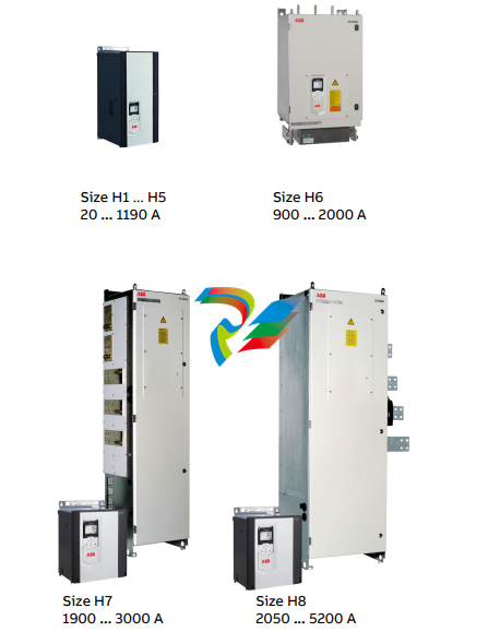
The DCS880 Chapter overview This chapter describes briefly the operating principle and construction of the converter modules in short. The DCS880 converter modules The DCS880-S size H1 ... H8 are intended for controlling DC motors.
Mechanical installation Chapter overview This chapter describes the mechanical installation of the DCS880. Safety
WARNING Examining the installation site The drive must be installed in an upright position with the cooling section against a wall. Make sure that the installation site agrees with these requirements: – The installation site has sufficient ventilation to prevent overheating of the drive. See chapter Current ratings. – The operation conditions of the drive agree with the specifications in chapter Environmental Conditions. – The wall is vertical, not flammable and strong enough to hold the weight of the drive. – The material below the installation is not flammable. – There is enough free space above, beside and belo
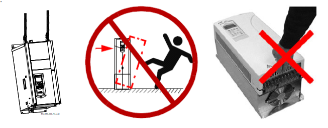
w the drive for cooling air flow, service and maintenance. There is enough free space in front of the drive for operation, service and maintenance. See chapter Dimensions and weights. Necessary tools – Drill and drill bits. – Screwdriver and/or wrench with bits. Some drive covers have torx screws. Moving the drive Move the transport package by pallet truck to the installation site. – DCS800 sizes H4 ... H8: – The drive is heavy. Lift the drive by lifting lugs only. – The drive’s center of gravity is high. Do not tilt the unit. The unit will overturn from a tilt of about 6 degrees. An overturning drive can cause physical injury. – Do not lift the unit by the front cover. Place units H4 … H6 only on their back
Delivery check Check that there are no signs of damage. Before attempting installation and operation, check the information on the nameplate of the converter module to verify that the unit is of the correct type. The label includes an IEC rating, cTÜVus, C-tick (N713) and CE markings, a type code and a serial number, which allow individual identification of each unit. The remaining digits complete the serial number so that there are no two units with the same serial number. See an example nameplate below.
