
GE350 Feeder Protection System
the following order:
A. Remove the 2 mounting screws near letters A and C, of label ABC (item#2), and
mount 2 standoffs.
B. Remove the 2 mounting screws near the letters B and E, of label ABCDE (item#3),
and mount 2 standoffs.
2. Place the IP20 cover (item#4) and secure it with 4 screws (item#5) using the suggested
tightening torque of 8lb-in.
NOTE
NOTE: Make sure the device terminals are wired before placing the cover. Use the 5 slots located
on each side of the cover to guide the wires outside of the cover.
Retrofit kit for IP20
Before attaching the cover, remove the old labels from the device (see item#2 and item#3)
and replace them with the new labels from the retrofit kit. Attach the cover as described in
the previous section.
Arc flash sensors
Arc flash sensors house the fiber optics that are used to detect the arc flash. Mounting
details depend on the sensor type (point or loop).
For detailed installation, testing and maintenance guidance for Arc Flash sensors, see GET20057 3 Series Arc Flash Application Note.
If the relay is used in the computation for reducing the Hazard Reduction Category
code, operands for sensor failures must be assigned to an auxiliary output relay which
must be connected into the control logic of the breaker equipment to ensure safe
operations when the output relay is asserted. In the event of this assertion, the Hazard
Reduction Category code cannot be maintained unless backup protection is continuing
to maintain it.
CAUTION: This product uses optical electronic devices (line or point sensors) to sense arc flash
fault conditions. It is recommended to follow proper housekeeping measures &
establish a regularly scheduled preventive maintenance routine to ensure proper
device operation. For maintenance recommendations, see GET-20057 3 Series Arc
Flash Application Note
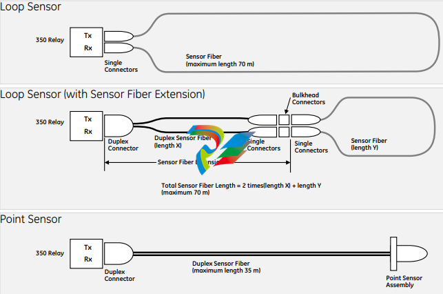
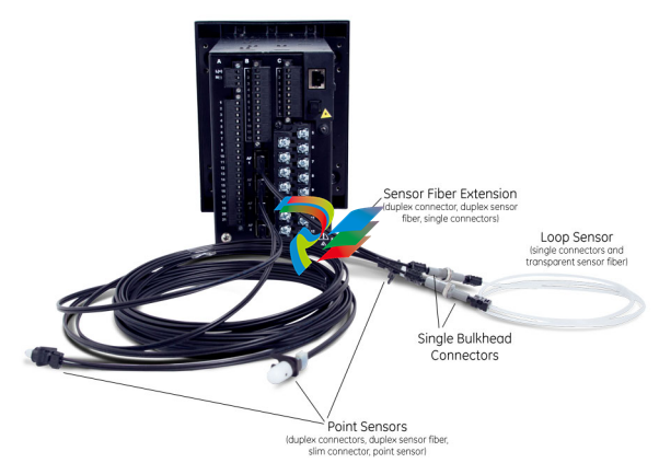
Arc flash sensors are available in two different configurations, point and loop. Loop sensors
can be used with a black-coated sensor fiber extension to connect the ends of the loop
sensor to the 350 relay through panels up to 51 mm (2 inches) thick.
Arc Flash sensor fiber is pressure sensitive and must be handled carefully to avoid
damage. Read the following guidelines fully before proceeding.
Care must be taken when handling the Arc Flash sensor fiber, which can be damaged if
twisted, bent, or clamped tightly during installation.
• Do not bend sensor fiber sharply, or with a radius of less than 35 mm (1.3 inches).
Sharp bends can damage the fiber. Do not pull or tug loops of sensor fiber, as sharp
bends may result.
• Do not clamp sensor fiber tightly during installation. Sensor fiber should be held in
place loosely for the best long-term performance. Avoid over-tightening ties which
may deform or break the sensor fiber.
• Do not pull or tug sensor fiber with force, as this may cause internal damage or
separate the fiber from the cable connector.
• Do not twist the sensor fiber, as twisting can damage the fiber resulting in
substandard performance.
• Do not attach sensor fiber directly to the bus or other live conductors.
• Avoid surface temperatures above 70 °C or 158 °F to prolong the life of the fiber.
• Secure all sensor fibers (loosely but securely) away from any moving parts.
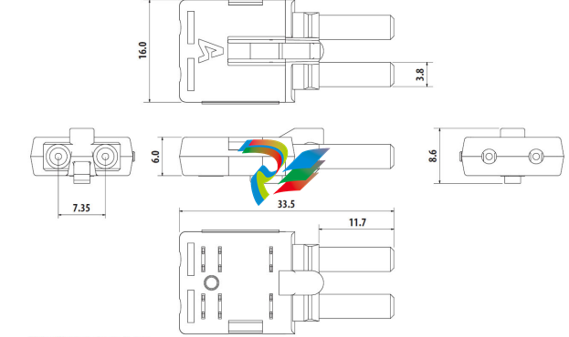
The point sensor fiber includes a duplex connector to connect to the back of the 350 relay
on one end, and a compressed slim connector that connects to the sensor itself on the
other end.
Before installing the AF sensor units, ensure that all other drilling and installation is
complete to minimize possible damage to the sensitive unit and connected sensor fiber
cable. Choose a location for the sensor clear of any obstructions that could shield the
sensor from arc flash light.
FASTPATH: Review the sensor fiber handling guidelines above.
Sensor fiber should be held in place loosely for the best long-term performance. Avoid
over-tightening ties which may deform or break the sensor fiber.
General installation:
1. Choose a location for the point sensor.
Arc flash point sensors should be installed clear of any obstructions that could shield
the sensor from arc flash light, and less than 2m (6ft 6") from any potential arc flash
source.
The sensor head should be pointed towards the most likely source of arc flash.
For further guidance selecting point sensor locations, see GET-20057 3 Series Arc
Flash Application Note.
2. Remove the slim connector from the point sensor assembly.
3. Carefully route the duplex sensor fiber from the point sensor location to the back of
the relay unit, minimizing loops and curves for the strongest possible signal. Ensure all
sensor fiber handling precautions are followed.
The slim connecter fits through holes with a diameter of 11 mm or greater, and can be
threaded through holes drilled in any panels between the relay and arc flash detection
location.
NOTE
NOTE: Install protective grommets when routing sensor fiber through metal walls.
4. Mount the point sensor using either a cable tie mount or through-hole mount, as
-
 Beckhoff PLC module CX1020-0000 Basic CPU module (service phase)
 -
 Beckhoff CP7812-1056-0010 15" Multitouch Display Control Panel
 -
 Beckhoff CX5120-0115 /2GB Controller Module
 -
 Beckhoff CP7201-1000-0000 Industrial Panel PC
 -
 Beckhoff Servo Motor AM8061-0JH1-0000
 -
 BECKHOFF CP6503-0001-0050 Built-in Panel PC
 -
 Beckhoff CP3919-0010 Display G190ETN01.2 19" PCT V04. Multi-touch Control Panel
 -
 Beckhoff CX5110-0112-9020/000368201 Embedded PC Intel Atom Processor
 -
 Beckhoff AX8206-0000 Dual-Axis Module
 -
Beckhoff Nail Operating Terminal CP7032-1031-0010
-
Beckhoff AM8042-0EH1-0000 Servomotor 4.10 Nm (M0), F4 (87 mm)
-
 Beckhoff EK9300 Beckhoff CPU Module
 -
Beckhoff CP3224-0020 Multitouch-Panel-PC
-
 Beckhoff CP2712-0000 12.1" 24VDC Touch Screen WMD0
 -
 BECKHOFF CX5240-0195 / 0000289234 Embedded PC 40 GB CFast Card
 -
 Beckhoff CP6932-1000-0000 Control Panel
 -
 BECKHOFF CX5120-0121 PLC Module
 -
 Beckhoff EL3218 | EtherCAT Terminal, 8-channel analog input
 -
 Beckhoff C6640-0050 | Control cabinet Industrial PC
 -
 Beckhoff Cx5130-0120/4GB Embedded-PC
 -
 BECKHOFF CX2030-0122 PLC PROCESSOR
 -
 BECKHOFF CX5020-0122 Controller Module
 -
 Beckhoff CP3915-0000 Multitouch Panel
 -
 BECKHOFF EL3014 | EtherCAT Terminal
 -
 BECKHOFF Industrial Computer c6920-1057-0030
 -
 Beckhoff CX5130-0141/4GB CX5130-0141 Embedded PC
 -
 Beckhoff C6240-1052-0040 4-086-06-3073 Industrial Computer
 -
 Beckhoff CX5140-0135 /4GB High-Performance Embedded Industrial PC
 -
 Beckhoff C6515-1001-0000 Industrial PC
 -
 Beckhoff AX5103-0000-0200 - Digital Compact Servo Drives
 -
 Beckhoff CX2030-0130-1003/4GB Basic CPU module
 -
 Beckhoff AX8620-0000 Power Supply Module
 -
 Beckhoff CX9020-0111 module with
 -
 Beckhoff EL7332 PLC Module
 -
 BECKHOFF CP7709-0001-0020 HMI
 -
 Beckhoff CX5120-0155/2GB Embedded PC
 -
 BECKHOFF CP7037-1037-0010 OPERATOR INTERFACE TOUCHSCREEN
 -
 Beckhoff EK9000 | ModbusTCP/UDP Bus Coupler
 -
 Beckhoff Touch Panel Screen CP6020 -0000-0000
 -
 Beckhoff CX2020-0121 Module FAST Shipping
 -
 Beckhoff CX2030-0125 Basic CPU Module
 -
 Beckhoff CP3918-0000 Multi-Touch 18.5" Control Panel
 -
 Automotion LC4A00010 DC BL Motor Control, ATS, Sub Assy, SCP, 115VAC,
 -
 500T-115VAC - VAS ENGINEERING - DORIC 500 SERIES DIGITAL TEMP INDICATOR
 -
 Honeywell X-DCS2000/EN Digital Integrated System Manager 50/60Hz 100-240V #4
 -
 Kollmorgen S60600 Servostar600 606-Fan 4 kVA, 6 A, 3 X 230 - 480 V
 -
 ABB XZ C828 A101 Didt Dioder Snubber 3BHE039453R0101
 -
 ABB 3BHB027232R0001 1-Phase Charging Transformer
 -
 ABB 3BHE006412R0101 Circuit Board UFC762AE101
 -
 ABB XVC770BE101 3BHE021083R0101 Circuit Board
 -
 ABB 3BHE021887R0101 (Model: UBCC717BE101 / UBC717BE101) is an advanced
 -
 ABB 3BHE032593R0001 Isolated Power Supply
 -
 ABB 3BSC610023R0001 POWER SUPPLY SD812
 -
 Beckhoff C6650-0060 | Control cabinet Industrial PC
 -
 Beckhoff CP2916-0000 Industrial HMI Display Panel
 -
 Beckhoff AM8053-0L2B-0000 Servomotor 15.4 Nm (M0), F5 (104 mm)
 -
 Beckhoff CP6202-0001-0020 Industrial Panel PC
 -
Beckhoff CX2020-0120 Plc Module
-
 Beckhoff CX1010-0111 BASIC CPU MODULE
 -
 Beckhoff C6017-0010 | Ultra-compact Industrial PC
 -
 BECKHOFF CX2040-0155 Plc Module
 -
 Beckhoff CX5120-0125 Embedded PC
 -
 BECKHOFF C6930-0040 INDUSTRIAL CONTROL COMPUTER
 -
 Beckhoff CP6907-0001-0000 Economy Built-in Control Panel
 -
 Beckhoff CP2912-0000 Multi-Touch Built-In Control Panel
 -
 Beckhoff C6015-0010 Ultra-Compact Industrial PC
 -
 Beckhoff CX5130 | Embedded PC with Intel Atom® E3827
 -
 Beckhoff C6030-0060 Ultra-Compact Industrial PC
 -
 OMRON 3G3XV-A2007 3G3XV-A2007-NEV2
 -
 Omron NJ1019000 NJ1 programable logic controller
 -
 OMRON C120-LK202-EV1/C120LK202EV1
 -
 OMRON C200H-AD003 PLC
 -
 OMRON C200H-CPU23-E COIL 24VDC PLC
 -
 Omron C200HG - C200H-ID212- C200H-OC226 C200HW-BC101 PLC Base Unit
 -
 OMRON C200H-OC222(Output Unit),C200H-PS211(Power Supply Unit),SP001 Module Rack
 -
 OMRON C200H-RT201 PROGRAMMABLE CONTROLLER
 -
 OMRON C200HS-CPU01-E SYSMAC PROGRAMMABLE CONTROLLER
 -
 OMRON C200H-SNT31 C200H Programmable Controllers
 -
 OMRON C200HW-MC402-E Motion control unit
 -
 OMRON C200PC-ISA02-DRM-E PLC ISA bus compatible board card
 -
 OMRON C500-CT012 PLC
 -
 OMRON C500-NC103-E PLC
 -
 OMRON C500-NC222-E PLC
 -
 OMRON C500-PRW05-V1 PLC
 -
 OMRON C500-PRW06 PROGRAMMABLE CONTROLLER
 -
 OMRON C500-PS223-E 3G2A5-PS223-E PLC SYSMAC PROGRAMMABLE CONTROLLER
 -
 OMRON C500-TU001 3G2A5-TU001 PLC PLC
 -
 OMRON C60H-C1DR-DE-V1 Programmable Controllers
 -
 OMRON C60H-C5DR-DE-V1 Programmable Controllers
 -
 OMRON C60H-C6DR-DE-V1 Programmable Controllers
 -
 OMRON CJ1G-CPU44H CPU module
 -
 OMRON CJ1G-CPU45H PLC
 -
 OMRON CJ1M-CPU13-ETN V4.0 PLC PLC
 -
 OMRON CJ1W-AD041-V1 Analog input uni
 -
 OMRON CJ1W-CORT21 PLC module
 -
 OMRON CJ1W-IDP01 Input unit
 -
 OMRON CJ1W-MCH71 - MECHATROLINK-II
 -
 OMRON CJ1W-MD261 Digital I/O
 -
 OMRON CJ1W-NC413 Position control unit
 -
 OMRON CJ1W-NCF71 Position Control Units
 -
 OMRON CJ1W-PTS51 Process Simulation I/O Module
 -
 OMRON CJ1W-PTS52 Process Simulation I/O Module
 -
 OMRON CJ1W-SCU21-V1 PLC
 -
 Omron CJ1W-SCU22 Serial Communication Unit
 -
 OMRON CJ1W-TC001 CJ Series Temperature Control Unit
 -
 Omron CK3W-AX1515N Motion Controller
 -
 Omron CP1E-N60DR-D Compact PLC CPU
 -
 OMRON CP1E-NA20DT1-D PLC PLC
 -
 OMRON CP1H-X40DT-D plc PLC
 -
 OMRON CPM2C-S110C-DRT Interface module
 -
 OMRON CQM1-AD041 PLC
 -
 SAACKE F‑GDSA‑1 / F‑GDSA‑2 Feuerungsautomaten
 -
 SAACKE F-GDSA 143303 Controller SHIPS UPS
 -
 ICS Triplex T8270 Trusted 24 Vdc FanAssembly
 -
 SCHNEIDER M522220000 SA SM_DO16R 16 DIGITAL OUTPUTS MODULE
 -
 LENZ EPL10200-W EPZ-10203 CANPT010W3E
 -
 OMRON CQM1H-ADB21 PLC
 -
OMRON CQM1H-CPU61 PLC
-
 OMRON CQM1H-MAB42 PLC
 -
 OMRON CQM1-TC102 CQM1-TC101 PLC
 -
 OMRON CS1G-CPU44-EV1 PLC
 -
 OMRON CS1G-CPU44H CPU
 -
OMRON CS1H-CPU63-EV1 PLC
-
 OMRON CS1H-CPU66-V1 PLC
 -
 OMRON CS1W-CLK13 PLC communication module
 -
OMRON CS1W-EIP21 PLC
-
 OMRON CS1W-MAD44 PLC PLC
 -
 OMRON CS1W-SCU31-V1 CVM1-BC103 PLC


