
GE350 Feeder Protection System
detailed below.
5. Reconnect the slim connector to the point sensor.
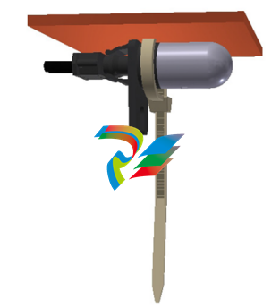
Arc flash point sensors can be installed in one of two ways, using a cable tie mount or a
through-hole mount.
Cable tie mount:
• Requires a 2.5-mm-wide cable tie.
• Mount the sensor on a stick or similar using the cable tie, as shown in the following
figure.
Through-hole mount
• Requires a standard or self-tapping M3 screw, and optionally an M3 washer.
• Mount the sensor through a 10 mm hole made in the surface of any mechanical
structure inside the switchgear or on the surface of one side of the switchgear itself,
as shown in the following figure.
Make sure there is no dirt or dust inside the point sensor or on the surface because it
reduces the capturing efficiency of the device, increases its transmission loss, or both. If
the point sensor is covered with dust, clean it by blowing or wiping the dust off the point
sensor.
FASTPATH: The material of the point sensor is not affected by water-based cleaning agents, dish
soap, or organic solvents with an alcohol (ethanol) base. Do not use solvents or solvent
mixtures that contain acids because they can attack or dissolve the optical plastic
material.
Before installing the AF sensor units, ensure that all other drilling and installation is
complete to minimize possible damage to the sensitive unit and connected sensor fiber
cable.
FASTPATH: Review the sensor fiber handling guidelines above.
Sensor fiber should be held in place loosely for the best long-term performance. Avoid
over-tightening ties which may deform or break the sensor fiber.
FASTPATH: The loop sensor fiber can be connected directly to the 350 relay without a sensor fiber
extension, however, care must be taken to ensure correct alignment of the loop sensor
single connectors into the 350 light sensor input.
Installing the loop sensor fiber without an extension:
1. Plan the path of the loop sensor fiber, looping through the chamber or chambers
requiring arc flash detection. See GET-20057 3 Series Arc Flash Application Note for
detailed examples of loop sensor installation.
2. Ensure that both ends of the loop remain close together and can reach the 350 relay
light sensor inputs.
3. Install the loop sensor carefully, following all sensor fiber handling guidelines.
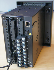
4. Plug the single connectors into the back of the 350 relay, ensuring correct alignment
as shown
Installing the loop sensor fiber with a sensor fiber extension:
1. Plan the path of the loop sensor fiber, looping through the chamber or chambers
requiring arc flash detection. See GET-20057 3 Series Arc Flash Application Note for
detailed examples of loop sensor installation.
2. Ensure that both ends of the loop remain close enough together to be reached by the
sensor fiber extension. If needed, gently pull apart the duplex sensor fiber extension
from the end with two single connectors, being careful not to bend the fiber with a
radius of less than 35 mm (1.3 inches).
3. Ensure that the sensor fiber extension is long enough to reach the 350 relay from the
bulkhead connector location.
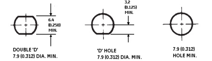
4. Mount the bulkhead connector on the side of the chamber, following the drill hole
dimensions provided. Note that the single bulkhead connector uses washers 11.0 mm
(0.420 in) wide, so the drill holes must be spaced accordingly if the loop sensor path
begins and ends in the same place.
Figure 2-26: Bulkhead connector cutout
5. Install the loop sensor carefully, following all sensor fiber handling guidelines.
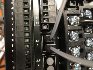
6. Plug the ends of the loop sensor into the bulkhead connectors.
7. Plug the single connectors on the sensor fiber extension into the other sides of the
bulkhead connectors, and the duplex connector into the back of the 350 relay
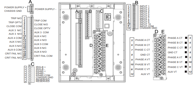
Wire range
Use the following guidelines when selecting wires or lugs to connect to terminal blocks
A,B,C,D,E (Drawout case design), and terminal blocks D,E (Non-drawout case design):
• 12 AWG to 22 AWG (3.3 mm2 to 0.3 mm2): Single wire termination with/without
9.53 mm (0.375”) maximum diameter ring terminals (#8).
• 14 AWG to 22 AWG (2.1 mm2 to 0.3 mm2): Multiple wire termination with matching
wire sizes and stranding. Two wires maximum per circuit.
• 14 AWG to 22 AWG (2.1 mm2 to 0.3 mm2): Multiple wire termination with 9.53 mm
(0.375”) maximum diameter ring terminals (#8). Two ring terminals maximum per
circuit.
• Suggested wiring screw tightening torque, tighten to 12 in-lb (1.35 N-m).
• Minimum suggested temperature rating for the conductors is 75C.
Use the following guidelines when selecting wires to connect to terminal strip F (Drawout
case design), and terminal strips A,B,C (Non-drawout case design):
• 12 AWG to 24 AWG (3.3 mm2 to 0.2 mm2)
• Suggested wiring screw tightening torque: 4.5 in-lbs (0.5 N-m)
• The uncovered communications cable shield connected to the common terminal
should not exceed 1” (2.5 cm) for proper EMC shielding of the communications cable.
Phase sequence and transformer polarity
For correct operation of the relay features, the user must follow the instrument
-
 Beckhoff PLC module CX1020-0000 Basic CPU module (service phase)
 -
 Beckhoff CP7812-1056-0010 15" Multitouch Display Control Panel
 -
 Beckhoff CX5120-0115 /2GB Controller Module
 -
 Beckhoff CP7201-1000-0000 Industrial Panel PC
 -
 Beckhoff Servo Motor AM8061-0JH1-0000
 -
 BECKHOFF CP6503-0001-0050 Built-in Panel PC
 -
 Beckhoff CP3919-0010 Display G190ETN01.2 19" PCT V04. Multi-touch Control Panel
 -
 Beckhoff CX5110-0112-9020/000368201 Embedded PC Intel Atom Processor
 -
 Beckhoff AX8206-0000 Dual-Axis Module
 -
Beckhoff Nail Operating Terminal CP7032-1031-0010
-
Beckhoff AM8042-0EH1-0000 Servomotor 4.10 Nm (M0), F4 (87 mm)
-
 Beckhoff EK9300 Beckhoff CPU Module
 -
Beckhoff CP3224-0020 Multitouch-Panel-PC
-
 Beckhoff CP2712-0000 12.1" 24VDC Touch Screen WMD0
 -
 BECKHOFF CX5240-0195 / 0000289234 Embedded PC 40 GB CFast Card
 -
 Beckhoff CP6932-1000-0000 Control Panel
 -
 BECKHOFF CX5120-0121 PLC Module
 -
 Beckhoff EL3218 | EtherCAT Terminal, 8-channel analog input
 -
 Beckhoff C6640-0050 | Control cabinet Industrial PC
 -
 Beckhoff Cx5130-0120/4GB Embedded-PC
 -
 BECKHOFF CX2030-0122 PLC PROCESSOR
 -
 BECKHOFF CX5020-0122 Controller Module
 -
 Beckhoff CP3915-0000 Multitouch Panel
 -
 BECKHOFF EL3014 | EtherCAT Terminal
 -
 BECKHOFF Industrial Computer c6920-1057-0030
 -
 Beckhoff CX5130-0141/4GB CX5130-0141 Embedded PC
 -
 Beckhoff C6240-1052-0040 4-086-06-3073 Industrial Computer
 -
 Beckhoff CX5140-0135 /4GB High-Performance Embedded Industrial PC
 -
 Beckhoff C6515-1001-0000 Industrial PC
 -
 Beckhoff AX5103-0000-0200 - Digital Compact Servo Drives
 -
 Beckhoff CX2030-0130-1003/4GB Basic CPU module
 -
 Beckhoff AX8620-0000 Power Supply Module
 -
 Beckhoff CX9020-0111 module with
 -
 Beckhoff EL7332 PLC Module
 -
 BECKHOFF CP7709-0001-0020 HMI
 -
 Beckhoff CX5120-0155/2GB Embedded PC
 -
 BECKHOFF CP7037-1037-0010 OPERATOR INTERFACE TOUCHSCREEN
 -
 Beckhoff EK9000 | ModbusTCP/UDP Bus Coupler
 -
 Beckhoff Touch Panel Screen CP6020 -0000-0000
 -
 Beckhoff CX2020-0121 Module FAST Shipping
 -
 Beckhoff CX2030-0125 Basic CPU Module
 -
 Beckhoff CP3918-0000 Multi-Touch 18.5" Control Panel
 -
 Automotion LC4A00010 DC BL Motor Control, ATS, Sub Assy, SCP, 115VAC,
 -
 500T-115VAC - VAS ENGINEERING - DORIC 500 SERIES DIGITAL TEMP INDICATOR
 -
 Honeywell X-DCS2000/EN Digital Integrated System Manager 50/60Hz 100-240V #4
 -
 Kollmorgen S60600 Servostar600 606-Fan 4 kVA, 6 A, 3 X 230 - 480 V
 -
 ABB XZ C828 A101 Didt Dioder Snubber 3BHE039453R0101
 -
 ABB 3BHB027232R0001 1-Phase Charging Transformer
 -
 ABB 3BHE006412R0101 Circuit Board UFC762AE101
 -
 ABB XVC770BE101 3BHE021083R0101 Circuit Board
 -
 ABB 3BHE021887R0101 (Model: UBCC717BE101 / UBC717BE101) is an advanced
 -
 ABB 3BHE032593R0001 Isolated Power Supply
 -
 ABB 3BSC610023R0001 POWER SUPPLY SD812
 -
 Beckhoff C6650-0060 | Control cabinet Industrial PC
 -
 Beckhoff CP2916-0000 Industrial HMI Display Panel
 -
 Beckhoff AM8053-0L2B-0000 Servomotor 15.4 Nm (M0), F5 (104 mm)
 -
 Beckhoff CP6202-0001-0020 Industrial Panel PC
 -
Beckhoff CX2020-0120 Plc Module
-
 Beckhoff CX1010-0111 BASIC CPU MODULE
 -
 Beckhoff C6017-0010 | Ultra-compact Industrial PC
 -
 BECKHOFF CX2040-0155 Plc Module
 -
 Beckhoff CX5120-0125 Embedded PC
 -
 BECKHOFF C6930-0040 INDUSTRIAL CONTROL COMPUTER
 -
 Beckhoff CP6907-0001-0000 Economy Built-in Control Panel
 -
 Beckhoff CP2912-0000 Multi-Touch Built-In Control Panel
 -
 Beckhoff C6015-0010 Ultra-Compact Industrial PC
 -
 Beckhoff CX5130 | Embedded PC with Intel Atom® E3827
 -
 Beckhoff C6030-0060 Ultra-Compact Industrial PC
 -
 OMRON 3G3XV-A2007 3G3XV-A2007-NEV2
 -
 Omron NJ1019000 NJ1 programable logic controller
 -
 OMRON C120-LK202-EV1/C120LK202EV1
 -
 OMRON C200H-AD003 PLC
 -
 OMRON C200H-CPU23-E COIL 24VDC PLC
 -
 Omron C200HG - C200H-ID212- C200H-OC226 C200HW-BC101 PLC Base Unit
 -
 OMRON C200H-OC222(Output Unit),C200H-PS211(Power Supply Unit),SP001 Module Rack
 -
 OMRON C200H-RT201 PROGRAMMABLE CONTROLLER
 -
 OMRON C200HS-CPU01-E SYSMAC PROGRAMMABLE CONTROLLER
 -
 OMRON C200H-SNT31 C200H Programmable Controllers
 -
 OMRON C200HW-MC402-E Motion control unit
 -
 OMRON C200PC-ISA02-DRM-E PLC ISA bus compatible board card
 -
 OMRON C500-CT012 PLC
 -
 OMRON C500-NC103-E PLC
 -
 OMRON C500-NC222-E PLC
 -
 OMRON C500-PRW05-V1 PLC
 -
 OMRON C500-PRW06 PROGRAMMABLE CONTROLLER
 -
 OMRON C500-PS223-E 3G2A5-PS223-E PLC SYSMAC PROGRAMMABLE CONTROLLER
 -
 OMRON C500-TU001 3G2A5-TU001 PLC PLC
 -
 OMRON C60H-C1DR-DE-V1 Programmable Controllers
 -
 OMRON C60H-C5DR-DE-V1 Programmable Controllers
 -
 OMRON C60H-C6DR-DE-V1 Programmable Controllers
 -
 OMRON CJ1G-CPU44H CPU module
 -
 OMRON CJ1G-CPU45H PLC
 -
 OMRON CJ1M-CPU13-ETN V4.0 PLC PLC
 -
 OMRON CJ1W-AD041-V1 Analog input uni
 -
 OMRON CJ1W-CORT21 PLC module
 -
 OMRON CJ1W-IDP01 Input unit
 -
 OMRON CJ1W-MCH71 - MECHATROLINK-II
 -
 OMRON CJ1W-MD261 Digital I/O
 -
 OMRON CJ1W-NC413 Position control unit
 -
 OMRON CJ1W-NCF71 Position Control Units
 -
 OMRON CJ1W-PTS51 Process Simulation I/O Module
 -
 OMRON CJ1W-PTS52 Process Simulation I/O Module
 -
 OMRON CJ1W-SCU21-V1 PLC
 -
 Omron CJ1W-SCU22 Serial Communication Unit
 -
 OMRON CJ1W-TC001 CJ Series Temperature Control Unit
 -
 Omron CK3W-AX1515N Motion Controller
 -
 Omron CP1E-N60DR-D Compact PLC CPU
 -
 OMRON CP1E-NA20DT1-D PLC PLC
 -
 OMRON CP1H-X40DT-D plc PLC
 -
 OMRON CPM2C-S110C-DRT Interface module
 -
 OMRON CQM1-AD041 PLC
 -
 SAACKE F‑GDSA‑1 / F‑GDSA‑2 Feuerungsautomaten
 -
 SAACKE F-GDSA 143303 Controller SHIPS UPS
 -
 ICS Triplex T8270 Trusted 24 Vdc FanAssembly
 -
 SCHNEIDER M522220000 SA SM_DO16R 16 DIGITAL OUTPUTS MODULE
 -
 LENZ EPL10200-W EPZ-10203 CANPT010W3E
 -
 OMRON CQM1H-ADB21 PLC
 -
OMRON CQM1H-CPU61 PLC
-
 OMRON CQM1H-MAB42 PLC
 -
 OMRON CQM1-TC102 CQM1-TC101 PLC
 -
 OMRON CS1G-CPU44-EV1 PLC
 -
 OMRON CS1G-CPU44H CPU
 -
OMRON CS1H-CPU63-EV1 PLC
-
 OMRON CS1H-CPU66-V1 PLC
 -
 OMRON CS1W-CLK13 PLC communication module
 -
OMRON CS1W-EIP21 PLC
-
 OMRON CS1W-MAD44 PLC PLC
 -
 OMRON CS1W-SCU31-V1 CVM1-BC103 PLC


