
GE350 Feeder Protection System
transformer polarities, shown in the Typical Wiring Diagram. Note the solid square
markings shown with all instrument transformer connections. When the connections
adhere to this drawing, the arrow shows the direction of power flow for positive watts and
the positive direction of lagging vars.The phase sequence is user programmable for either
ABC or ACB rotation.
Current inputs
The 350 relay has four (4) channels for AC current inputs, each with an isolating
transformer. There are no internal ground connections on the current inputs. Current
transformers with 1 to 6000 A primaries may be used.
CAUTION: Verify that the relay’s nominal input current of 1 A or 5 A matches the secondary rating
of the connected CTs. Unmatched CTs may result in equipment damage or inadequate
protection.
CAUTION: IMPORTANT: The phase and ground current inputs will correctly measure up to 20
times the current input’s nominal rating. Time overcurrent curves become horizontal
lines for currents above the 20 × CT rating. This becomes apparent if the pickup level is
set above the nominal CT rating.
CAUTION: Before working on CTs, they MUST be short circuited.
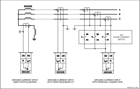
Ground and sensitive ground CT inputs
One dedicated ground input is referred to throughout this manual as the Ground Current
or Sensitive Ground Current input. Before making ground connections, consider that the
relay automatically calculates the neutral (residual) current from the sum of the three
phase current phasors. The following figures show three possible ground connections (or
three possible sensitive ground connections).
The ground input (Terminals D8 and E8) is used in conjunction with a Zero Sequence CT as
source, or in the neutral of wye-connected source CTs. The ground current input can be
used to polarize the neutral directional element. When using the residual connection set
the GROUND CT PRIMARY setpoint to a value equal to the PHASE CT PRIMARY setpoint.
In cases where the relay is equipped with sensitive ground CT (terminals D8 and E8) the
sensitive ground current input is intended for use either with a CT in a source neutral of a
high-impedance grounded system, or on ungrounded systems. On ungrounded systems it
is connected residually with the phase current inputs. In this case, the SENSTV GND CT
PRIMARY setpoint should be programmed to a value equal to the PHASE CT PRIMARY
setpoint. The sensitive ground current input can be connected to a Zero Sequence CT for
increased sensitivity and accuracy when physically possible in the system.
NOTE
NOTE: The Sensitive Ground input must only be used on systems where the maximum ground
current does not exceed current input specifications
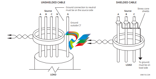
Zero sequence CT installation
The various CT connections and the exact placement of a Zero Sequence CT, for ground
fault current detection, are shown in the figure below. Twisted pair cabling on the Zero
Sequence CT is recommended.
Figure 2-35: Zero sequence core balance (CT) installation
Voltage inputs
The 350 relay has four channels for AC voltage inputs, each with an isolating transformer.
Voltage transformers up to a maximum 5000:1 ratio may be used. The nominal secondary
voltage must be in the 50 to 240 V range.The three phase inputs are designated as the “bus
voltage”. The Bus VT connections most commonly used, wye and delta (or open delta), are
shown in the typical wiring diagram.
NOTE
NOTE: If Delta VTs are used, the zero sequence voltage (V0) and neutral/sensitive ground
polarizing voltage (–V0) will be zero. Also, with the Delta VT connection, the phase-neutral
voltage cannot be measured and will not be displayed.
NOTE
NOTE: The 350 relay can be applied to both metering and protection feeders with up to 550 kV
phase-to-phase voltage. Please ensure that the selected VT ratio and VT secondary do not
result in a primary voltage exceeding 550 kV.
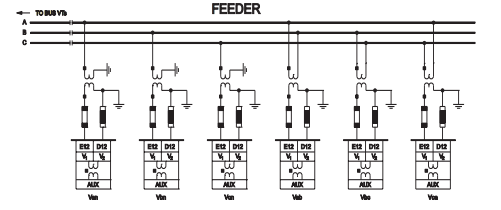
The single phase input is designated as the “Aux VT Input”. The Aux VT input channel can be
connected for either phase-neutral voltage Van, Vbn, Vcn, or for phase-phase voltage Vab,
Vbc, Vca as shown below.
Control power
CAUTION: Control power supplied to the relay must match the installed power supply range. If the
applied voltage does not match, damage to the unit may occur. All grounds MUST be
connected for safe, normal operation regardless of control power supply type.
The label found on the relay specifies its order code or model number. The installed power
supply’s operating range will be one of the following:
LO: 24 to 48 V DC (Range: 20 to 60 V DC)
HI: 125 to 250 V DC/120 to 240 V AC (Range: 84 to 250 V DC/60 to 300 V AC (50 and 60
Hz))
CAUTION: The relay should be connected directly to the ground bus, using the shortest practical
path. A tinned copper, braided, shielding and bonding cable should be used. As a
minimum, 96 strands of number 34 AWG should be used. Belden catalog number 8660
is suitable.
CAUTION: Isolate power prior to servicing.
An external switch, circuit breaker, or other protective device must be connected near to
-
 Beckhoff PLC module CX1020-0000 Basic CPU module (service phase)
 -
 Beckhoff CP7812-1056-0010 15" Multitouch Display Control Panel
 -
 Beckhoff CX5120-0115 /2GB Controller Module
 -
 Beckhoff CP7201-1000-0000 Industrial Panel PC
 -
 Beckhoff Servo Motor AM8061-0JH1-0000
 -
 BECKHOFF CP6503-0001-0050 Built-in Panel PC
 -
 Beckhoff CP3919-0010 Display G190ETN01.2 19" PCT V04. Multi-touch Control Panel
 -
 Beckhoff CX5110-0112-9020/000368201 Embedded PC Intel Atom Processor
 -
 Beckhoff AX8206-0000 Dual-Axis Module
 -
Beckhoff Nail Operating Terminal CP7032-1031-0010
-
Beckhoff AM8042-0EH1-0000 Servomotor 4.10 Nm (M0), F4 (87 mm)
-
 Beckhoff EK9300 Beckhoff CPU Module
 -
Beckhoff CP3224-0020 Multitouch-Panel-PC
-
 Beckhoff CP2712-0000 12.1" 24VDC Touch Screen WMD0
 -
 BECKHOFF CX5240-0195 / 0000289234 Embedded PC 40 GB CFast Card
 -
 Beckhoff CP6932-1000-0000 Control Panel
 -
 BECKHOFF CX5120-0121 PLC Module
 -
 Beckhoff EL3218 | EtherCAT Terminal, 8-channel analog input
 -
 Beckhoff C6640-0050 | Control cabinet Industrial PC
 -
 Beckhoff Cx5130-0120/4GB Embedded-PC
 -
 BECKHOFF CX2030-0122 PLC PROCESSOR
 -
 BECKHOFF CX5020-0122 Controller Module
 -
 Beckhoff CP3915-0000 Multitouch Panel
 -
 BECKHOFF EL3014 | EtherCAT Terminal
 -
 BECKHOFF Industrial Computer c6920-1057-0030
 -
 Beckhoff CX5130-0141/4GB CX5130-0141 Embedded PC
 -
 Beckhoff C6240-1052-0040 4-086-06-3073 Industrial Computer
 -
 Beckhoff CX5140-0135 /4GB High-Performance Embedded Industrial PC
 -
 Beckhoff C6515-1001-0000 Industrial PC
 -
 Beckhoff AX5103-0000-0200 - Digital Compact Servo Drives
 -
 Beckhoff CX2030-0130-1003/4GB Basic CPU module
 -
 Beckhoff AX8620-0000 Power Supply Module
 -
 Beckhoff CX9020-0111 module with
 -
 Beckhoff EL7332 PLC Module
 -
 BECKHOFF CP7709-0001-0020 HMI
 -
 Beckhoff CX5120-0155/2GB Embedded PC
 -
 BECKHOFF CP7037-1037-0010 OPERATOR INTERFACE TOUCHSCREEN
 -
 Beckhoff EK9000 | ModbusTCP/UDP Bus Coupler
 -
 Beckhoff Touch Panel Screen CP6020 -0000-0000
 -
 Beckhoff CX2020-0121 Module FAST Shipping
 -
 Beckhoff CX2030-0125 Basic CPU Module
 -
 Beckhoff CP3918-0000 Multi-Touch 18.5" Control Panel
 -
 Automotion LC4A00010 DC BL Motor Control, ATS, Sub Assy, SCP, 115VAC,
 -
 500T-115VAC - VAS ENGINEERING - DORIC 500 SERIES DIGITAL TEMP INDICATOR
 -
 Honeywell X-DCS2000/EN Digital Integrated System Manager 50/60Hz 100-240V #4
 -
 Kollmorgen S60600 Servostar600 606-Fan 4 kVA, 6 A, 3 X 230 - 480 V
 -
 ABB XZ C828 A101 Didt Dioder Snubber 3BHE039453R0101
 -
 ABB 3BHB027232R0001 1-Phase Charging Transformer
 -
 ABB 3BHE006412R0101 Circuit Board UFC762AE101
 -
 ABB XVC770BE101 3BHE021083R0101 Circuit Board
 -
 ABB 3BHE021887R0101 (Model: UBCC717BE101 / UBC717BE101) is an advanced
 -
 ABB 3BHE032593R0001 Isolated Power Supply
 -
 ABB 3BSC610023R0001 POWER SUPPLY SD812
 -
 Beckhoff C6650-0060 | Control cabinet Industrial PC
 -
 Beckhoff CP2916-0000 Industrial HMI Display Panel
 -
 Beckhoff AM8053-0L2B-0000 Servomotor 15.4 Nm (M0), F5 (104 mm)
 -
 Beckhoff CP6202-0001-0020 Industrial Panel PC
 -
Beckhoff CX2020-0120 Plc Module
-
 Beckhoff CX1010-0111 BASIC CPU MODULE
 -
 Beckhoff C6017-0010 | Ultra-compact Industrial PC
 -
 BECKHOFF CX2040-0155 Plc Module
 -
 Beckhoff CX5120-0125 Embedded PC
 -
 BECKHOFF C6930-0040 INDUSTRIAL CONTROL COMPUTER
 -
 Beckhoff CP6907-0001-0000 Economy Built-in Control Panel
 -
 Beckhoff CP2912-0000 Multi-Touch Built-In Control Panel
 -
 Beckhoff C6015-0010 Ultra-Compact Industrial PC
 -
 Beckhoff CX5130 | Embedded PC with Intel Atom® E3827
 -
 Beckhoff C6030-0060 Ultra-Compact Industrial PC
 -
 OMRON 3G3XV-A2007 3G3XV-A2007-NEV2
 -
 Omron NJ1019000 NJ1 programable logic controller
 -
 OMRON C120-LK202-EV1/C120LK202EV1
 -
 OMRON C200H-AD003 PLC
 -
 OMRON C200H-CPU23-E COIL 24VDC PLC
 -
 Omron C200HG - C200H-ID212- C200H-OC226 C200HW-BC101 PLC Base Unit
 -
 OMRON C200H-OC222(Output Unit),C200H-PS211(Power Supply Unit),SP001 Module Rack
 -
 OMRON C200H-RT201 PROGRAMMABLE CONTROLLER
 -
 OMRON C200HS-CPU01-E SYSMAC PROGRAMMABLE CONTROLLER
 -
 OMRON C200H-SNT31 C200H Programmable Controllers
 -
 OMRON C200HW-MC402-E Motion control unit
 -
 OMRON C200PC-ISA02-DRM-E PLC ISA bus compatible board card
 -
 OMRON C500-CT012 PLC
 -
 OMRON C500-NC103-E PLC
 -
 OMRON C500-NC222-E PLC
 -
 OMRON C500-PRW05-V1 PLC
 -
 OMRON C500-PRW06 PROGRAMMABLE CONTROLLER
 -
 OMRON C500-PS223-E 3G2A5-PS223-E PLC SYSMAC PROGRAMMABLE CONTROLLER
 -
 OMRON C500-TU001 3G2A5-TU001 PLC PLC
 -
 OMRON C60H-C1DR-DE-V1 Programmable Controllers
 -
 OMRON C60H-C5DR-DE-V1 Programmable Controllers
 -
 OMRON C60H-C6DR-DE-V1 Programmable Controllers
 -
 OMRON CJ1G-CPU44H CPU module
 -
 OMRON CJ1G-CPU45H PLC
 -
 OMRON CJ1M-CPU13-ETN V4.0 PLC PLC
 -
 OMRON CJ1W-AD041-V1 Analog input uni
 -
 OMRON CJ1W-CORT21 PLC module
 -
 OMRON CJ1W-IDP01 Input unit
 -
 OMRON CJ1W-MCH71 - MECHATROLINK-II
 -
 OMRON CJ1W-MD261 Digital I/O
 -
 OMRON CJ1W-NC413 Position control unit
 -
 OMRON CJ1W-NCF71 Position Control Units
 -
 OMRON CJ1W-PTS51 Process Simulation I/O Module
 -
 OMRON CJ1W-PTS52 Process Simulation I/O Module
 -
 OMRON CJ1W-SCU21-V1 PLC
 -
 Omron CJ1W-SCU22 Serial Communication Unit
 -
 OMRON CJ1W-TC001 CJ Series Temperature Control Unit
 -
 Omron CK3W-AX1515N Motion Controller
 -
 Omron CP1E-N60DR-D Compact PLC CPU
 -
 OMRON CP1E-NA20DT1-D PLC PLC
 -
 OMRON CP1H-X40DT-D plc PLC
 -
 OMRON CPM2C-S110C-DRT Interface module
 -
 OMRON CQM1-AD041 PLC
 -
 SAACKE F‑GDSA‑1 / F‑GDSA‑2 Feuerungsautomaten
 -
 SAACKE F-GDSA 143303 Controller SHIPS UPS
 -
 ICS Triplex T8270 Trusted 24 Vdc FanAssembly
 -
 SCHNEIDER M522220000 SA SM_DO16R 16 DIGITAL OUTPUTS MODULE
 -
 LENZ EPL10200-W EPZ-10203 CANPT010W3E
 -
 OMRON CQM1H-ADB21 PLC
 -
OMRON CQM1H-CPU61 PLC
-
 OMRON CQM1H-MAB42 PLC
 -
 OMRON CQM1-TC102 CQM1-TC101 PLC
 -
 OMRON CS1G-CPU44-EV1 PLC
 -
 OMRON CS1G-CPU44H CPU
 -
OMRON CS1H-CPU63-EV1 PLC
-
 OMRON CS1H-CPU66-V1 PLC
 -
 OMRON CS1W-CLK13 PLC communication module
 -
OMRON CS1W-EIP21 PLC
-
 OMRON CS1W-MAD44 PLC PLC
 -
 OMRON CS1W-SCU31-V1 CVM1-BC103 PLC


