
EMERSONAMS 2140 Machinery Health™ Analyzer
backlight to the medium setting.
Change the backlight using the LCD backlight key or the General Setup menu on the Home
screen.
Procedure
1.
To set the backlight using the LCD backlight key , press the key to select a
setting.
Each time you press the key, the backlight changes. The default is Auto.
2. To set the backlight from the Home screen:
a. Press Home > ALT > F2 General Setup > F8 Set Backlight.
b. Use the up and down arrow keys to select a setting.
c. Press Enter.
2.11.2 Set the keypad backlight
If your area has low light, turn on the keypad backlight to illuminate the analyzer’s keys.
Note
To comply with relevant safety certifications, the AMS 2140 labeled “ATEX/IECEx Zone 2” does not
have a keypad backlight.
Procedure
Press the keypad backlight key to turn the light on or off.
2.12 Touchscreen
The touchscreen and function keys let you access the menu options and enter text. If the
touchscreen does not respond accurately, calibrate the touchscreen.
WARNING!
Clean the touchscreen only in a non-hazardous area. An electrostatic discharge is possible
when you clean the equipment exterior. Do not use any abrasive or corrosive chemicals or
materials. Do not use petroleum distillates and ketone solvents, for example, acetone, gasoline
and kerosene. Use a dry, lint-free towel or cloth dampened with a mild soap and water
solution.
Note
To prevent permanent damage to the touchscreen, never use sharp objects or excessive pressure
with your fingers or stylus. Lightly tap the screen.
2.12.1 Lock or unlock the touchscreen
You can lock the touchscreen and only use the keys on the front of the analyzer to select
menus and options. Lock the screen to prevent inadvertently pressing buttons when you
carry the analyzer. You can also put the analyzer in standby to lock the touchscreen.
Procedure
Press Home > ALT > F2 General Setup > F9 Set Touch Screen to lock or unlock the screen.
If you locked the touchscreen, you can still use the buttons on the side of the screen to
select options.
2.12.2 Calibrate the touchscreen
Calibrate the touchscreen to respond to your touch. You can use your finger or a stylus.
Calibrate if the touchscreen does not respond accurately.
Procedure
1. Press Home > ALT > F2 General Setup > F10 Calibrate Touch Screen.
2. Touch in the center of each crosshair.
3. Press Enter.
2.12.3 Gestures
You can use gestures rather than pressing the keys to select menu options. The gestures
match the arrows on the corresponding analyzer keys. You can use gestures on all screens
that support the corresponding keys.
Note
You cannot use gestures when the analyzer displays the onscreen keyboard, or when Log is used for
the plot axis. The Enter gesture does not work on plots.
Tip
Use consistent pressure when you press in the middle of the touchscreen as indicated below
Onscreen keyboard
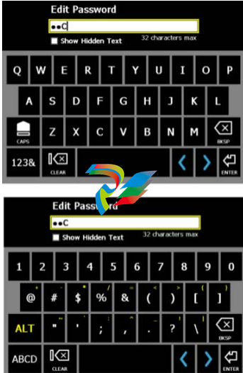
If the analyzer’s touchscreen is enabled/unlocked, the analyzer displays an onscreen
keyboard when you need to enter alphanumeric or special characters. See Section 2.12.1
for more information on locking or unlocking the touchscreen.
Note
Gestures are not supported when the analyzer displays the onscreen keyboard.
Tap the desired letter or character on the screen. The selected character is highlighted
yellow.
Figure 2-10: Examples of the onscreen keyboard
Menu navigation
The analyzer has a touchscreen and function keys for navigating and selecting menu
options. The menu options appear on the left and right sides of the screen and correspond
to the function keys on the analyzer. When you press a key or an option on the
touchscreen, a blue status LED flashes on the analyzer’s front panel.
To cancel or return to a previous screen, press the Back key. Press the Home key to return to
the Home screen.
2.13.1 ALT screens
Each screen displays up to 12 menu options, but additional options may be available on
alternate screens. ALT1 or ALT2 appears at the top of the screen and the function keys are
outlined in yellow. To switch screens, press the ALT key or the ALT label on the screen.
2.13.2 Entering text
If a menu option lets you enter text, an onscreen keyboard appears or the analyzer lists a
set of characters on the side of the screen. Tap the touchscreen or repeatedly press the key
until the desired character appears. Wait until the cursor moves and then enter the next
character. See Section 2.12.4 for more information about entering text using the keyboard.
Note
The onscreen keyboard appears only if the touchscreen is enabled/unlocked. By default, the
touchscreen is enabled/unlocked.
2.13.3 Display Help
Use the Help key to access information about a menu option or key.
Procedure
1.
Press the Help key .
2. Press a menu option.
The analyzer displays the Help text for that menu option.
3. Press Enter to close the Help text.
2.14 Settings
View and modify the default global settings from the Home ALT1 or ALT2 screens.
-
 CTI 2500-ADP2-DISC Discrete Wiring Adapter for Series 500
 -
 CTI 2500-ADP1 Analog Wiring Adapter for Series 500
 -
 CTI 2500C-RADP-RS485 Remote Base Controller Adapter for Series 500
 -
 CTI 2500C-RADP-RBC Profibus RBC Adapter for Series 500
 -
 CTI 2500C-PADP-120V 120VAC 50W Power Supply for Series 500
 -
 CTI 2500-RADP RBC Adapter for Series 500
 -
 CTI 2500-R4500 520/530/DBC Adapter for Series 500 - MATURE
 -
 CTI 2500-PADP Power Supply Adapter for Series 500
 -
 CTI 2500-IADP I/O Adapter for Series 500
 -
 CTI 2500-VP15A-N4-W7 15" Flat-Panel PC with Windows® 7 Embedded
 -
 CTI 2500S-27-1750 Slice I/O, Ethernet, RS232/485. 900MHz, 2DIO / 4UAI / 2AI
 -
 CTI 2500S-26-1750 Slice I/O, Ethernet, RS232/485. 900MHz, 8DIO / 2UAI
 -
 CTI 2500S-23-1750 Slice I/O, Ethernet, RS232/485. 900MHz, 4DI / 4DO / 2UAI / 2AO
 -
 CTI 2500S-27-1550 Slice I/O, RS232/485. 2DIO / 4UAI / 2AI
 -
 CTI 2500S-26-1550 Slice I/O, RS232/485. 8DIO / 2UAI
 -
 CTI 2500S-23-1550 Slice I/O, RS232/485. 4DI / 4DO / 2UAI / 2AO
 -
 CTI 2500S-27-1050 Slice I/O, Ethernet, 2DIO / 4UAI / 2AI
 -
 CTI 2500S-26-1050 Slice I/O, Ethernet, 8DIO / 2UAI
 -
 CTI 2500S-23-1050 Slice I/O, Ethernet, 4DI / 4DO / 2UAI / 2AO
 -
 CTI 2500C-32F-CJC 32-Pin Field Wiring Connector with Cold Junction Compensation
 -
 CTI 2500C-32F 32-Pin Field Wiring Connector
 -
 CTI 2500C-8-TC Eight Thermocouple Inputs
 -
 CTI 2500C-8-RTD Eight RTD Inputs
 -
 CTI 2500C-8-RL-FC 8 Form-C Relay Outputs
 -
 CTI 2500C-8-IDO-24V 8 Isolated 24VDC Outputs
 -
 CTI 2500C-8-IDO-120V 8 Isolated 120VAC Outputs
 -
 CTI 2500C-16-DO-24V Sixteen 24VDC Digital Outputs
 -
 CTI 2500C-16-DO-120V Sixteen 120VAC Digital Outputs
 -
.png) CTI 500C-16-IDI-24V Sixteen Isolated 24V AC/DC Digital Inputs
CTI 500C-16-IDI-24V Sixteen Isolated 24V AC/DC Digital Inputs -
 CTI 2500C-16-IDI-120V Sixteen Isolated 120V AC/DC Digital Inputs
 -
 CTI 2500C-16-DIDO-SIM Sixteen Digital Input and Output SImulator
 -
 CTI 2500C-16-DI-24V Sixteen 24V AC/DC Digital Inputs
 -
 CTI 2500C-16-DI-120V Sixteen 120V AC/DC Digital Inputs
 -
 CTI 2500C-RBC-RS485 RS485 Remote Base Controller
 -
 CTI 2500C-RBC-PRF Profibus Remote Base Controller
 -
 CTI 2500C-PS-24V-35 35-Watt DC Power Supply
 -
 CTI 2500C-PS-120V-35 35-Watt AC Power Supply
 -
 CTI 2500C-R8 Eight-Slot Base
 -
 CTI 2500C-R4 Four-Slot Base
 -
 CTI 2500C-R16 Sixteen-Slot Base
 -
 CTI 2500C-2572-B Fast Ethernet TCP/IP Adapter
 -
 CTI 2500C-J750 Compact Janus PAC with 3MB Project Memory
 -
 CTI 2500C-C300 CPU with 512K User Memory
 -
 CTI 2500C-C200 CPU with 256K User Memory
 -
 CTI 2500C-C100 CPU with 128K User Memory
 -
 CTI 2500C-8-AO 8 Analog Outputs
 -
 CTI 2500C-8-AI 8 Analog Inputs
 -
 CTI 2559-FCAL Precision Calibration Connector
 -
 CTI 2559-FPC 40-Position Screw-Terminal Connector
 -
 CTI 2500-RFC PLC to RF Modem Cable
 -
 CTI 2500-40F 40-Position Standard Screw-Terminal Connector
 -
 CTI 2505 Vibration Sensor Interface Module
 -
 CTI 2554-A 4-Channel Isolated High Speed Counter Module
 -
 CTI 2553-A 2-Channel Mag Meter Input Module
 -
 CTI 2502 2-Channel High Speed Counter Input Module
 -
 CTI 2559-TC 8-Channel Thermocouple Input Module
 -
 CTI 2556-A 16-Channel Isolated Thermocouple Input Module
 -
 CTI 2556 16-Channel Isolated Thermocouple Input Module
 -
 CTI 2551-A 8-Channel Isolated Thermocouple Input Module
 -
 CTI 2559-RTD 8-Channel RTD Input Module
 -
 CTI 2557-A 16-Channel RTD Input Module
 -
 CTI 2557 16-Channel RTD Input Module
 -
 CTI 2552-A 8-Channel Isolated RTD Input Module
 -
 CTI 2534 8-Point Form-C Relay Output Module
 -
 CTI 2532 16-Point Form-A Relay Output Module
 -
 CTI 2531 32-Point Form-A Relay Output Module
 -
 CTI 2530 8-Point Form-C Relay Output Module
 -
 CTI 2562 8-Channel Analog Output Module
 -
 CTI 2560-A 8-Channel Isolated Analog Output Module
 -
 CTI 2501 8in/4out Analog Module
 -
 CTI 2558 8-Channel Analog Input Module
 -
 CTI 2555-A 16-Channel Analog Input Module
 -
 CTI 2550-A 8-Channel Isolated Analog Input Module
 -
 CTI 2599 8/16/32-Point AC Output Module
 -
 CTI 2598-8 8-Point AC Output Module
 -
 CTI 2598 8/16-Point AC Output Module
 -
 CTI 2597 8/16/32-Point DC Output Module
 -
 CTI 2596-8 8-Point DC Output Module
 -
 CTI 2596 8/16-Point DC Output Module
 -
 CTI 2595 16-Point TTL/Word Output Module
 -
 CTI 2591-EF 16-Point Isolated 11-146 VDC Output with Front Panel Accessible Fuses
 -
 CTI 2591-A 16-Point Isolated 11-146 VDC Output Module
 -
 CTI 2590-EF 16-Point Isolated 20-132 VAC Output with Front Panel Accessible Fuses
 -
 CTI 2590-A 16-Point Isolated Discrete 20-132 VAC Output Module
 -
 CTI 2589-B 8/16/32-Point Universal Discrete Input Module
 -
 CTI 2589-A 8/16/32-Point Universal Discrete Input Module
 -
 CTI 2588-8 8-Point Universal Discrete Input Module
 -
 CTI 2585 16-Point TTL/Word Input Module
 -
 CTI 2582 16-Point Isolated 125 VDC Input Module
 -
 CTI 2581 16-Point Isolated 12-56 VDC Input Module
 -
 CTI 2580 16-Point Isolated 95-132 VAC Input Module
 -
 CTI 2500-TAP RS485 Network Tap
 -
 CTI 2500-RIO-B RS485 Remote Base Controller
 -
 CTI 2500-RIO-A RS485 Remote Base Controller
 -
 CTI 2500-RBC Profibus Remote Base Controller
 -
 CTI 2515-A 100-Watt AC/DC Power Supply with Redundancy Support
 -
 CTI 2515 100-Watt AC Power Supply (MATURE - replaced by 2515-A)
 -
 CTI 2513-A 75-Watt DC Power Supply with Redundancy Support
 -
 CTI 2513 75-Watt 24VDC Power Supply
 -
 CTI 2512-A 75-Watt AC/DC Power Supply with Redundancy Support
 -
 CTI 2512 75-Watt AC/DC Power Supply
 -
 CTI 2510 125 VDC Power Supply
 -
 CTI 2500-SSB Single Slot Blank Front Panel
 -
 CTI 2500-R11-A Eleven-Slot Redundant Base
 -
 CTI 2500P-R16 Sixteen-Slot Base with High-Speed Channel
 -
 CTI 2500P-R8 Eight-Slot Base with High-Speed Channel
 -
 CTI 2500P-R4 Four-Slot Base with High-Speed Channel
 -
 CTI 2541 Redundant Processor Manager Module
 -
 CTI 2577 Profibus DP Slave Adapter
 -
 CTI 2573-MOD Serial Interface Adapter with MODBUS
 -
 CTI 2572-AF Fast Ethernet TCP/IP Adapter with Optical Fiber Connection
 -
 CTI 2572-A Fast Ethernet TCP/IP Adapter
 -
 CTI 2572 Ethernet TCP/IP Adapter
 -
 CTI 2572-B Fast Ethernet TCP/IP Adapter
 -
 CTI 2576 DeviceNet™ Scanner Module (MATURE)
 -
 CTI 2500P-ECC1 Ethernet Communications Coprocessor
 -
 CTI 2500P-JACP Janus Application Coprocessor
 -
 CTI 2500P-ACP1 Application Coprocessor (MATURE - replaced by 2500P-JACP)
 -
 CTI 2500P-J450 Janus PAC with 2MB Project Memory
 -
 CTI 2500-C400 CPU with 3072K User Memory
 -
 CTI 2500-C300 CPU with 512K User Memory
 -
 CTI 2500-C200 CPU with 256K User Memory
 -
 CTI 2500-C100 CPU with 128K User Memory
 -
 CTI 2500P-J750 Janus PAC with 3MB Project Memory
 -
 Shinkawa WHF3006M Displacement Converter
 -
Shinkawa JBP-220 (P-24-94A / P-24-94B) Circuit Board Module
-
 SHINKAWA WKN-142K5 2-WIRE VIBRATION TRANSDUCER
 -
Shinkawa FRP-321 (P-26-54A / P-26-54B) Circuit Board Module


