
EMERSONAMS 2140 Machinery Health™ Analyzer
supply cord into an outlet and to the analyzer to activate the battery pack.
Procedure
1. Connect the provided power supply cord into an outlet and to the analyzer.
Note
Refer to precautions for the battery pack and power adapter.
The Battery LED is amber to indicate the battery pack is charging. The analyzer is
activated.
2. Press and hold the power key to turn the analyzer on.
The Home screen appears when you turn on the analyzer. The time and date are set
to a default value.
3. To set the time and date, press Home > ALT > F3 Set Time.
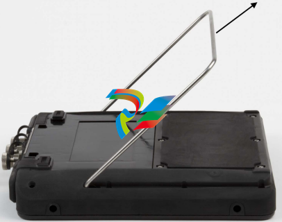
Use the stand
1. To put the stand in the upright position, grab the stand and pull up until the stand
locks.
2. To release the stand, place the analyzer face down, grab the base of the stand, and
gently pull.
The lock releases, and you can push the stand toward the analyzer.
Attach the shoulder strap
1. Press and hold the button on the strap connector, and insert it into the connectors
on the sides of the analyzer or the AMS 2140 Four-Channel Input Adapter, if
attached.
2. To release the strap, press and hold the button on the connector and then pull.
Battery pack
A rechargeable Lithium-Ion battery pack powers the analyzer. A typical charge should last
for more than 8 hours of continuous use. The analyzer displays a low-battery warning
when the remaining charge reaches a set level; the default is 15 percent. If the battery
pack fully discharges, you do not lose any data or settings.
The battery pack is shipped in storage mode to protect the battery charge. Refer to
Section 2.4 to activate the battery pack.
You do not need to discharge or calibrate the battery pack. The hardware optimizes
battery pack performance. Contact technical support if you experience any problems or
for instructions on how to store or replace the battery pack.
WARNING!
Use only Emerson battery packs with the AMS 2140. The analyzer will not function if a nonEmerson battery pack is used. Lithium-Ion batteries have very specific charging requirements.
Emerson power supplies and chargers are designed to work with the Emerson Lithium-Ion
battery pack. Using battery packs other than approved Emerson battery packs could not only
void the warranty, but could also be hazardous.
2.7.1 Access the battery pack
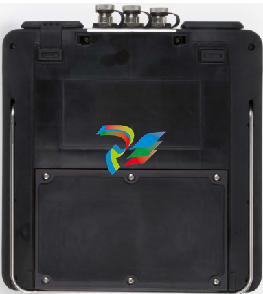
The battery pack is located on the back of the analyzer. To access the battery, remove the
six screws that attach it to the analyzer
Figure 2-4: Six battery pack screws
WARNING!
Remove the battery pack only in a non-hazardous area.
2.7.2 Battery pack and power supply precautions
Understand and follow the precautions below before using the battery pack and power
supply.
• Do not use Emerson’s battery packs, power supplies, and chargers with any product
other than their corresponding Emerson product.
• Use only Emerson’s power supplies and chargers approved for use with the AMS
2140 and Emerson’s battery packs. Using any power supplies and chargers other
than Emerson’s approved power supplies and battery packs could not only void the
warranty, but will also most likely damage the analyzer or the battery pack.
• Do not change or remove the battery pack in the AMS 2140 with the power supply
connected to the analyzer. The AMS 2140 or battery pack may be damaged.
• When charging the AMS 2140 with the battery pack or the battery pack by itself,
ensure the ambient temperature where charging is occurring is 50° F to 95° F (10° C
to 35° C).
• When operating the AMS 2140 with the battery pack, ensure the ambient
temperature where the analyzer is being used is -4° F to 122° F ( -20° C to 50° C).
WARNING!
• Use only Emerson’s battery packs with the AMS 2140. The analyzer will not function if a
non-Emerson battery pack is used. Lithium-Ion batteries have very specific charging
requirements. Emerson-supplied power supplies and chargers are designed to work
with Emerson’s Lithium-Ion battery pack. Using battery packs other than Emerson’s
approved battery packs could not only void the warranty, but could also be hazardous.
• Charge, remove, and replace the battery pack only in a non-hazardous area.
2.7.3 View the battery charge level
View the remaining charge level from the analyzer Home screen or from the LEDs on the
battery pack.
Procedure
Do one of the following:
• From the Home screen, view the remaining battery charge on the lower left side of the
screen.
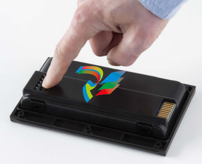
• Press the button on the inside of the battery pack. Each LED indicates approximately 20
percent remaining charge
Figure 2-5: Check the remaining charge from the battery pack
Note
If the battery pack has been placed in storage mode, the LEDs do not operate.
2.7.4 Charge the battery pack
The analyzer is fully operational during charging. As a best practice, charge the battery
pack frequently. Emerson recommends you charge the battery pack the night before you
intend to use it.
WARNING!
• Use only Emerson-supplied power supplies and chargers approved for use with the AMS
2140 and Emerson battery packs. Using any power supplies and chargers other than
approved Emerson power supplies and battery packs could not only void the warranty,
but will also most likely damage the analyzer or the battery pack.
• When charging the AMS 2140 with the battery pack or the battery pack by itself, ensure
-
 CTI 2500-ADP2-DISC Discrete Wiring Adapter for Series 500
 -
 CTI 2500-ADP1 Analog Wiring Adapter for Series 500
 -
 CTI 2500C-RADP-RS485 Remote Base Controller Adapter for Series 500
 -
 CTI 2500C-RADP-RBC Profibus RBC Adapter for Series 500
 -
 CTI 2500C-PADP-120V 120VAC 50W Power Supply for Series 500
 -
 CTI 2500-RADP RBC Adapter for Series 500
 -
 CTI 2500-R4500 520/530/DBC Adapter for Series 500 - MATURE
 -
 CTI 2500-PADP Power Supply Adapter for Series 500
 -
 CTI 2500-IADP I/O Adapter for Series 500
 -
 CTI 2500-VP15A-N4-W7 15" Flat-Panel PC with Windows® 7 Embedded
 -
 CTI 2500S-27-1750 Slice I/O, Ethernet, RS232/485. 900MHz, 2DIO / 4UAI / 2AI
 -
 CTI 2500S-26-1750 Slice I/O, Ethernet, RS232/485. 900MHz, 8DIO / 2UAI
 -
 CTI 2500S-23-1750 Slice I/O, Ethernet, RS232/485. 900MHz, 4DI / 4DO / 2UAI / 2AO
 -
 CTI 2500S-27-1550 Slice I/O, RS232/485. 2DIO / 4UAI / 2AI
 -
 CTI 2500S-26-1550 Slice I/O, RS232/485. 8DIO / 2UAI
 -
 CTI 2500S-23-1550 Slice I/O, RS232/485. 4DI / 4DO / 2UAI / 2AO
 -
 CTI 2500S-27-1050 Slice I/O, Ethernet, 2DIO / 4UAI / 2AI
 -
 CTI 2500S-26-1050 Slice I/O, Ethernet, 8DIO / 2UAI
 -
 CTI 2500S-23-1050 Slice I/O, Ethernet, 4DI / 4DO / 2UAI / 2AO
 -
 CTI 2500C-32F-CJC 32-Pin Field Wiring Connector with Cold Junction Compensation
 -
 CTI 2500C-32F 32-Pin Field Wiring Connector
 -
 CTI 2500C-8-TC Eight Thermocouple Inputs
 -
 CTI 2500C-8-RTD Eight RTD Inputs
 -
 CTI 2500C-8-RL-FC 8 Form-C Relay Outputs
 -
 CTI 2500C-8-IDO-24V 8 Isolated 24VDC Outputs
 -
 CTI 2500C-8-IDO-120V 8 Isolated 120VAC Outputs
 -
 CTI 2500C-16-DO-24V Sixteen 24VDC Digital Outputs
 -
 CTI 2500C-16-DO-120V Sixteen 120VAC Digital Outputs
 -
.png) CTI 500C-16-IDI-24V Sixteen Isolated 24V AC/DC Digital Inputs
CTI 500C-16-IDI-24V Sixteen Isolated 24V AC/DC Digital Inputs -
 CTI 2500C-16-IDI-120V Sixteen Isolated 120V AC/DC Digital Inputs
 -
 CTI 2500C-16-DIDO-SIM Sixteen Digital Input and Output SImulator
 -
 CTI 2500C-16-DI-24V Sixteen 24V AC/DC Digital Inputs
 -
 CTI 2500C-16-DI-120V Sixteen 120V AC/DC Digital Inputs
 -
 CTI 2500C-RBC-RS485 RS485 Remote Base Controller
 -
 CTI 2500C-RBC-PRF Profibus Remote Base Controller
 -
 CTI 2500C-PS-24V-35 35-Watt DC Power Supply
 -
 CTI 2500C-PS-120V-35 35-Watt AC Power Supply
 -
 CTI 2500C-R8 Eight-Slot Base
 -
 CTI 2500C-R4 Four-Slot Base
 -
 CTI 2500C-R16 Sixteen-Slot Base
 -
 CTI 2500C-2572-B Fast Ethernet TCP/IP Adapter
 -
 CTI 2500C-J750 Compact Janus PAC with 3MB Project Memory
 -
 CTI 2500C-C300 CPU with 512K User Memory
 -
 CTI 2500C-C200 CPU with 256K User Memory
 -
 CTI 2500C-C100 CPU with 128K User Memory
 -
 CTI 2500C-8-AO 8 Analog Outputs
 -
 CTI 2500C-8-AI 8 Analog Inputs
 -
 CTI 2559-FCAL Precision Calibration Connector
 -
 CTI 2559-FPC 40-Position Screw-Terminal Connector
 -
 CTI 2500-RFC PLC to RF Modem Cable
 -
 CTI 2500-40F 40-Position Standard Screw-Terminal Connector
 -
 CTI 2505 Vibration Sensor Interface Module
 -
 CTI 2554-A 4-Channel Isolated High Speed Counter Module
 -
 CTI 2553-A 2-Channel Mag Meter Input Module
 -
 CTI 2502 2-Channel High Speed Counter Input Module
 -
 CTI 2559-TC 8-Channel Thermocouple Input Module
 -
 CTI 2556-A 16-Channel Isolated Thermocouple Input Module
 -
 CTI 2556 16-Channel Isolated Thermocouple Input Module
 -
 CTI 2551-A 8-Channel Isolated Thermocouple Input Module
 -
 CTI 2559-RTD 8-Channel RTD Input Module
 -
 CTI 2557-A 16-Channel RTD Input Module
 -
 CTI 2557 16-Channel RTD Input Module
 -
 CTI 2552-A 8-Channel Isolated RTD Input Module
 -
 CTI 2534 8-Point Form-C Relay Output Module
 -
 CTI 2532 16-Point Form-A Relay Output Module
 -
 CTI 2531 32-Point Form-A Relay Output Module
 -
 CTI 2530 8-Point Form-C Relay Output Module
 -
 CTI 2562 8-Channel Analog Output Module
 -
 CTI 2560-A 8-Channel Isolated Analog Output Module
 -
 CTI 2501 8in/4out Analog Module
 -
 CTI 2558 8-Channel Analog Input Module
 -
 CTI 2555-A 16-Channel Analog Input Module
 -
 CTI 2550-A 8-Channel Isolated Analog Input Module
 -
 CTI 2599 8/16/32-Point AC Output Module
 -
 CTI 2598-8 8-Point AC Output Module
 -
 CTI 2598 8/16-Point AC Output Module
 -
 CTI 2597 8/16/32-Point DC Output Module
 -
 CTI 2596-8 8-Point DC Output Module
 -
 CTI 2596 8/16-Point DC Output Module
 -
 CTI 2595 16-Point TTL/Word Output Module
 -
 CTI 2591-EF 16-Point Isolated 11-146 VDC Output with Front Panel Accessible Fuses
 -
 CTI 2591-A 16-Point Isolated 11-146 VDC Output Module
 -
 CTI 2590-EF 16-Point Isolated 20-132 VAC Output with Front Panel Accessible Fuses
 -
 CTI 2590-A 16-Point Isolated Discrete 20-132 VAC Output Module
 -
 CTI 2589-B 8/16/32-Point Universal Discrete Input Module
 -
 CTI 2589-A 8/16/32-Point Universal Discrete Input Module
 -
 CTI 2588-8 8-Point Universal Discrete Input Module
 -
 CTI 2585 16-Point TTL/Word Input Module
 -
 CTI 2582 16-Point Isolated 125 VDC Input Module
 -
 CTI 2581 16-Point Isolated 12-56 VDC Input Module
 -
 CTI 2580 16-Point Isolated 95-132 VAC Input Module
 -
 CTI 2500-TAP RS485 Network Tap
 -
 CTI 2500-RIO-B RS485 Remote Base Controller
 -
 CTI 2500-RIO-A RS485 Remote Base Controller
 -
 CTI 2500-RBC Profibus Remote Base Controller
 -
 CTI 2515-A 100-Watt AC/DC Power Supply with Redundancy Support
 -
 CTI 2515 100-Watt AC Power Supply (MATURE - replaced by 2515-A)
 -
 CTI 2513-A 75-Watt DC Power Supply with Redundancy Support
 -
 CTI 2513 75-Watt 24VDC Power Supply
 -
 CTI 2512-A 75-Watt AC/DC Power Supply with Redundancy Support
 -
 CTI 2512 75-Watt AC/DC Power Supply
 -
 CTI 2510 125 VDC Power Supply
 -
 CTI 2500-SSB Single Slot Blank Front Panel
 -
 CTI 2500-R11-A Eleven-Slot Redundant Base
 -
 CTI 2500P-R16 Sixteen-Slot Base with High-Speed Channel
 -
 CTI 2500P-R8 Eight-Slot Base with High-Speed Channel
 -
 CTI 2500P-R4 Four-Slot Base with High-Speed Channel
 -
 CTI 2541 Redundant Processor Manager Module
 -
 CTI 2577 Profibus DP Slave Adapter
 -
 CTI 2573-MOD Serial Interface Adapter with MODBUS
 -
 CTI 2572-AF Fast Ethernet TCP/IP Adapter with Optical Fiber Connection
 -
 CTI 2572-A Fast Ethernet TCP/IP Adapter
 -
 CTI 2572 Ethernet TCP/IP Adapter
 -
 CTI 2572-B Fast Ethernet TCP/IP Adapter
 -
 CTI 2576 DeviceNet™ Scanner Module (MATURE)
 -
 CTI 2500P-ECC1 Ethernet Communications Coprocessor
 -
 CTI 2500P-JACP Janus Application Coprocessor
 -
 CTI 2500P-ACP1 Application Coprocessor (MATURE - replaced by 2500P-JACP)
 -
 CTI 2500P-J450 Janus PAC with 2MB Project Memory
 -
 CTI 2500-C400 CPU with 3072K User Memory
 -
 CTI 2500-C300 CPU with 512K User Memory
 -
 CTI 2500-C200 CPU with 256K User Memory
 -
 CTI 2500-C100 CPU with 128K User Memory
 -
 CTI 2500P-J750 Janus PAC with 3MB Project Memory
 -
 Shinkawa WHF3006M Displacement Converter
 -
Shinkawa JBP-220 (P-24-94A / P-24-94B) Circuit Board Module
-
 SHINKAWA WKN-142K5 2-WIRE VIBRATION TRANSDUCER
 -
Shinkawa FRP-321 (P-26-54A / P-26-54B) Circuit Board Module


