
EMERSONAMS 2140 Machinery Health™ Analyzer
conditions. If the ambient temperature exceeds normal and safe operating limits of 50° F
to 95° F (10° C to 35° C), charging stops. In most situations, charging automatically
resumes when the ambient temperature is within normal and safe operating limits.
• Use the external AMS 2140 Battery Charger only in a non-hazardous area.
This device complies with Part 15 of the FCC Rules. Operation is subject to the following
two conditions: (1) this device may not cause harmful interference, and (2) this device
must accept any interference received, including interference that may cause undesired
operation.
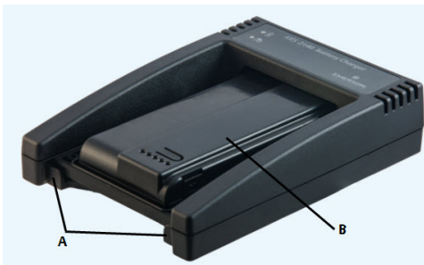
LEDs
Figure 2-7: LEDs on the front of the charger

A. Battery LED—Display a green light if the battery pack is fully charged, or an amber LED if the battery
pack is charging.
B. AC Power—Display a green light if the charger is being powered.
Charge the battery pack using the external AMS 2140
Battery Charger
You can charge your battery pack separately from the analyzer. You can use the charger
indoors, or you can use the automobile power supply cord to charge your analyzer in your
car. You can charge one battery pack at a time. A full recharge may take 3 hours.
Note
If the battery pack is in storage mode, placing the battery pack on the charger will activate the
battery pack.
WARNING!
• Use only Emerson-supplied power supplies and chargers approved for use with the AMS
2140 and Emerson battery packs. Using any power supplies and chargers other than
approved Emerson power supplies and battery packs could not only void the warranty,
but will also most likely damage the analyzer or the battery pack.
• Ensure the air vents on the external AMS 2140 Battery Charger are clear and uncovered.
• When charging the AMS 2140 with the battery pack or the battery pack by itself, ensure
the ambient temperature where charging is occurring is 50° F to 95° F (10° C to 35° C).
• Charge the battery pack only in a non-hazardous area.
Prerequisites
Remove the battery pack from the analyzer. See Section 2.7.6.
Procedure
1. With the metal contacts on the battery pack facing up, lift the battery pack over the
raised edges and then slide the battery pack into the charger.
Figure 2-8: Battery pack inserted into the external AMS 2140 Battery Charger
A. Raised edges
B. Battery pac
Insert the power supply cord into an outlet and into the connector on the back of
the external AMS 2140 Battery Charger.
Charging begins and the LED is amber. The battery pack is fully charged when the
battery LED on the external AMS 2140 Battery Charger changes from amber to
green. To check the progress, press the button on the battery pack next to the 5
LEDs. Each LED represents approximately 20 percent charge
To remove the battery pack, lift up the battery pack to clear the two raised edges,
and then slide out the battery pack
Turn the analyzer on or off
You can set the number of seconds to hold the power key to shut down the analyzer. See
Section 2.14.6.
Procedure
Press and hold the power key to turn the analyzer on or off.
The Home screen appears when you turn on the analyzer. If you were working in a
program before shutting down, that program appears.
2.9.1 Hard reboot
Do a hard reboot only if the analyzer is unresponsive.
Procedure
Press and hold the power key for approximately 10 seconds until the analyzer shuts
down.
2.9.2 Standby
Standby is similar to the standby mode on a computer. The analyzer is powered on, but the
backlight is off to conserve battery power. You can use standby mode to lock the
touchscreen and keys when you are carrying the analyzer. You can manually put the
analyzer in standby, or you can wait for the standby timer. See Section 2.14.2. The standby
timer also shuts off the keypad backlight.
Note
After 60 minutes in standby, the analyzer shuts down. You do not lose any data when this occurs.
Procedure
1.
To enter standby, quickly press (1 second) the power key , or wait for the
standby timer to expire.
The LCD backlight and keypad backlight turn off. The blue LED on the analyzer’s
front panel is lit.
2.
To leave standby, quickly press the power key .
Home screen
The Home screen appears when you turn on the analyzer by pressing the power key.
Figure 2-9: Home screen
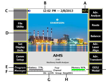
A. An alternate screen (ALT) includes additional options.
B. Current time and date.
C. Bluetooth device connection status (headphones connection icon shown).
D. Default splash screen.
E. Remaining battery pack charge.
F. Number of supported channels for the analyzer.
G. Serial number.
H. Group number for updating multiple analyzers at one site.
I. Available internal memory
Home screen programs and settings
The Home screen has two alternate screens that display programs and settings. ALT1 or
ALT2 appears at the top of the screen and the function keys are outlined in yellow. To
switch ALT screens, press the ALT key or the ALT text on the touchscreen.
ALT1 keys
Backlight
2.11.1 Set the LCD backlight
By default, the analyzer uses the Auto backlight mode to automatically adjust the backlight
intensity based on the light in your environment. You can disable the automatic
adjustments. You can set a timer to disable the backlight after a period of inactivity. See
Section 2.14.3.
Note
A higher backlight intensity decreases the battery pack life. For optimum battery pack life, set the
-
 Beckhoff Embedded-PC CX5010-1121
 -
 Beckhoff CB3050-0010 Mainboard Motherboard
 -
 Beckhoff PLC module CX1020-0000 Basic CPU module (service phase)
 -
 Beckhoff CP7812-1056-0010 15" Multitouch Display Control Panel
 -
 Beckhoff CX5120-0115 /2GB Controller Module
 -
 Beckhoff CP7201-1000-0000 Industrial Panel PC
 -
 Beckhoff Servo Motor AM8061-0JH1-0000
 -
 BECKHOFF CP6503-0001-0050 Built-in Panel PC
 -
 Beckhoff CP3919-0010 Display G190ETN01.2 19" PCT V04. Multi-touch Control Panel
 -
 Beckhoff CX5110-0112-9020/000368201 Embedded PC Intel Atom Processor
 -
 Beckhoff AX8206-0000 Dual-Axis Module
 -
Beckhoff Nail Operating Terminal CP7032-1031-0010
-
Beckhoff AM8042-0EH1-0000 Servomotor 4.10 Nm (M0), F4 (87 mm)
-
 Beckhoff EK9300 Beckhoff CPU Module
 -
Beckhoff CP3224-0020 Multitouch-Panel-PC
-
 Beckhoff CP2712-0000 12.1" 24VDC Touch Screen WMD0
 -
 BECKHOFF CX5240-0195 / 0000289234 Embedded PC 40 GB CFast Card
 -
 Beckhoff CP6932-1000-0000 Control Panel
 -
 BECKHOFF CX5120-0121 PLC Module
 -
 Beckhoff EL3218 | EtherCAT Terminal, 8-channel analog input
 -
 Beckhoff C6640-0050 | Control cabinet Industrial PC
 -
 Beckhoff Cx5130-0120/4GB Embedded-PC
 -
 BECKHOFF CX2030-0122 PLC PROCESSOR
 -
 BECKHOFF CX5020-0122 Controller Module
 -
 Beckhoff CP3915-0000 Multitouch Panel
 -
 BECKHOFF EL3014 | EtherCAT Terminal
 -
 BECKHOFF Industrial Computer c6920-1057-0030
 -
 Beckhoff CX5130-0141/4GB CX5130-0141 Embedded PC
 -
 Beckhoff C6240-1052-0040 4-086-06-3073 Industrial Computer
 -
 Beckhoff CX5140-0135 /4GB High-Performance Embedded Industrial PC
 -
 Beckhoff C6515-1001-0000 Industrial PC
 -
 Beckhoff AX5103-0000-0200 - Digital Compact Servo Drives
 -
 Beckhoff CX2030-0130-1003/4GB Basic CPU module
 -
 Beckhoff AX8620-0000 Power Supply Module
 -
 Beckhoff CX9020-0111 module with
 -
 Beckhoff EL7332 PLC Module
 -
 BECKHOFF CP7709-0001-0020 HMI
 -
 Beckhoff CX5120-0155/2GB Embedded PC
 -
 BECKHOFF CP7037-1037-0010 OPERATOR INTERFACE TOUCHSCREEN
 -
 Beckhoff EK9000 | ModbusTCP/UDP Bus Coupler
 -
 Beckhoff Touch Panel Screen CP6020 -0000-0000
 -
 Beckhoff CX2020-0121 Module FAST Shipping
 -
 Beckhoff CX2030-0125 Basic CPU Module
 -
 Beckhoff CP3918-0000 Multi-Touch 18.5" Control Panel
 -
 Automotion LC4A00010 DC BL Motor Control, ATS, Sub Assy, SCP, 115VAC,
 -
 500T-115VAC - VAS ENGINEERING - DORIC 500 SERIES DIGITAL TEMP INDICATOR
 -
 Honeywell X-DCS2000/EN Digital Integrated System Manager 50/60Hz 100-240V #4
 -
 Kollmorgen S60600 Servostar600 606-Fan 4 kVA, 6 A, 3 X 230 - 480 V
 -
 ABB XZ C828 A101 Didt Dioder Snubber 3BHE039453R0101
 -
 ABB 3BHB027232R0001 1-Phase Charging Transformer
 -
 ABB 3BHE006412R0101 Circuit Board UFC762AE101
 -
 ABB XVC770BE101 3BHE021083R0101 Circuit Board
 -
 ABB 3BHE021887R0101 (Model: UBCC717BE101 / UBC717BE101) is an advanced
 -
 ABB 3BHE032593R0001 Isolated Power Supply
 -
 ABB 3BSC610023R0001 POWER SUPPLY SD812
 -
 Beckhoff C6650-0060 | Control cabinet Industrial PC
 -
 Beckhoff CP2916-0000 Industrial HMI Display Panel
 -
 Beckhoff AM8053-0L2B-0000 Servomotor 15.4 Nm (M0), F5 (104 mm)
 -
 Beckhoff CP6202-0001-0020 Industrial Panel PC
 -
Beckhoff CX2020-0120 Plc Module
-
 Beckhoff CX1010-0111 BASIC CPU MODULE
 -
 Beckhoff C6017-0010 | Ultra-compact Industrial PC
 -
 BECKHOFF CX2040-0155 Plc Module
 -
 Beckhoff CX5120-0125 Embedded PC
 -
 BECKHOFF C6930-0040 INDUSTRIAL CONTROL COMPUTER
 -
 Beckhoff CP6907-0001-0000 Economy Built-in Control Panel
 -
 Beckhoff CP2912-0000 Multi-Touch Built-In Control Panel
 -
 Beckhoff C6015-0010 Ultra-Compact Industrial PC
 -
 Beckhoff CX5130 | Embedded PC with Intel Atom® E3827
 -
 Beckhoff C6030-0060 Ultra-Compact Industrial PC
 -
 OMRON 3G3XV-A2007 3G3XV-A2007-NEV2
 -
 Omron NJ1019000 NJ1 programable logic controller
 -
 OMRON C120-LK202-EV1/C120LK202EV1
 -
 OMRON C200H-AD003 PLC
 -
 OMRON C200H-CPU23-E COIL 24VDC PLC
 -
 Omron C200HG - C200H-ID212- C200H-OC226 C200HW-BC101 PLC Base Unit
 -
 OMRON C200H-OC222(Output Unit),C200H-PS211(Power Supply Unit),SP001 Module Rack
 -
 OMRON C200H-RT201 PROGRAMMABLE CONTROLLER
 -
 OMRON C200HS-CPU01-E SYSMAC PROGRAMMABLE CONTROLLER
 -
 OMRON C200H-SNT31 C200H Programmable Controllers
 -
 OMRON C200HW-MC402-E Motion control unit
 -
 OMRON C200PC-ISA02-DRM-E PLC ISA bus compatible board card
 -
 OMRON C500-CT012 PLC
 -
 OMRON C500-NC103-E PLC
 -
 OMRON C500-NC222-E PLC
 -
 OMRON C500-PRW05-V1 PLC
 -
 OMRON C500-PRW06 PROGRAMMABLE CONTROLLER
 -
 OMRON C500-PS223-E 3G2A5-PS223-E PLC SYSMAC PROGRAMMABLE CONTROLLER
 -
 OMRON C500-TU001 3G2A5-TU001 PLC PLC
 -
 OMRON C60H-C1DR-DE-V1 Programmable Controllers
 -
 OMRON C60H-C5DR-DE-V1 Programmable Controllers
 -
 OMRON C60H-C6DR-DE-V1 Programmable Controllers
 -
 OMRON CJ1G-CPU44H CPU module
 -
 OMRON CJ1G-CPU45H PLC
 -
 OMRON CJ1M-CPU13-ETN V4.0 PLC PLC
 -
 OMRON CJ1W-AD041-V1 Analog input uni
 -
 OMRON CJ1W-CORT21 PLC module
 -
 OMRON CJ1W-IDP01 Input unit
 -
 OMRON CJ1W-MCH71 - MECHATROLINK-II
 -
 OMRON CJ1W-MD261 Digital I/O
 -
 OMRON CJ1W-NC413 Position control unit
 -
 OMRON CJ1W-NCF71 Position Control Units
 -
 OMRON CJ1W-PTS51 Process Simulation I/O Module
 -
 OMRON CJ1W-PTS52 Process Simulation I/O Module
 -
 OMRON CJ1W-SCU21-V1 PLC
 -
 Omron CJ1W-SCU22 Serial Communication Unit
 -
 OMRON CJ1W-TC001 CJ Series Temperature Control Unit
 -
 Omron CK3W-AX1515N Motion Controller
 -
 Omron CP1E-N60DR-D Compact PLC CPU
 -
 OMRON CP1E-NA20DT1-D PLC PLC
 -
 OMRON CP1H-X40DT-D plc PLC
 -
 OMRON CPM2C-S110C-DRT Interface module
 -
 OMRON CQM1-AD041 PLC
 -
 SAACKE F‑GDSA‑1 / F‑GDSA‑2 Feuerungsautomaten
 -
 SAACKE F-GDSA 143303 Controller SHIPS UPS
 -
 ICS Triplex T8270 Trusted 24 Vdc FanAssembly
 -
 SCHNEIDER M522220000 SA SM_DO16R 16 DIGITAL OUTPUTS MODULE
 -
 LENZ EPL10200-W EPZ-10203 CANPT010W3E
 -
 OMRON CQM1H-ADB21 PLC
 -
OMRON CQM1H-CPU61 PLC
-
 OMRON CQM1H-MAB42 PLC
 -
 OMRON CQM1-TC102 CQM1-TC101 PLC
 -
 OMRON CS1G-CPU44-EV1 PLC
 -
 OMRON CS1G-CPU44H CPU
 -
OMRON CS1H-CPU63-EV1 PLC
-
 OMRON CS1H-CPU66-V1 PLC
 -
 OMRON CS1W-CLK13 PLC communication module
 -
OMRON CS1W-EIP21 PLC


