
EMERSONAMS 2140 Machinery Health™ Analyzer
the ambient temperature where charging is occurring is 50° F to 95° F (10° C to 35° C).
• Charge the battery pack only in a non-hazardous area.
Procedure
1. Remove the rubber plug on the top of the analyzer.
2. Insert the power supply connector into the analyzer. The analyzer can be powered
on or off.
Plug the AC connector on the power supply into a standard AC outlet, ranging from
100 VAC to 250 VAC, 50–60 Hz. A full recharge may take four hours.
The back of the analyzer may feel warm during charging. The power supply can
remain connected to the analyzer after charging completes. You cannot overcharge
the battery pack.
2.7.5 Battery LED indicates charging status
The Battery LED on the front of the analyzer shows the progress when charging the battery
pack. The LED is located to the right of the Power key.
Color Battery pack status
Amber Charging
Green Fully charged
2.7.6 Remove or change the battery pack
The analyzer gives you unlimited usage by changing the battery pack with a fully charged
spare battery pack. When you change the battery pack, the data saved in the analyzer is
not affected.
CAUTION!
Do not remove or change the battery pack with the power supply connected to the analyzer.
Damage may occur to the analyzer or the battery pack.
WARNING!
• Use only Emerson’s battery packs with the AMS 2140. The analyzer will not function if a
non-Emerson battery pack is used.
• Remove or change the battery pack only in a non-hazardous area.
Procedure
1. Turn off the analyzer and remove the power supply, if connected.
2. Set the analyzer face down on a level surface.
3. Lift up the stand.
4. On the back of the analyzer, remove the six screws that attach the battery pack to
the analyzer.
5. Carefully remove the battery pack from the battery compartment.
6. Insert the new battery pack and ensure it aligns with the contacts inside the battery
compartment on the analyzer.
7. Insert and tighten the six screws on the back panel.
Battery pack maintenance
To prevent any significant loss of the battery capacity when storing the analyzer with the
battery pack or storing the battery pack by itself for a prolonged period of time:
• Ensure the ambient temperature where the battery pack is located is -4° F to 95° F
( -20° C to 35° C). Due to the chemical composition of Lithium-Ion battery
technology, over time there will be some degradation that results in a reduced
charge capacity and performance. This degradation is unavoidable and irreversible.
Prolonged storage at temperatures outside this range, especially temperatures
above the high end, speeds up the degradation process.
• Disconnect the power supply from the AMS 2140 or the battery pack.
• When storing for 1–3 months, Emerson recommends removing the battery pack
from the AMS 2140.
• When storing the battery for longer than three months, contact Technical Support
to learn how to enter storage mode. Storage mode protects the battery during long
term storage. In storage mode, the analyzer and battery are non-functional. The
analyzer does not power on and the battery LEDs do not operate. Connect the
charger to the unit to reactivate the battery.
Note
If you do not enter storage mode, ensure the battery capacity is approximately 40 percent
and periodically recharge the battery pack (to approximately 40 percent charge capacity)
during storage to ensure the battery does not drain to low levels.
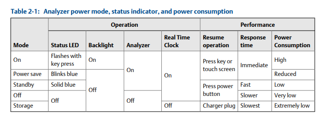
2.7.8 Conserve battery pack power
• Set timers to automatically put the analyzer in standby or turn off the backlight after
a set period of inactivity, such as not pressing any keys or not collecting data. You
can also put the analyzer into standby mode by quickly pressing the power key.
• Set the LCD backlight intensity to Medium. If you use the High setting, Emerson
recommends setting the backlight timer to 30 seconds.
These options are available on the General Analyzer Setup screen. Press Home > ALT > F2
General Setup.
The analyzer uses several power modes, or states, to conserve battery pack power.
Reference Table 2-1 when setting options on your analyzer that impact battery pack
power.
External AMS 2140 Battery Charger
The external AMS 2140 Battery Charger lets you charge the battery pack separately from
the analyzer. You can charge the battery pack indoors, or you can use the automobile
power supply cord to charge the battery in your car. You can charge one battery pack at a
time using the external AMS 2140 Battery Charger. A full recharge may take three hours.
To power the external AMS 2140 Battery Charger, insert the power supply cord into the
connector on the back of the charger.
Figure 2-6: Power supply connector and air vents
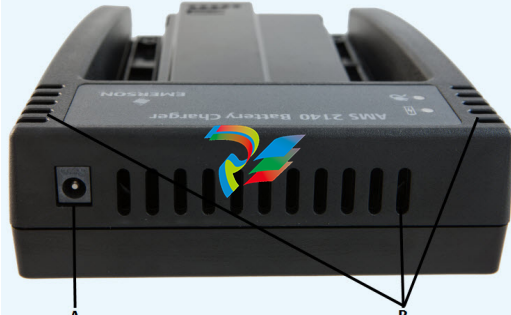
A. Power supply connector
B. Air vents
WARNING!
• To prevent overheating, ensure the air vents on the back and sides of the charger are
clear when charging a battery pack. To ensure proper airflow, allow several inches of
clearance around the charger and occasionally inspect the charger vents. Remove any
foreign material, such as dust, that may have settled around the vents.
• To prevent damage to the charger and battery pack, do not charge a battery pack in an
extremely hot or cold location, such as inside an automobile during summer or winter
-
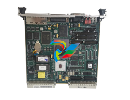
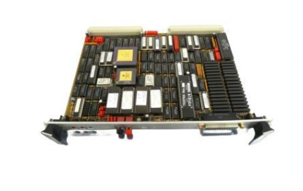
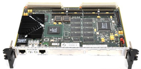
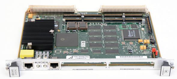
 MOTOROLA MVME172PA-652SE VME Embedded Controller
 -
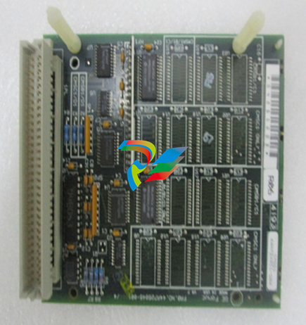
 MOTOROLA FLN4234A ACE3600 CPU3680 Processor Module
 -
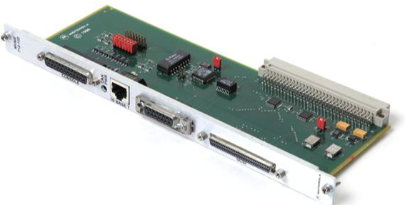
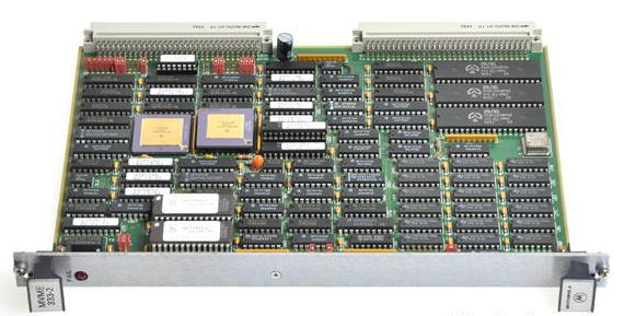 Motorola MVME333-2 Controller Communications Module Specs
 -
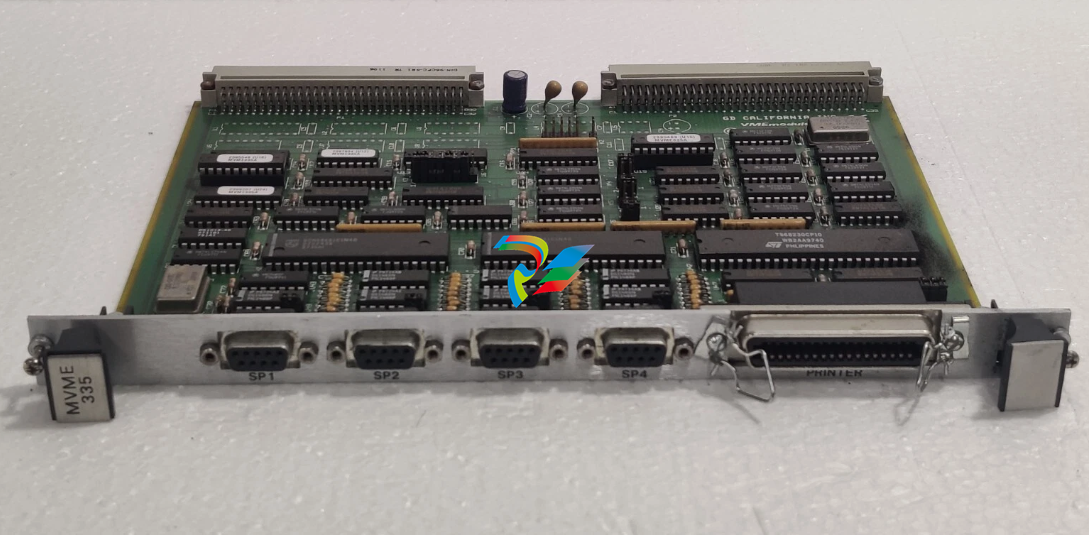 MOTOROLA MVME335 PCB California VME Module 0733500
 -
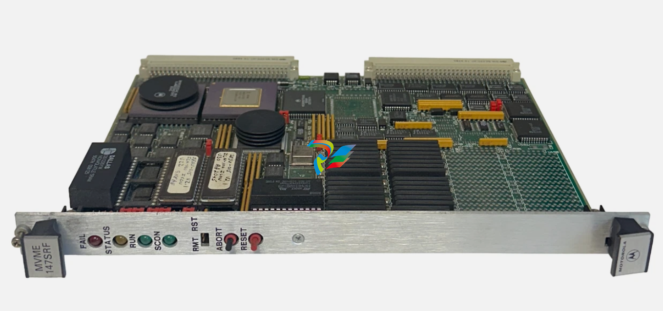 EMERSON MOTOROLA MVME-147SRF / MVME147SRF MPU VME MODULE
 -
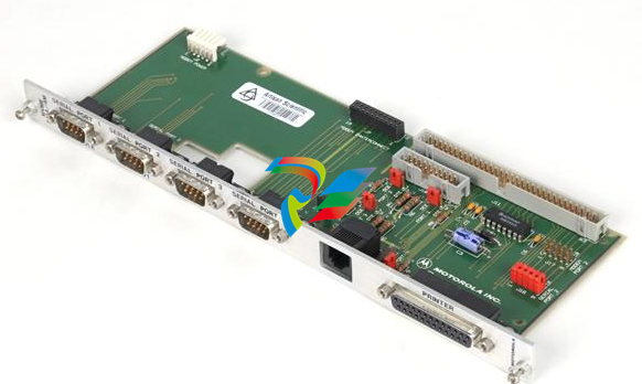
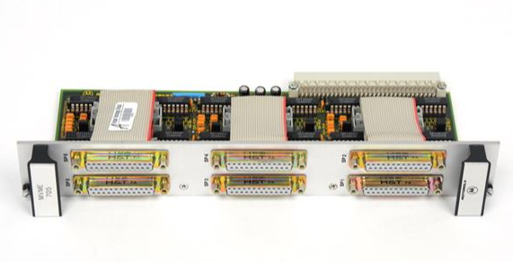 MOTOROLA MVME705A Serial Transition Module
 -
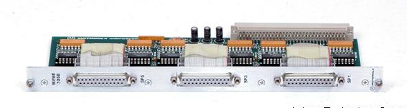 MOTOROLA MVME705B 6-Channel Serial Transition Module
 -
 MOTOROLA MVME712A MVME712AM I/O Transition Module
 -
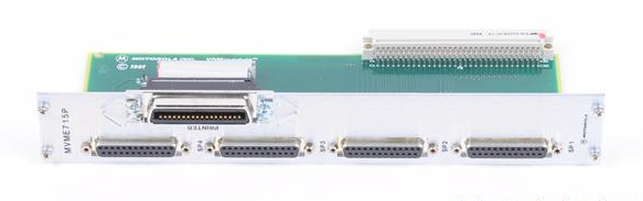 MOTOROLA MVME715P Rear Transition Module
 -
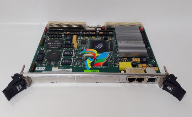
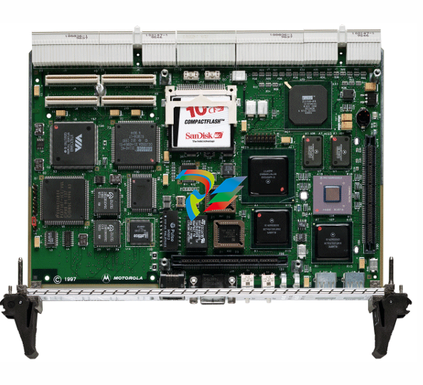
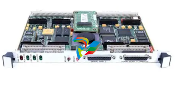 MOTOROLA MVME172 VME Embedded Controller
 -
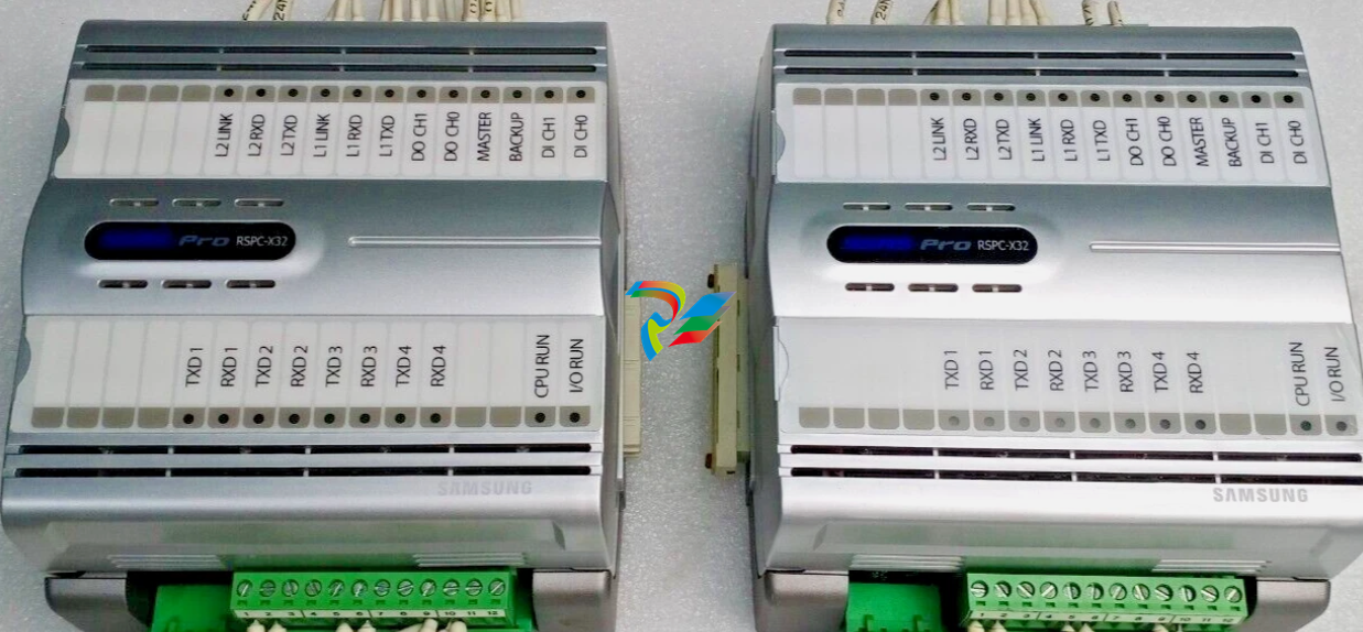 SAMSUNG SSAS-PRO RSPC-X32 ALARM AND MONITORING SYSTEM MODULE
 -
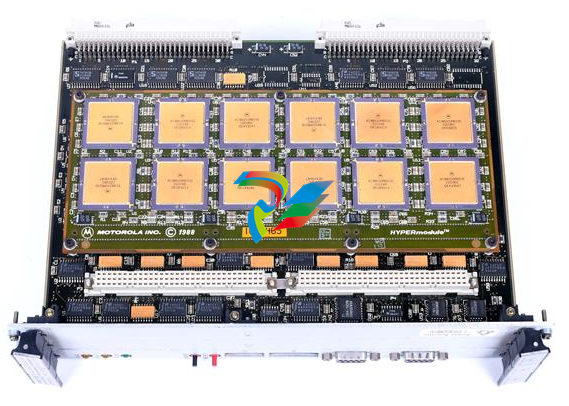
 MOTOROLA TMCP700 W33378F High-Performance Industrial Computing Module
 -
 MOTOROLA VME Single Board Computer MVME188A
 -
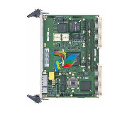
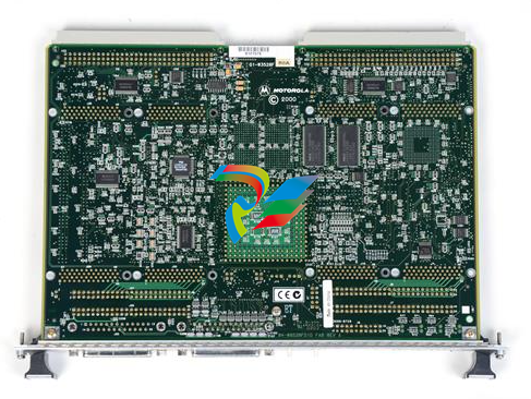 MOTOROLA MVME162PA-344 High-Performance Embedded VME Controller
 -
 MOTOROLA FAB 0340-1049 High-Efficiency Intelligent Embedded Module
 -
 MOTOROLA 30-W2960B01A High-Performance Industrial Interface Module
 -
 MOTOROLA MVME712M Transition Module.
 -
 MOTOROLA MVME5500 Series VME Single-Board
 -
 MOTOROLA MVME300 High-Reliability GPIB VMEbus Controller
 -
 MOTOROLA CPCI-6020TM High-Performance CompactPCI Transition Module
 -
 MOTOROLA MVME162-210 Embedded Controller
 -
 MOTOROLA MVME162-522A 01-W3960B/61C Embedded Controller
 -
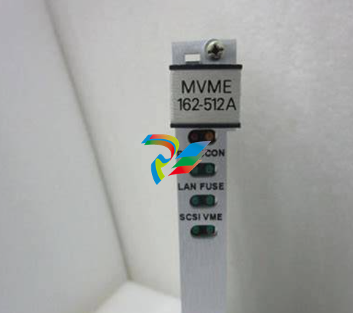 MOTOROLA MVME162-512A Embedded Controller
 -
 MOTOROLA MVME162-512 Embedded Controller
 -
 MOTOROLA MVME162-220 Embedded Controller
 -
 MOTOROLA MVME162-13 Embedded Controller
 -
 MOTOROLA MVME162-10 Embedded Controller
 -
 MOTOROLA MVME162-012 Embedded Controller
 -
 MOTOROLA MCP750 CompactPCI Host Slot Processor
 -
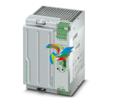 Phoenix 2320267 QUINT-UPS/ 24DC/ 24DC/10/3.4AH - Uninterruptible power supply
 -
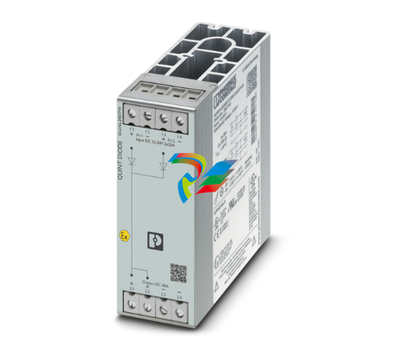
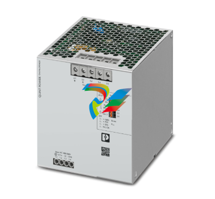 Phoenix QUINT4-PS/3AC/24DC/40 - Power supply 2904623
 -
 Phoenix 2904622 QUINT4-PS/3AC/24DC/20 - Power supply
 -
 Phoenix 2905012 QUINT-PS/96-110DC/24DC/10/CO - DC/DC converter, protective coating
 -
 Phoenix 2905011 QUINT-PS/60-72DC/24DC/10/CO - DC/DC converter, protective coating
 -
 Phoenix 2904600 QUINT4-PS/1AC/24DC/5 - Power supply
 -
 Phoenix 2904603 QUINT4-PS/1AC/24DC/40 - Power supply
 -
 Phoenix 2904601 QUINT4-PS/1AC/24DC/10 - Power supply
 -
 Phoenix 2904602 QUINT4-PS/1AC/24DC/20 - Power supply
 -
 Phoenix QUINT-PS/60-72DC/24DC/10 - DC/DC converter 2905009
 -
 Phoenix QUINT-PS/96-110DC/24DC/10 - DC/DC converter 2905010
 -
 Phoenix QUINT-PS/3AC/24DC/20/CO - Power supply, with protective coating 2320924
 -
 Phoenix QUINT-PS/1AC/12DC/20 - Power supply 2866721
 -
 Phoenix 2320908 QUINT-PS/1AC/24DC/ 5/CO - Power supply, with protective coating
 -
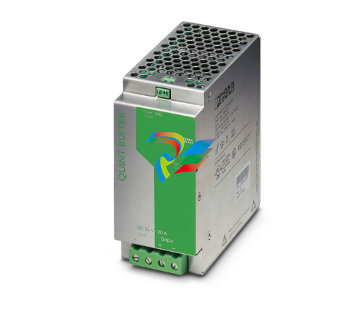 Phoenix 2866213 QUINT-BUFFER/24DC/20 - Buffer module
 -
 Phoenix 2866585 QUINT-DIODE/48DC/40 - Redundancy module, with protective coating
 -
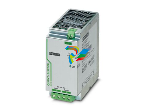 Phoenix 2320393 QUINT-BUFFER/24DC/24DC/40 - Buffer module
 -
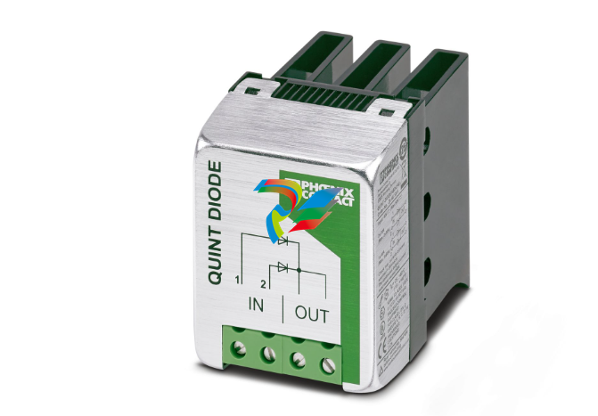
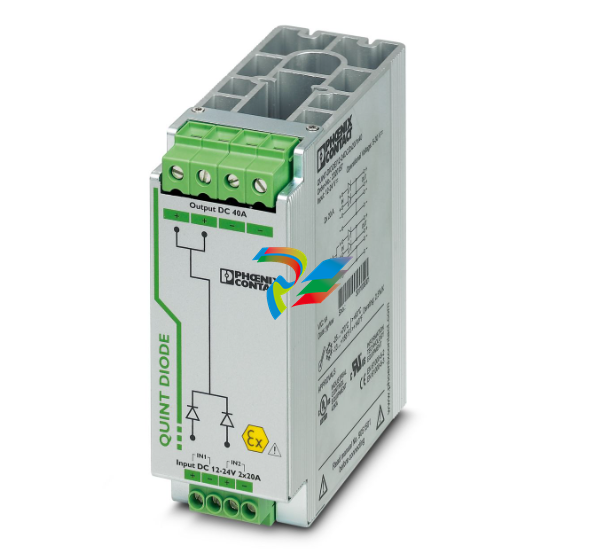 Phoenix 2320157 QUINT-DIODE/12-24DC/2X20/1X40 - Redundancy module
 -
 Phoenix 2907720 QUINT4-DIODE/48DC/2X20/1X40 - Redundancy module
 -
 Phoenix 2907719 QUINT4-DIODE/12-24DC/2X20/1X40 - Redundancy module
 -
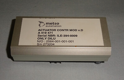 Metso A419471 High-Performance Analog Output Module
 -
 Applied Materials (AMAT) 0190-19092: High-Performance RF Match Controller Board
 -
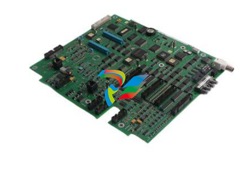 ABB UFC789AE101 3BHE014023R0101 High-Performance AC 800PEC Control Unit
 -
 GE MIFIIPA55E20HI00 Multilin MIF II Digital Feeder Protection Relay
 -
 GE DS3815PAHB1A1A Speedtronic Mark IV Processor & Interface Board
 -
 GE DS3800NB1A Speedtronic Mark IV Power Supply / Regulator Board
 -
 GE DS3800HIOC Speedtronic Mark IV High-Level Input/Output Board
 -
 GE DS3800NHVG Speedtronic Mark IV High-Voltage Gate Driver Board
 -
 ABB 1TGE120011R1010 MC M117 KIT 24VDC CMMB+PTC
 -
 Woodward 5448-897 Current Differential Protection Relay
 -
 GE IS220PAOCH1BE Mark VIe Analog I/O Module
 -
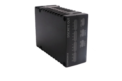 GE IS220PDOAH1B Mark VIe Discrete Output (PDOA) I/O Pack
 -
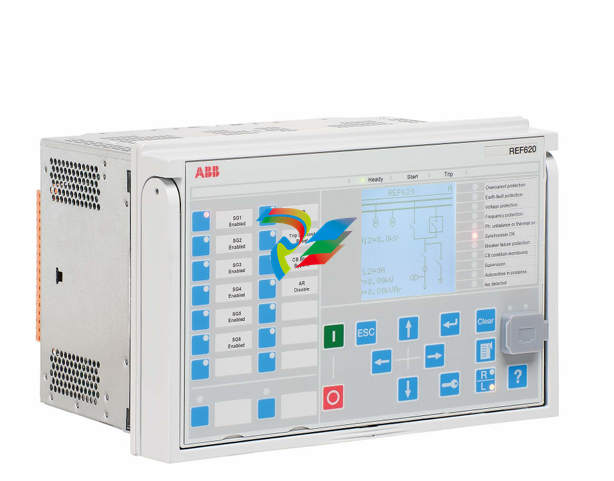 ABB Feeder Protection and Control REF620E_1G NBFNAAAAAABC6BBN11G
 -
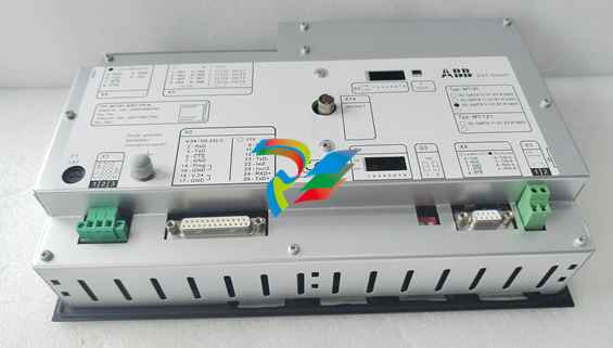 ABB MT-91-ARCFPA High-Precision Tension Control Interface Module
 -
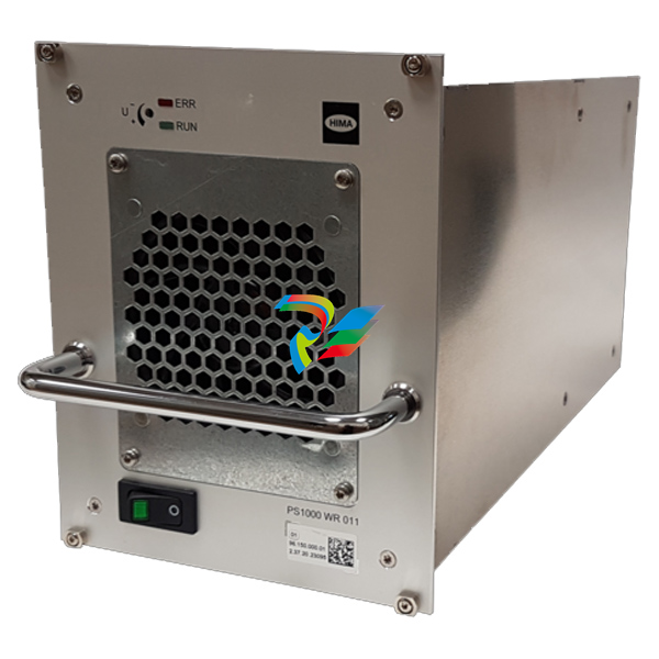 HIMA PS1000/230010 982200080 high-performance power supply module
 -
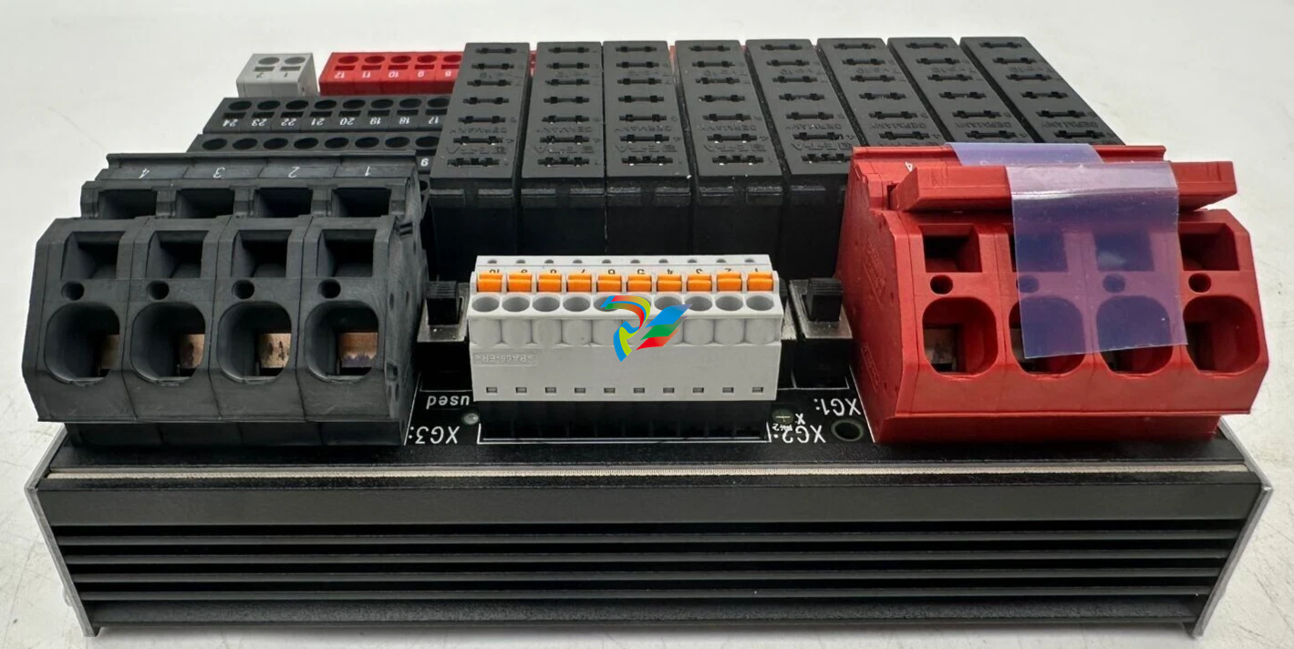 HIMA H7202 Distribution Fuse Board / Infeed Board
 -
 HIMA F60DIO24/1601 Safety-Related Controller
 -
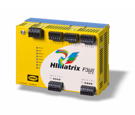
 HIMA F60DO801 Safety-Related Controller
 -
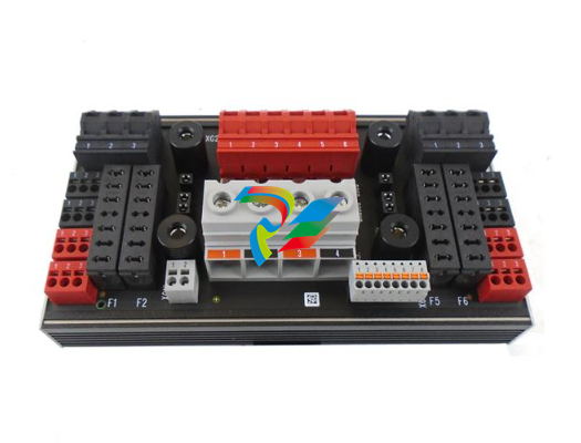 HIMA H7201 Line fuse board
 -
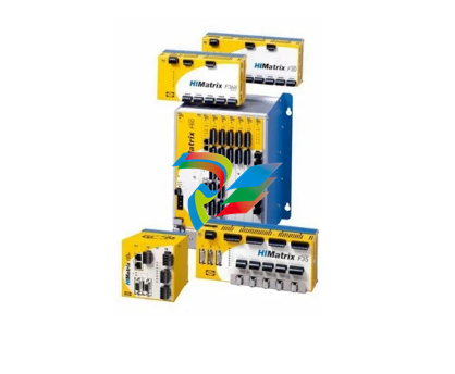
 HIMA HIMatrix ELOP II 892042336 Version V5.6 Build 1501.9810 IV1
 -
HIMA HIMatrix SILworX 504110 895400001
-
 HIMA HIMatrix SILworX 504111 895210001
 -
 HIMA OPC DA Server 892042400 Version 3.56.4
 -
 HIMA OPC Alarm & Event Server (892042420) Version 4.1.3
 -
 HIMA OPC Alarm & Event Server (892042420) Version 4.0.5
 -
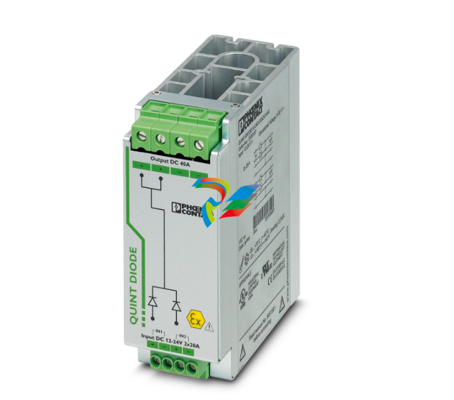 Phoenix QUINT-DIODE/12-24DC/2x20/1x40 2320157 Redundancy module
 -
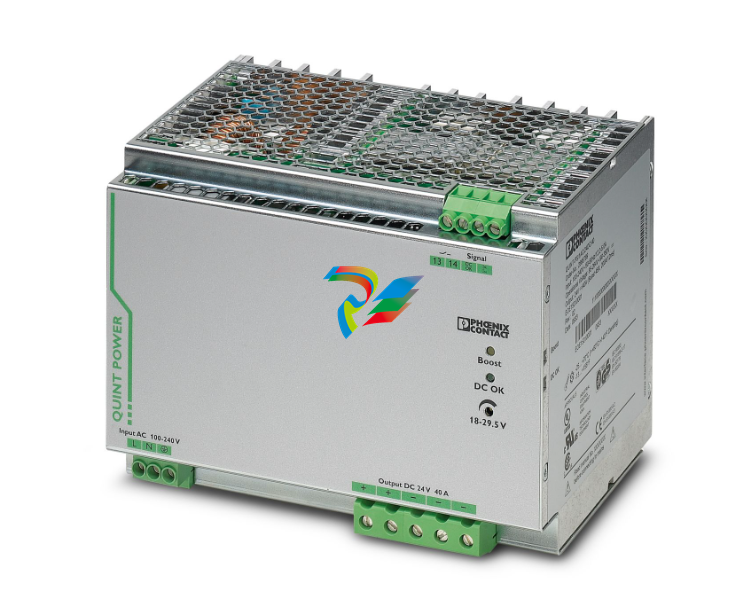 Phoenix QUINT-PS/1AC/24DC/40 2866789 Power supply
 -
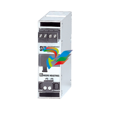 Moore SIY/PRG/4-20MA/10-42DC SIY PC Programmable Signal Isolator and Converter
 -
.png) Motorola 01-W3394F-03F Communication Interface Module
Motorola 01-W3394F-03F Communication Interface Module -
 Motorola AP-4 256 MByte 01-W3839F-07A Communication Module
 -
MOTOROLA MVME2432 01-W3394F-03C VME Processor Module
-
 MOTOROLA PCE I 01-W3839F-07A VME Processor Module
 -
.png) Motorola HPR431 / SYS431 / SYS443 / MFT543 Component Assembly
Motorola HPR431 / SYS431 / SYS443 / MFT543 Component Assembly -
Motorola AP-4 01-W3394F-03G Communication Interface Module
-
 Emerson 01-W3878F-02D DeltaV M-Series I/O Module
 -
 ICS Triplex Trusted T8232 Power Pack Module
 -
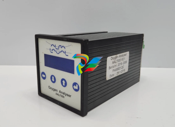 ALFA LAVAL AAL7000 OXYGEN ANALYSER V0.1
 -
Alstom MPM123 Measurement and Protection Module
-
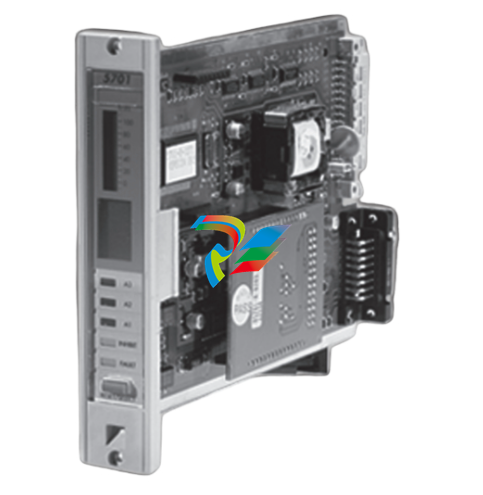 Honeywell 5701 CONTROL SYSTEM
 -
.png) KONGSBERG MRU-E-JB1 Host machine
KONGSBERG MRU-E-JB1 Host machine -
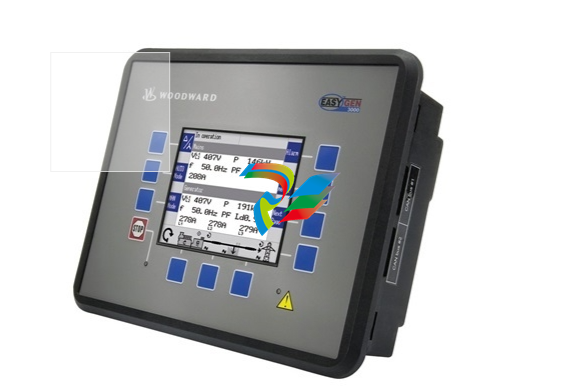 Woodward easYgen-3200-1/P1 8440-2049
 -
 Woodward easYPROTEC-1410-7 8441-1161 8441-1160
 -
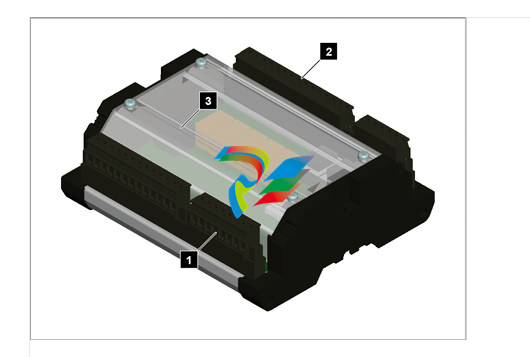
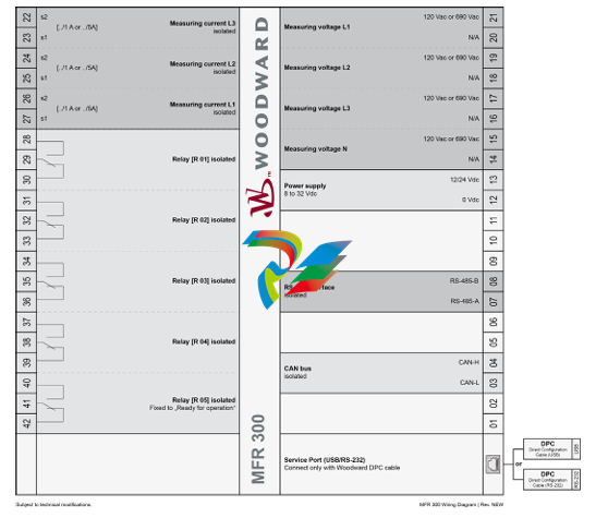
 Woodward MFR300-71M/K45 8444-1111 8444-1112
 -
 Woodward MFR300-75M 8444-1107 8444-1108 8444-1109
 -
 Woodward MFR300-71M/K42 8444-1104
 -
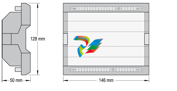
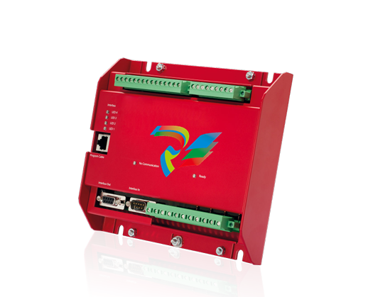
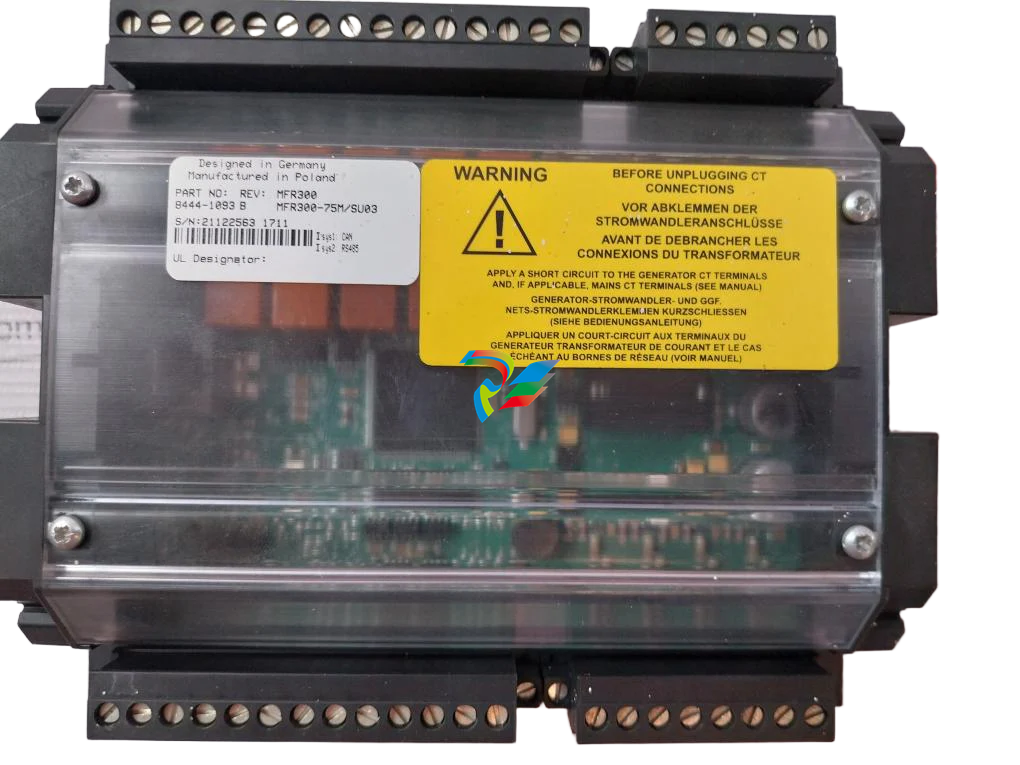 Woodward MFR300 75M/SU03, Transducer 8444-1093 8444-1094 8444-1095
 -
 Woodward MFR300-71M 8444-1091 8444-1092
 -
Woodward MFR300-15M 8444-1090 8444-1089
-
 Woodward MFR300-11M 8444-1071 8440-1089
 -
 Woodward MFR500-6M/WK0400 + DPC USB 8444-1070
 -
 Woodward MFR300-15M 8444-1064
 -
Woodward SPM-D2-1040B/NYB 8440-2189
-
Woodward SPM-D2-1010B/NYB 8440-2177
-
 Woodward SPM-D2-10B/PSY5-FU-D 8440-2170
 -
 Woodward SPM-D2-1040B/XN analog speed/voltage bias 8440-2190
 -
Woodward MFR300-71M 8444-1063
-
SPM-D2-1010B/X analog speed/voltage bias 8440-2168
-
 Woodward SPM-D2-1040B/X analog speed/voltage bias 8440-2171
 -
 Woodward SPM-D2-1010B/N wide range power supply 8440-2174
 -
Woodward SPM-D2-1040B/N wide range power supply 8440-2175
-
 Woodward SPM-D2-1010B /110VAC sensing 8440-2166
 -
Woodward SPM-D2-1040B /400VAC sensing 8440-2164
-
 Woodward DTSC-200A 8440-2297
 -
 Woodward DTSC-200-55B/K38 8440-2155
 -
Woodward DTSC-200-51B 8440-1867 8440-1868
-
 Woodward 8445-1049 8445-1048 Converter, 1x FO to CAN
 -
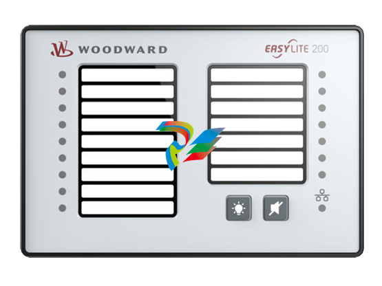 Woodward easYlite-200 8446-1007 LED Lamp Expansion Module
 -
 Woodward IKD-OUT-16 16 DO Expansion Card 8440-2306
 -
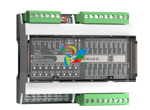 Woodward IKD-IN-16 16 DI Expansion Card 8440-2307
 -
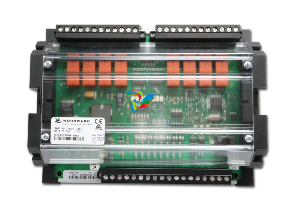 Woodward IKD1M 8 DI/8 DO Expansion Card 8440-2116
 -
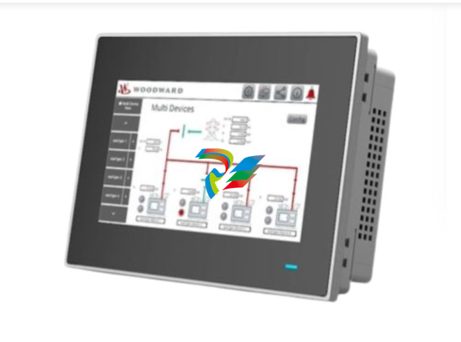 Woodward easYview-07-30 8446-1071
 -
 Woodward easYFLEX-3400XT-P2 (GAP) 8440-2217
 -
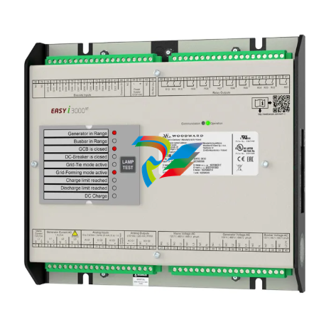
Woodward easY-I-3400XT-P1 8440-2293
-
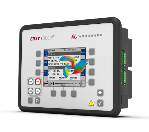
 Woodward easY-I-3500XT-P1 8440-2292
 -
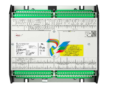 Woodward MSLC-2XT 8440-2298 Master Synchronizer and Load Control
 -
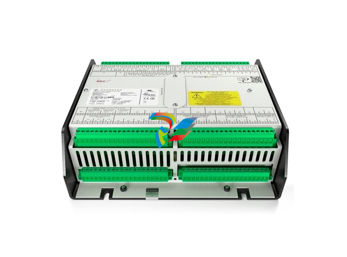 Woodward DSLC-2XT 8440-2299 Digital Synchronizer and Load Control
 -
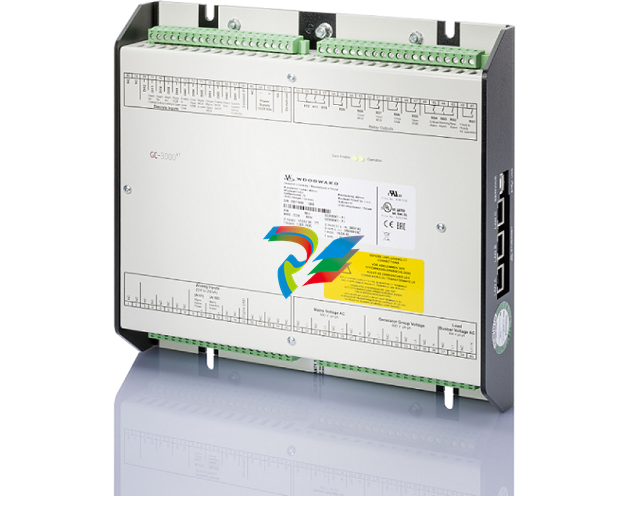 Woodward: GC-3400XT-P1 8440-2267 Group Controller
 -
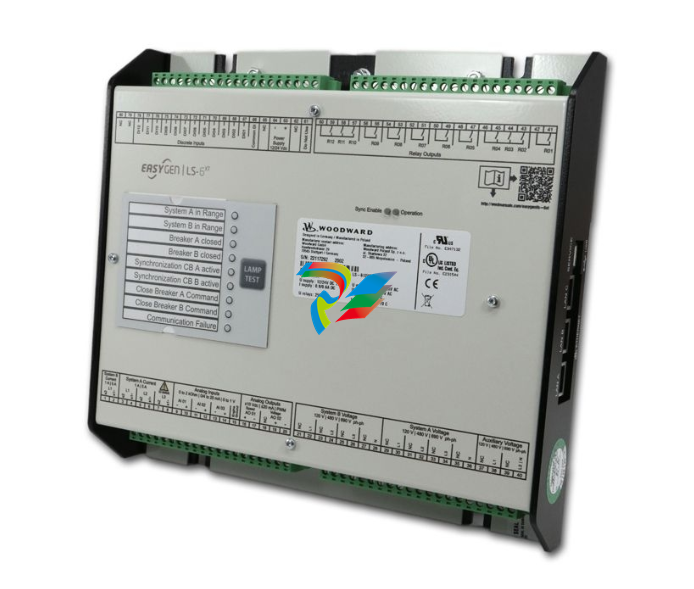 Woodward: LS-612XT-P2 8440-2317
 -
 Woodward: CONTROL-LS-612XT-P1,8440-2222 Cabinet back mounting


